SlideShare a Scribd company logo
CS60002
Distributed Systems
Praveen Varma
Supervisors: Praveen
www.carrertime.in
Text Book:
• “Advanced Concepts in Operating Systems” by
Mukesh Singhal and Niranjan G. Shivaratri
will cover about half the course, supplemented by
copies of papers
Xerox, notes, copies of papers etc. will cover
the rest.
What is a distributed system?
A very broad definition:
A set of autonomous processes communicating
among themselves to perform a task
Autonomous: able to act independently
Communication: shared memory or message
passing
“Concurrent system” : a better term probably
What is a distributed system?
A very broad definition:
A set of autonomous processes communicating
among themselves to perform a task
Autonomous: able to act independently
Communication: shared memory or message
passing
“Concurrent system” : a better term probably
A more restricted definition:
• A network of autonomous computers that
communicate by message passing to perform some
task
A practical “distributed system” will probably have both
– Computers that communicate by messages
– Processes/threads on a computer that communicate
by messages or shared memory
Advantages
• Resource Sharing
• Higher Performance
• Fault Tolerance
• Scalability
Why is it hard to design them?
The usual problem of concurrent systems:
– Arbitrary interleaving of actions makes the
system hard to verify
Plus
• No globally shared memory (therefore hard to
collect global state)
• No global clock
• Unpredictable communication delays
Models for Distributed Algorithms
– Topology : completely connected, ring, tree etc.
– Communication : shared memory/message passing
(reliable? Delay? FIFO/Causal? Broadcast/multicast?)
– Synchronous/asynchronous
– Failure models (fail stop, crash, omission,
Byzantine…)
An algorithm need to specify the model on which it is
supposed to work
Complexity Measures
• Message complexity : no. of messages
• Communication complexity/Bit Complexity : no.
of bits
• Time complexity : For synchronous systems, no.
of rounds. For asynchronous systems, different
definitions are there.
Some Fundamental Problems
• Ordering events in the absence of a global clock
• Capturing the global state
• Mutual exclusion
• Leader election
• Clock synchronization
• Termination detection
• Constructing spanning trees
• Agreement protocols
Ordering of Events and
Logical Clocks
Ordering of Events
Lamport’s Happened Before relationship:
For two events a and b, a → b if
 a and b are events in the same process and a
occurred before b
 a is a send event of a message m and b is the
corresponding receive event at the destination
process
 a → c and c → b for some event c
a → b implies a is a potential cause of b
Causal ordering : potential dependencies
“Happened Before” relationship causally orders
events
• If a → b, then a causally affects b
• If a → b and b → a, then a and b are
concurrent ( a || b)
Logical Clock
Each process i keeps a clock Ci.
• Each event a in i is timestamped C(a), the
value of Ci when a occured
• Ci is incremented by 1 for each event in i
• In addition, if a is a send of message m from
process i to j, then on receive of m,
Cj = max(Cj, C(a)+1)
Points to note:
• if a → b, then C(a) < C(b)
• → is an irreflexive partial order
• Total ordering possible by arbitrarily ordering
concurrent events by process numbers
Limitation of Lamport’s Clock
a → b implies C(a) < C(b)
BUT
C(a) < C(b) doesn’t imply a → b !!
So not a true clock !!
Solution: Vector Clocks
Ci is a vector of size n (no. of processes)
C(a) is similarly a vector of size n
Update rules:
• Ci[i]++ for every event at process i
• if a is send of message m from i to j with
vector timestamp tm, on receive of m:
Cj[k] = max(Cj[k], tm[k]) for all k
For events a and b with vector timestamps ta and tb,
• ta = tb iff for all i, ta[i] = tb[i]
• ta ≠ tb iff for some i, ta[i] ≠ tb[i]
• ta ≤ tb iff for all i, ta[i] ≤ tb[i]
• ta < tb iff (ta ≤ tb and ta ≠ tb)
• ta || tb iff (ta < tb and tb < ta)
• a → b iff ta < tb
• Events a and b are causally related iff ta < tb or tb
< ta, else they are concurrent
• Note that this is still not a total order
Causal ordering of messages:
application of vector clocks
• If send(m1)→ send(m2), then every recipient of
both message m1 and m2 must “deliver” m1 before
m2.
“deliver” – when the message is actually given to
the application for processing
Birman-Schiper-Stephenson Protocol
• To broadcast m from process i, increment Ci(i),
and timestamp m with VTm = Ci[i]
• When j ≠ i receives m, j delays delivery of m until
– Cj[i] = VTm[i] –1 and
– Cj[k] ≥ VTm[k] for all k ≠ i
– Delayed messaged are queued in j sorted by vector
time. Concurrent messages are sorted by receive
time.
• When m is delivered at j, Cj is updated according
to vector clock rule.
Problem of Vector Clock
• message size increases since each
message needs to be tagged with the
vector
• size can be reduced in some cases by
only sending values that have changed
Capturing Global State
Global State Collection
Applications:
– Checking “stable” properties, checkpoint &
recovery
Issues:
– Need to capture both node and channel
states
– system cannot be stopped
– no global clock
Some notations:
– LSi : local state of process i
– send(mij) : send event of message mij from
process i to process j
– rec(mij) : similar, receive instead of send
– time(x) : time at which state x was recorded
– time (send(m)) : time at which send(m)
occured
send(mij) є LSi iff
time(send(mij)) < time(LSi)
rec(mij) є LSj iff
time(rec(mij)) < time(LSj)
transit(LSi,LSj) = { mij | send(mij) є LSi and rec(mij) є
LSj}
inconsistent(LSi, LSj) = {mij | send(mij) є LSi and
Global state: collection of local states
GS = {LS1, LS2,…, LSn}
GS is consistent iff
for all i, j, 1 ≤ i, j ≤ n,
inconsistent(LSi, LSj) = Ф
GS is transitless iff
for all i, j, 1 ≤ i, j ≤ n,
transit(LSi, LSj) = Ф
Chandy-Lamport’s Algorithm
• Uses special marker messages.
• One process acts as initiator, starts the state
collection by following the marker sending rule
below.
• Marker sending rule for process P:
– P records its state; then for each outgoing
channel C from P on which a marker has not
been sent already, P sends a marker along C
before any further message is sent on C
• When Q receives a marker along a channel C:
– If Q has not recorded its state then Q records
the state of C as empty; Q then follows the
marker sending rule
– If Q has already recorded its state, it records
the state of C as the sequence of messages
received along C after Q’s state was recorded
and before Q received the marker along C
Points to Note:
• Markers sent on a channel distinguish
messages sent on the channel before the
sender recorded its states and the messages
sent after the sender recorded its state
• The state collected may not be any state that
actually happened in reality, rather a state that
“could have” happened
• Requires FIFO channels
• Network should be strongly connected (works
obviously for connected, undirected also)
• Message complexity O(|E|), where E = no. of
links
Lai and Young’s Algorithm
• Similar to Chandy-Lamport’s, but does not
require FIFO
• Boolean value X at each node, False indicates
state is not recorded yet, True indicates
recorded
• Value of X piggybacked with every application
message
• Value of X distinguishes pre-snapshot and post-
snapshot messages, similar to the Marker
Mutual Exclusion
Mutual Exclusion
• very well-understood in shared memory systems
• Requirements:
– at most one process in critical section (safety)
– if more than one requesting process,
someone enters (liveness)
– a requesting process enters within a finite
time (no starvation)
– requests are granted in order (fairness)
Classification of Distributed Mutual
Exclusion Algorithms
• Non-token based/Permission based
– Permission from all processes: e.g. Lamport,
Ricart-Agarwala, Raicourol-Carvalho etc.
– Permission from a subset: ex. Maekawa
• Token based
– ex. Suzuki-Kasami
Some Complexity Measures
• No. of messages/critical section entry
• Synchronization delay
• Response time
• Throughput
Lamport’s Algorithm
• Every node i has a request queue qi, keeps
requests sorted by logical timestamps (total
ordering enforced by including process id in the
timestamps)
To request critical section:
– send timestamped REQUEST (tsi, i) to all
other nodes
– put (tsi, i) in its own queue
On receiving a request (tsi, i):
– send timestamped REPLY to the requesting
node i
To enter critical section:
– i enters critical section if (tsi, i) is at the top if its own
queue, and i has received a message (any message)
with timestamp larger than (tsi, i) from ALL other
nodes.
To release critical section:
– i removes it request from its own queue and sends a
timestamped RELEASE message to all other nodes
– On receiving a RELEASE message from i, i’s request
is removed from the local request queue
Some points to note:
• Purpose of REPLY messages from node i to j is
to ensure that j knows of all requests of i prior to
sending the REPLY (and therefore, possibly any
request of i with timestamp lower than j’s
request)
• Requires FIFO channels.
• 3(n – 1 ) messages per critical section
invocation
• Synchronization delay = max. message
transmission time
• requests are granted in order of increasing
Ricart-Agarwala Algorithm
• Improvement over Lamport’s
• Main Idea:
– node j need not send a REPLY to node i if j
has a request with timestamp lower than the
request of i (since i cannot enter before j
anyway in this case)
• Does not require FIFO
• 2(n – 1) messages per critical section invocation
• Synchronization delay = max. message
transmission time
• requests granted in order of increasing
timestamps
To request critical section:
– send timestamped REQUEST message (tsi, i)
On receiving request (tsi, i) at j:
– send REPLY to i if j is neither requesting nor
executing critical section or if j is requesting and i’s
request timestamp is smaller than j’s request
timestamp. Otherwise, defer the request.
To enter critical section:
– i enters critical section on receiving REPLY from all
nodes
To release critical section:
– send REPLY to all deferred requests
Roucairol-Carvalho Algorithm
• Improvement over Ricart-Agarwala
• Main idea
– once i has received a REPLY from j, it does
not need to send a REQUEST to j again
unless it sends a REPLY to j (in response to a
REQUEST from j)
– no. of messages required varies between 0
and 2(n – 1) depending on request pattern
– worst case message complexity still the same
Maekawa’s Algorithm
• Permission obtained from only a subset of other
processes, called the Request Set (or Quorum)
• Separate Request Set Ri for each process i
• Requirements:
– for all i, j: Ri ∩ Rj ≠ Φ
– for all i: i Є Ri
– for all i: |Ri| = K, for some K
– any node i is contained in exactly D Request
Sets, for some D
• K = D = sqrt(N) for Maekawa’s
A simple version
To request critical section:
– i sends REQUEST message to all process in Ri
On receiving a REQUEST message:
– send a REPLY message if no REPLY message has
been sent since the last RELEASE message is
received. Update status to indicate that a REPLY has
been sent. Otherwise, queue up the REQUEST
To enter critical section:
– i enters critical section after receiving REPLY from all
nodes in Ri
To release critical section:
– send RELEASE message to all nodes in Ri
– On receiving a RELEASE message, send
REPLY to next node in queue and delete the
node from the queue. If queue is empty,
update status to indicate no REPLY message
has been sent.
• Message Complexity: 3*sqrt(N)
• Synchronization delay =
2 *(max message transmission time)
• Major problem: DEADLOCK possible
• Need three more types of messages (FAILED,
INQUIRE, YIELD) to handle deadlock. Message
complexity can be 5*sqrt(N)
• Building the request sets?
Token based Algorithms
• Single token circulates, enter CS when token is
present
• No FIFO required
• Mutual exclusion obvious
• Algorithms differ in how to find and get the token
• Uses sequence numbers rather than timestamps
to differentiate between old and current requests
Suzuki Kasami Algorithm
• Broadcast a request for the token
• Process with the token sends it to the requestor
if it does not need it
Issues:
– Current vs. outdated requests
– determining sites with pending requests
– deciding which site to give the token to
• The token:
– Queue (FIFO) Q of requesting processes
– LN[1..n] : sequence number of request that j executed
most recently
• The request message:
– REQUEST(i, k): request message from node i for its
kth
critical section execution
• Other data structures
– RNi[1..n] for each node i, where RNi[j] is the largest
sequence number received so far by i in a REQUEST
message from j.
To request critical section:
– If i does not have token, increment RNi[i] and send
REQUEST(i, RNi[i]) to all nodes
– if i has token already, enter critical section if the token
is idle (no pending requests), else follow rule to
release critical section
On receiving REQUEST(i, sn) fat j:
– set RNj[i] = max(RNj[i], sn)
– if j has the token and the token is idle, send it to i if
RNj[i] = LN[i] + 1. If token is not idle, follow rule to
release critical section
To enter critical section:
– enter CS if token is present
To release critical section:
– set LN[i] = RNi[i]
– For every node j which is not in Q (in token),
add node j to Q if RNi[ j ] = LN[ j ] + 1
– If Q is non empty after the above, delete first
node from Q and send the token to that node
Points to note:
– No. of messages: 0 if node holds the token
already, n otherwise
– Synchronization delay: 0 (node has the token)
or max. message delay (token is elsewhere)
– No starvation
Raymond’s Algorithm
• Forms a directed tree (logical) with the token-
holder as root
• Each node has variable “Holder” that points to its
parent on the path to the root. Root’s Holder
variable points to itself
• Each node i has a FIFO request queue Qi
• To request critical section:
– Send REQUEST to parent on the tree,
provided i does not hold the token currently
and Qi is empty. Then place request in Qi
• When a non-root node j receives a request from
i
– place request in Qj
– send REQUEST to parent if no previous
REQUEST sent
• When the root receives a REQUEST:
– send the token to the requesting node
– set Holder variable to point to that node
• When a node receives the token:
– delete first entry from the queue
– send token to that node
– set Holder variable to point to that node
– if queue is non-empty, send a REQUEST message to
the parent (node pointed at by Holder variable)
• To execute critical section:
– enter if token is received and own entry is at the top
of the queue; delete the entry from the queue
• To release critical section
– if queue is non-empty, delete first entry from the
queue, send token to that node and make Holder
variable point to that node
– If queue is still non-empty, send a REQUEST
message to the parent (node pointed at by Holder
variable)
Points to note:
• Avg. message complexity O(log n)
• Sync. delay (T log n)/2, where T = max.
message delay
Leader Election
Leader Election in Rings
• Models
– Synchronous or Asynchronous
– Anonymous (no unique id) or Non-anonymous
(unique ids)
– Uniform (no knowledge of ‘n’, the number of
processes) or non-uniform (knows ‘n’)
• Known Impossibility Result:
– There is no Synchronous, non-uniform leader
election protocol for anonymous rings
– Implications ??
Election in Asynchronous Rings
Lelann-Chang-Robert’s Algorithm
– send own id to node on left
– if an id received from right, forward id to left
node only if received id greater than own id,
else ignore
– if own id received, declares itself “leader”
• works on unidirectional rings
• message complexity = θ(n^2)
• Hirschberg-Sinclair Algorithm
– operates in phases, requires bidirectional ring
– In kth phase, send own id to 2^k processes on
both sides of yourself (directly send only to next
processes with id and k in it)
– if id received, forward if received id greater than
own id, else ignore
– last process in the chain sends a reply to
originator if its id less than received id
– replies are always forwarded
– A process goes to (k+1)th phase only if it receives
a reply from both sides in kth phase
– process receiving its own id – declare itself
“leader”
• Message Complexity: O(nlgn)
• Lots of other algorithms exist for rings
• Lower Bound Result:
– Any comparison-based leader election
algorithm in a ring requires Ώ(nlgn) messages
– What if not comparison-based?
Leader Election in Arbitrary Networks
• FloodMax
– synchronous, round-based
– at each round, each process sends the max. id
seen so far (not necessarily its own) to all its
neighbors
– after diameter no. of rounds, if max. id seen = own
id, declares itself leader
– Complexity = O(d.m), where d = diameter of the
network, m = no. of edges
– does not extend to asynchronous model trivially
• Variations of building different types of spanning
trees with no pre-specified roots. Chosen root at the
end is the leader (Ex., the DFS spanning tree
algorithm we covered earlier)
Clock Synchronization
• Multiple machines with physical clocks. How can
we keep them more or less synchronized?
• Internal vs. External synchronization
• Perfect synchronization not possible because of
communication delays
• Even synchronization within a bound can not be
guaranteed with certainty because of
unpredictability of communication delays.
• But still useful !! Ex. – Kerberos, GPS
How clocks work
• Computer clocks are crystals that oscillate at a
certain frequency
• Every H oscillations, the timer chip interrupts
once (clock tick). No. of interrupts per second is
typically 18.2, 50, 60, 100; can be higher,
settable in some cases
• The interrupt handler increments a counter that
keeps track of no. of ticks from a reference in
the past (epoch)
• Knowing no. of ticks per second, we can
Clock Drift
• Unfortunately, period of crystal oscillation varies
slightly
• If it oscillates faster, more ticks per real second,
so clock runs faster; similar for slower clocks
• For machine p, when correct reference time is t,
let machine clock show time as C = Cp(t)
• Ideally, Cp(t) = t for all p, t
• In practice,
1 – ρ ≤ dC/dt ≤ 1 + ρ
• ρ = max. clock drift rate, usually around 10-5 for
cheap oscillators
• Drift => Skew between clocks (difference in
clock values of two machines)
Resynchronization
• Periodic resynchronization needed to offset
skew
• If two clocks are drifting in opposite directions,
max. skew after time t is 2 ρ t
• If application requires that clock skew < δ, then
resynchronization period
r < δ /(2 ρ)
• Usually ρ and δ are known
Cristian’s Algorithm
• One m/c acts as the time server
• Each m/c sends a message periodically (within
resync. period r) asking for current time
• Time server replies with its time
• Sender sets its clock to the reply
• Problems:
– message delay
– time server time is less than sender’s current
time
• Handling message delay: try to estimate the time the
message with the timer server’s time took to each the
sender
– measure round trip time and halve it
– make multiple measurements of round trip time,
discard too high values, take average of rest
– make multiple measurements and take minimum
– use knowledge of processing time at server if known
• Handling fast clocks
– do not set clock backwards; slow it down over a
period of time to bring in tune with server’s clock
Berkeley Algorithm
• Centralized as in Cristian’s, but the time server
is active
• time server asks for time of other m/cs at
periodic intervals
• time server averages the times and sends the
new time to m/cs
• M/cs sets their time (advances immediately or
slows down slowly) to the new time
• Estimation of transmission delay as before
Dist. Clk. Sync
• Problem with centralized clk sync: single pt. failure.
• Soln: dist. Clk. Sync.
• No master clk
• All the clks exchanges their clk value among them
periodically
• Based on these values the system computes the sync.
Time & sets its clk.accordingly.
• But, some clks may be bad
• Bad clks can be identified and handled during sync. By
rejecting the time values of any clk which differs by an
amount larger than the specified bound.
• Another problem: Byzantine clks – two faced clks.
• Byzantine clks can transmit diff. values to to diff
clks at the same time.
• If less than one-third clks are bad or byzantine,
then we can have the good clks approx.
synchronized.
• Scheme:
- let there are n clks in the system
- each clk periodically broadcasts its time
value at the end of certain interval.
- suppose the clks are reqd. to be
synchronized within є time units.
• So, if a clk receives a time value that
differs from its own time value by more
than є units, it knows it is from a bad clk
and hence rejects it.
• Each clk averages all good time values &
sets its time with this value.
External Synchronization
• Clocks must be synchronized with real time
• Cristian’s algorithm can be used if the time
server is synchronized with real time somehow
• Berkeley algorithm cannot be used
• But what is “real time” anyway?
Measurement of time
• Astronomical
– traditionally used
– based on earth’s rotation around its axis and around
the sun
– solar day : interval between two consecutive transits
of the sun
– solar second : 1/86,400 of a solar day
– period of earth’s rotation varies, so solar second is not
stable
– mean solar second : average length of large no of
solar days, then divide by 86,400
• Atomic
– based on the transitions of Cesium 133 atom
– 1 sec. = time for 9,192,631,770 transitions
– about 50+ labs maintain Cesium clock
– International Atomic Time (TAI) : mean no. of ticks of
the clocks since Jan 1, 1958
– highly stable
– But slightly off-sync with mean solar day (since solar
day is getting longer)
– A leap second inserted approx. occasionally to bring it
in sync. (so far 32, all positive)
– Resulting clock is called UTC – Universal Coordinated
Time
• UTC time is broadcast from different sources around the
world, ex.
– National Institute of Standards & Technology (NIST) –
runs radio stations, most famous being WWV, anyone
with a proper receiver can tune in
– United States Naval Observatory (USNO) – supplies
time to all defense sources, among others
– National Physical Laboratory in UK
– GPS satellites
– Many others
NTP : Network Time Protocol
• Protocol for time sync. in the internet
• Hierarchical architecture
– primary time servers (stratum 1) synchronize
to national time standards via radio, satellite
etc.
– secondary servers and clients (stratum 2, 3,
…) synchronize to primary servers in a
hierrachical manner (stratum 2 servers sync.
with stratum 1, startum 3 with stratum 2 etc.).
• Reliability ensured by redundant servers
• Communication by multicast (usually within LAN
servers), symmetric (usually within multiple
geographically close servers), or client server (to
higher stratum servers)
• Complex algorithms to combine and filter times
• Sync. possible to within tens of milliseconds for
most machines
• But, just a best-effort service, no guarantees
• RFC 1305 and www.eecis.udel.edu/~ntp/ for
more details
Termination Detection
Model
– processes can be active or idle
– only active processes send messages
– idle process can become active on receiving an
computation message
– active process can become idle at any time
– termination: all processes are idle and no
computation message are in transit
– Can use global snapshot to detect termination also
Huang’s Algorithm
• One controlling agent, has weight 1 initially
• All other processes are idle initially and has
weight 0
• Computation starts when controlling agent sends
a computation message to a process
• An idle process becomes active on receiving a
computation message
• B(DW) – computation message with weight DW.
Can be sent only by the controlling agent or an
active process
• C(DW) – control message with weight DW, sent
by active processes to controlling agent when
they are about to become idle
Let current weight at process = W
1. Send of B(DW):
• Find W1, W2 such that W1 > 0, W2 > 0, W1 + W2 =
W
• Set W = W1 and send B(W2)
1. Receive of B(DW):
• W += DW;
• if idle, become active
1. Send of C(DW):
• send C(W) to controlling agent
• Become idle
Building Spanning Trees
Applications:
• Broadcast
• Convergecast
• Leader election
Two variations:
• from a given root r
• root is not given a-priori
Flooding Algorithm
– starts from a given root r
– r initiates by sending message M to all neighbours,
sets its own parent to nil
– For all other nodes, on receiving M from i for the first
time, set parent to i and send M to all neighbors
except i. Ignore any M received after that
– Tree built is an arbitrary spanning tree
– Message complexity
= 2m – (n -1) where m = no of edges
– Time complexity ??
Constructing a DFS tree with given root
• plain parallelization of the sequential algorithm
by introducing synchronization
• each node i has a set unexplored, initially
contains all neighbors of i
• A node i (initiated by the root) considers nodes
in unexplored one by one, sending a neighbor j
a message M and then waiting for a response
(parent or reject) before considering the next
node in unexplored
• if j has already received M from some other
node, j sends a reject to i
• else, j sets i as its parent, and considers nodes
in its unexplored set one by one
• j will send a parent message to i only when it
has considered all nodes in its unexplored set
• i then considers the next node in its unexplored
set
• Algorithm terminates when root has received
parent or reject message from all its neighbours
• Worst case no. of messages = 4m
• Time complexity O(m)
What if no root given?
Main idea:
– Nodes have unique ids
– A node starts building the DFS tree with itself
as root (a single node fragment)
spontaneously as in the previous case
– Fragments of the spanning tree gets built in
parallel, all nodes in each fragment is
identified by the id of its root
– M carries the fragment id of the sender
– when M sent from node in lower id fragment to node
in higher id fragment, lower id fragment is stalled by
higher id fragment by not giving a response
– When M sent from higher to lower id fragment, node
in lower id fragment switches parent to node in higher
id tree, resets unexplored, and starts DFS again
– Eventually, the highest id node becomes the root
(leader election!!)
– Message complexity O(mn) !!
– Time complexity O(m)
What about MSTs??
Gallager-Humblet-Spira Algorithm
– much more complex! but similar to Kruskal’s
– no root given, edge weights assumed to be distinct
– MST built up in fragments (subtree of MST)
– initially each node in its own fragment
– fragments merge, finally just one fragment
– outgoing edge – edge that goes between two
fragments
– known result – min. wt. outgoing edge of a fragment
always in MST
Issues:
1. How does a node find its min. wt. outgoing
edge?
2. How does a fragment finds its min. wt.
outgoing edge?
3. When does two fragments merge?
4. How does two fragments merge?
Some definitions
• Each node has three states
– Sleeping – initial state
– Find – currently finding the fragment’s min. wt.
outgoing edge
– Found – found the min. wt. outgoing edge
• Each fragment has a level
– initially, each node is in a fragment of level 0
Merging rule for fragments
• Suppose F is a fragment with id X, level L, and min. wt.
outgoing edge e. Let fragment at other end of e be F1,
with id X1 and level L1. Then
– if L < L1, F merges into F1, new fragment has id X1,
level L1
– if L=L1, and e is also the min. wt. outgoing edge for F1,
then F and F1 merges; new fragment has id X2 =
weight of e, and level L + 1; e is called the core edge
– otherwise, F waits until one of the above becomes
true
How to find min. wt. outgoing edge of a
fragment
• nodes on core edge broadcasts initiate message to all
fragment nodes along fragment edges; contains level
and id
• on receiving initiate, a node find its min. wt. outgoing
edge (in Find state) – how?
• nodes send Report message with min. wt. edge up
towards the core edge along fragment edges (and enters
Found state)
• leafs send their min. wt. outgoing edge, intermediate
nodes send the min. of their min. wt. outgoing edge and
min. edge sent by children in fragment; path info to best
edge kept
What then???
• nodes on core edges send Change_core message to
node i with min. wt. outgoing edge
• node i then sends a Connect message to node j at other
end with its level
• If j’s fragment level is greater than i’s, initiate message
sent from j to i. This updates level and id of all nodes in
j’s old fragment; if j has not sent a Report message yet,
nodes in i’s old fragment starts finding its min. wt.
outgoing edge, else not.
• if j’s fragment level is less, no response sent and i just
waits till j’s fragment id becomes higher
• if fragment id’s match and j sends Connect to i also,
merge into a level L+1 fragment with new core edge and
id, and send initiate message
• some more details skipped, read paper
• Algo. terminates when no outgoing edge found
for a fragment
• Worst case message complexity = O(n log n +
m)
Fault Tolerance
and
Recovery
Fault Tolerance & Recovery
Classification of faults:
– based on component that failed
• program/process
• processor/machine
• link
• storage
• clock
– based on behavior of faulty component
• Crash – just halts
• Failstop – crash with additional conditions
• Omission – fails to perform some steps
• Byzantine – behaves arbitrarily
• Timing – violates timing constraints
Types of tolerance:
– Masking – system always behaves as per
specifications even in presence of faults
– Non-masking – system may violate
specifications in presence of faults. Should at
least behave in a well-defined manner
Fault tolerant system should specify:
– Class of faults tolerated
– what tolerance is given from each class
Some building blocks (assumptions/primitives that
help in designing fault tolerant systems):
– Agreement (multiple processes agree on
some value)
– Clock synchronization
– Stable storage (data accessible after crash)
– Reliable communication (point-to-point,
broadcast, multicast)
– Atomic actions
Agreement Problems
Model:
– total n processes, at most m of which can be faulty
– reliable communication medium
– fully connected
– receiver always knows the identity of the sender of a
message
– byzantine faults
– synchronous system. In each round, a process
receives messages, performs computation, and
sends messages.
Different problem variations
• Byzantine agreement (or Byzantine Generals problem)
– one process x broadcasts a value v
• all nonfaulty processes must agree on a common
value (Agreement condition).
• The agreed upon value must be v if x is nonfaulty
(Validity condition)
• Consensus
– Each process broadcasts its initial value
• satisfy agreement condition
• If initial value of all nonfaulty processes is v, then
the agreed upon value must be v
• Interactive Consistency
– Each process i broadcasts its own value vi
• all nonfaulty processes agree on a common
vector (v1, v2,…,vn)
• If the ith
process is nonfaulty, then the ith
value in the vector agreed upon by
nonfaulty processes must be vi
Solution to Byzantine agreement problem implies
solution to other two
Byzantine Agreement Problem
• no solution possible if
– asynchronous system, or
– n < (3m + 1)
• needs at least (m+1) rounds of message
exchange (lower bound result)
• “Oral” messages – messages can be
forged/changed in any manner, but the receiver
always knows the sender
Lamport-Shostak-Pease Algorithm
Recursively defined;
OM(m), m > 0
• Source x broadcasts value to all processes
• Let vi = value received by process i from
source (0 if no value received). Process i acts
as a new source and initiates OM(m -1),
sending vi to remaining (n - 2) processes
• For each i, j, i ≠ j, let vj = value received by
process i from process j in step 2 using O(m-
1). Process i uses the value majority(v1, v2, …,
vn -1)
OM(0)
1. Source x broadcasts value to all processes
2. Each process uses the value; if no value received, 0 is
used
Time complexity = m+1 rounds
Message Complexity = O(nm
)
You can reduce message complexity to polynomial by
increasing time
Atomic Actions and Commit Protocols
An action may have multiple subactions executed
by different processes at different nodes of a
distributed system
Atomic action : either all subactions are done or
none are done (all-or-nothing property/ global
atomicity property) as far as system state is
concerned
Commit protocols – protocols for enforcing global
atomicity property
Two-Phase Commit
• Assumes the presence of write-ahead log at
each process to recover from local crashes
• One process acts as coordinator
Phase 1:
• coordinator sends COMMIT_REQUEST to all
processes
• waits for replies from all processes
• on receiving a COMMIT_REQUEST, a process,
if the local transaction is successful, writes
Undo/redo logs in stable storage, and sends an
AGREED message to the coordinator.
Otherwise, sends an ABORT
Phase 2:
• If all processes reply AGREED, coordinator
writes COMMIT record into the log, then sends
COMMIT to all processes. If at least one process
has replied ABORT, coordinator sends ABORT
to all. Coordinator then waits for ACK from all
processes. If ACK is not received within timeout
period, resend. If all ACKs are received,
coordinator writes COMPLETE to log
• On receiving a COMMIT, a process releases all
resources/locks, and sends an ACK to
coordinator
• On receiving an ABORT, a process undoes the
transaction using Undo log, releases all
resources/locks, and sends an ACK
• Ensures global atomicity; either all
processes commit or all of them aborts
• Resilient to crash failures (see text for
different scenarios of failure)
• Blocking protocol – crash of coordinator
can block all processes
• Non-blocking protocols possible; ex.,
Three-Phase Commit protocol; we will not
discuss in this class
Checkpointing & Rollback Recovery
Error recovery:
• Forward error recovery – assess damage due to
faults exactly and repair the erroneous part of
the system state
– less overhead but hard to assess effect of
faults exactly in general
• Backward error recovery – on a fault, restore
system state to a previous error-free state and
restart from there
– costlier, but more general, application-
independent technique
Checkpoint and Rollback Recovery – a form of
backward error recovery
Checkpoint :
– local checkpoint – local state of a process
saved in stable storage for possible rollback
on a fault
– global checkpoint – collection of local
checkpoints, one from each process
Consistent and Strongly Consistent Global
Checkpoint – similar to consistent and strongly
consistent global state respectively (Also called
“recovery line”)
Orphan message – a message whose receive is
recorded in some local checkpoint of a global
checkpoint but send is not recorded in any local
checkpoint in that global checkpoint ( Note : A
consistent global checkpoint cannot have an
orphan message)
Lost message – a message whose send is
recorded but receive is not in a global
checkpoint
Is lost messages a problem??
– not if unreliable channels assumed (since
messages can be lost anyway)
– if reliable channels assumed, need to handle
this properly! Cannot lose messages !
– We will assume unreliable channels for
Performance measures for a
checkpointing and recovery algorithm
• during fault-free operation
– checkpointing time
– space for storing checkpoints and messages (if
needed)
• in case of a fault
– recovery time (time to establish recovery line)
– extent of rollback (how far in the past did we roll
back? how much computation is lost?)
– is output commit problem handled? (if an output was
sent out before the fault, say cash dispensed at a
teller m/c, it should not be resent after restarting after
the fault)
Some parameters that affect
performance
• Checkpoint interval (time between two
successive checkpoints)
• Number of processes
• Communication pattern of the application
• Fault frequency
• Nature of stable storage
Classification of Checkpoint & Recovery
Algorithms
• Asynchronous/Uncoordinated
– every process takes local checkpoint independently
– to recover from a fault in one process, all processes
coordinate to find a consistent global checkpoint from
their local checkpoints
– very low fault-free overhead, recovery overhead is
high
– Domino effect possible (no consistent global
checkpoint exist, so all processes have to restart from
scratch)
– higher space requirements, as all local checkpoints
need to be kept
– Good for systems where fault is rare and inter-
process communication is not too high (less chance
• Synchronous/Coordinated
– all processes coordinate to take a consistent global
checkpoint
– during recovery, every process just rolls back to its
last local checkpoint independently
– low recovery overhead, but high checkpointing
overhead
– no domino effect possible
– low space requirement, since only last checkpoint
needs to be stored at each process
• Communication Induced
– Synchronize checkpointing with communication, since
message send/receive is the fundamental cause of
inconsistency in global checkpoint
– Ex. : take local checkpoint right after every send! Last
local checkpoint at each process is always consistent.
But too costly
– Many variations are there, more efficient than the
above, we will not discuss them in this class.
• Message logging
– Take coordinated or uncoordinated checkpoint, and
then log (in stable storage) all messages received
since the last checkpoint
– On recovery, only the recovering process goes back
to its last checkpoint, and then replays messages
from the log appropriately until it reaches the state
right before the fault
– Only class that can handle output commit problem!
– Details too complex to discuss in this class
Some Checkpointing Algorithms
Asynchronous/Uncoordinated
– See Juang-Venkatesan’s algorithm in text,
quite well-explained
Synchronous/Coordinated
– Chandy-Lamport’s global state collection
algorithm can be modified to handle recovery
from faults
– See Koo-Toueg’s algorithm in text, quite well-
explained
Praveen Varma
Supervisors: Praveen
www.carrertime.in
• www.facebook.com/carrertime.in

More Related Content

What's hot (20)

PPTX
Lecture 3 threads
Kumbirai Junior Muzavazi
 
PPTX
Tcp
Varsha Kumar
 
PPTX
Mobile transport layer - traditional TCP
Vishal Tandel
 
PDF
Resource management
Dr Sandeep Kumar Poonia
 
PPTX
Amoeba distributed operating System
Saurabh Gupta
 
PPT
process creation OS
Kiran Kumar Thota
 
PPTX
Osi reference model
vasanthimuniasamy
 
PPTX
WIRELESS TRANSMISSION
junnubabu
 
PPTX
Swap space management and protection in os
rajshreemuthiah
 
PPTX
OSI reference model
Satyam Jaiswal
 
PDF
TFTP - Trivial File Transfer Protocol
Peter R. Egli
 
PPTX
Stream oriented communication
Shyama Bhuvanendran
 
PPTX
Communication in Distributed Systems
Dilum Bandara
 
PPTX
Iso layers
Sathish kumar
 
PPT
Application layer protocols
JUW Jinnah University for Women
 
PPTX
Transport layer
reshmadayma
 
PPT
distributed shared memory
Ashish Kumar
 
PPTX
Application Layer
Dr Shashikant Athawale
 
PPT
Ch 11-component-level-design
SHREEHARI WADAWADAGI
 
Lecture 3 threads
Kumbirai Junior Muzavazi
 
Mobile transport layer - traditional TCP
Vishal Tandel
 
Resource management
Dr Sandeep Kumar Poonia
 
Amoeba distributed operating System
Saurabh Gupta
 
process creation OS
Kiran Kumar Thota
 
Osi reference model
vasanthimuniasamy
 
WIRELESS TRANSMISSION
junnubabu
 
Swap space management and protection in os
rajshreemuthiah
 
OSI reference model
Satyam Jaiswal
 
TFTP - Trivial File Transfer Protocol
Peter R. Egli
 
Stream oriented communication
Shyama Bhuvanendran
 
Communication in Distributed Systems
Dilum Bandara
 
Iso layers
Sathish kumar
 
Application layer protocols
JUW Jinnah University for Women
 
Transport layer
reshmadayma
 
distributed shared memory
Ashish Kumar
 
Application Layer
Dr Shashikant Athawale
 
Ch 11-component-level-design
SHREEHARI WADAWADAGI
 

Viewers also liked (20)

PPT
Synchronization in distributed systems
SHATHAN
 
PDF
Clock Synchronization in Distributed Systems
Zbigniew Jerzak
 
PPS
Timing and Synchronisation
jsmith
 
PDF
Chapter 11d coordination agreement
AbDul ThaYyal
 
PDF
CS9222 ADVANCED OPERATING SYSTEMS
Kathirvel Ayyaswamy
 
PPT
Distributed Snapshots
awesomesos
 
PPT
Ds ppt imp.
Mayank Jain
 
PPT
Chapter 10
AbDul ThaYyal
 
PPTX
Global state recording in Distributed Systems
Arsnet
 
PDF
CS9222 ADVANCED OPERATING SYSTEMS
Kathirvel Ayyaswamy
 
PPTX
Timestamp based protocol
Vincent Chu
 
PDF
CS9222 Advanced Operating System
Kathirvel Ayyaswamy
 
PPTX
Synchronization - Election Algorithms
OsaMa Hasan
 
PPT
Concurrency (Distributed computing)
Sri Prasanna
 
PPT
Distributed Transaction
Pratik Tambekar
 
PPT
Advanced Operating System- Introduction
Debasis Das
 
PPSX
Election algorithms
Ankush Kumar
 
DOCX
Load balancing in Distributed Systems
Richa Singh
 
PPT
Load Balancing
nashniv
 
Synchronization in distributed systems
SHATHAN
 
Clock Synchronization in Distributed Systems
Zbigniew Jerzak
 
Timing and Synchronisation
jsmith
 
Chapter 11d coordination agreement
AbDul ThaYyal
 
CS9222 ADVANCED OPERATING SYSTEMS
Kathirvel Ayyaswamy
 
Distributed Snapshots
awesomesos
 
Ds ppt imp.
Mayank Jain
 
Chapter 10
AbDul ThaYyal
 
Global state recording in Distributed Systems
Arsnet
 
CS9222 ADVANCED OPERATING SYSTEMS
Kathirvel Ayyaswamy
 
Timestamp based protocol
Vincent Chu
 
CS9222 Advanced Operating System
Kathirvel Ayyaswamy
 
Synchronization - Election Algorithms
OsaMa Hasan
 
Concurrency (Distributed computing)
Sri Prasanna
 
Distributed Transaction
Pratik Tambekar
 
Advanced Operating System- Introduction
Debasis Das
 
Election algorithms
Ankush Kumar
 
Load balancing in Distributed Systems
Richa Singh
 
Load Balancing
nashniv
 
Ad

Similar to Distributed System (20)

PDF
Synchonization in Distributed Systems.pdf
cAnhTrn53
 
PPTX
Chapter 6 synchronization
Alagappa Government Arts College, Karaikudi
 
PPT
dokumen.tips_synchronization-in-distributed-systems-chapter-6.ppt
samaghorab
 
PPTX
Synchronization
Ameena Tijjani
 
PDF
Ds practical file
Khushboo Pal
 
PPTX
distributed system ppt presentation in cs
Anonymous9etQKwW
 
PDF
Mutual exclusion
DheerajPrajapat5
 
PDF
Concurrency in Distributed Systems : Leslie Lamport papers
Subhajit Sahu
 
PDF
Distributed computing time
Deepak John
 
PPT
Chap 5
suks_87
 
PPT
Chapter 5-Synchronozation.ppt
sirajmohammed35
 
PPT
09-time+synch.ppt
ssuser30e869
 
PPT
CS6601-Unit 4 Distributed Systems
Nandakumar P
 
PPT
Os3
issbp
 
PPTX
Distributed Mutual Exclusion and Distributed Deadlock Detection
SHIKHA GAUTAM
 
PPT
Queuing theory and traffic analysis in depth
IdcIdk1
 
PPTX
slides.06.pptx
balewayalew
 
PPT
14-Data Link Control.ppt 14-Data Link Control.ppt 14-Data Link Control.pp
paurushsinhad
 
PPTX
Flexible Symmetric Global Snapshot
Ashutosh Jaiswal
 
PPTX
MODULE1.pptx artificial intelligence....
VaishnaviVaishu481970
 
Synchonization in Distributed Systems.pdf
cAnhTrn53
 
dokumen.tips_synchronization-in-distributed-systems-chapter-6.ppt
samaghorab
 
Synchronization
Ameena Tijjani
 
Ds practical file
Khushboo Pal
 
distributed system ppt presentation in cs
Anonymous9etQKwW
 
Mutual exclusion
DheerajPrajapat5
 
Concurrency in Distributed Systems : Leslie Lamport papers
Subhajit Sahu
 
Distributed computing time
Deepak John
 
Chap 5
suks_87
 
Chapter 5-Synchronozation.ppt
sirajmohammed35
 
09-time+synch.ppt
ssuser30e869
 
CS6601-Unit 4 Distributed Systems
Nandakumar P
 
Os3
issbp
 
Distributed Mutual Exclusion and Distributed Deadlock Detection
SHIKHA GAUTAM
 
Queuing theory and traffic analysis in depth
IdcIdk1
 
slides.06.pptx
balewayalew
 
14-Data Link Control.ppt 14-Data Link Control.ppt 14-Data Link Control.pp
paurushsinhad
 
Flexible Symmetric Global Snapshot
Ashutosh Jaiswal
 
MODULE1.pptx artificial intelligence....
VaishnaviVaishu481970
 
Ad

More from Praveen Penumathsa (10)

PPT
DYNAMIC SLICING OF ASPECT-ORIENTED PROGRAMS
Praveen Penumathsa
 
PPT
DYNAMIC SLICING OF ASPECT-ORIENTED PROGRAMS
Praveen Penumathsa
 
PPT
Generating test cases using UML Communication Diagram
Praveen Penumathsa
 
PPT
Testing of Object-Oriented Software
Praveen Penumathsa
 
PPT
Real-Time Operating Systems
Praveen Penumathsa
 
PPT
Slicing of Object-Oriented Programs
Praveen Penumathsa
 
PPT
Rseminarp
Praveen Penumathsa
 
PPT
Slicing of Object-Oriented Programs
Praveen Penumathsa
 
DOCX
Praveen varma fresher_resume
Praveen Penumathsa
 
PDF
Untitled Presentation
Praveen Penumathsa
 
DYNAMIC SLICING OF ASPECT-ORIENTED PROGRAMS
Praveen Penumathsa
 
DYNAMIC SLICING OF ASPECT-ORIENTED PROGRAMS
Praveen Penumathsa
 
Generating test cases using UML Communication Diagram
Praveen Penumathsa
 
Testing of Object-Oriented Software
Praveen Penumathsa
 
Real-Time Operating Systems
Praveen Penumathsa
 
Slicing of Object-Oriented Programs
Praveen Penumathsa
 
Slicing of Object-Oriented Programs
Praveen Penumathsa
 
Praveen varma fresher_resume
Praveen Penumathsa
 
Untitled Presentation
Praveen Penumathsa
 

Recently uploaded (20)

PDF
All chapters of Strength of materials.ppt
girmabiniyam1234
 
PPTX
Chapter_Seven_Construction_Reliability_Elective_III_Msc CM
SubashKumarBhattarai
 
PDF
Zero carbon Building Design Guidelines V4
BassemOsman1
 
PPTX
IoT_Smart_Agriculture_Presentations.pptx
poojakumari696707
 
PDF
Natural_Language_processing_Unit_I_notes.pdf
sanguleumeshit
 
PPTX
quantum computing transition from classical mechanics.pptx
gvlbcy
 
PPTX
Basics of Auto Computer Aided Drafting .pptx
Krunal Thanki
 
PDF
2010_Book_EnvironmentalBioengineering (1).pdf
EmilianoRodriguezTll
 
PDF
67243-Cooling and Heating & Calculation.pdf
DHAKA POLYTECHNIC
 
PPTX
Introduction to Fluid and Thermal Engineering
Avesahemad Husainy
 
PDF
CAD-CAM U-1 Combined Notes_57761226_2025_04_22_14_40.pdf
shailendrapratap2002
 
PPTX
Inventory management chapter in automation and robotics.
atisht0104
 
PDF
Jual GPS Geodetik CHCNAV i93 IMU-RTK Lanjutan dengan Survei Visual
Budi Minds
 
PDF
STUDY OF NOVEL CHANNEL MATERIALS USING III-V COMPOUNDS WITH VARIOUS GATE DIEL...
ijoejnl
 
PDF
Machine Learning All topics Covers In This Single Slides
AmritTiwari19
 
DOCX
SAR - EEEfdfdsdasdsdasdasdasdasdasdasdasda.docx
Kanimozhi676285
 
PDF
67243-Cooling and Heating & Calculation.pdf
DHAKA POLYTECHNIC
 
PDF
Introduction to Ship Engine Room Systems.pdf
Mahmoud Moghtaderi
 
PDF
4 Tier Teamcenter Installation part1.pdf
VnyKumar1
 
PPTX
Precedence and Associativity in C prog. language
Mahendra Dheer
 
All chapters of Strength of materials.ppt
girmabiniyam1234
 
Chapter_Seven_Construction_Reliability_Elective_III_Msc CM
SubashKumarBhattarai
 
Zero carbon Building Design Guidelines V4
BassemOsman1
 
IoT_Smart_Agriculture_Presentations.pptx
poojakumari696707
 
Natural_Language_processing_Unit_I_notes.pdf
sanguleumeshit
 
quantum computing transition from classical mechanics.pptx
gvlbcy
 
Basics of Auto Computer Aided Drafting .pptx
Krunal Thanki
 
2010_Book_EnvironmentalBioengineering (1).pdf
EmilianoRodriguezTll
 
67243-Cooling and Heating & Calculation.pdf
DHAKA POLYTECHNIC
 
Introduction to Fluid and Thermal Engineering
Avesahemad Husainy
 
CAD-CAM U-1 Combined Notes_57761226_2025_04_22_14_40.pdf
shailendrapratap2002
 
Inventory management chapter in automation and robotics.
atisht0104
 
Jual GPS Geodetik CHCNAV i93 IMU-RTK Lanjutan dengan Survei Visual
Budi Minds
 
STUDY OF NOVEL CHANNEL MATERIALS USING III-V COMPOUNDS WITH VARIOUS GATE DIEL...
ijoejnl
 
Machine Learning All topics Covers In This Single Slides
AmritTiwari19
 
SAR - EEEfdfdsdasdsdasdasdasdasdasdasdasda.docx
Kanimozhi676285
 
67243-Cooling and Heating & Calculation.pdf
DHAKA POLYTECHNIC
 
Introduction to Ship Engine Room Systems.pdf
Mahmoud Moghtaderi
 
4 Tier Teamcenter Installation part1.pdf
VnyKumar1
 
Precedence and Associativity in C prog. language
Mahendra Dheer
 

Distributed System

  • 2. Text Book: • “Advanced Concepts in Operating Systems” by Mukesh Singhal and Niranjan G. Shivaratri will cover about half the course, supplemented by copies of papers Xerox, notes, copies of papers etc. will cover the rest.
  • 3. What is a distributed system? A very broad definition: A set of autonomous processes communicating among themselves to perform a task Autonomous: able to act independently Communication: shared memory or message passing “Concurrent system” : a better term probably
  • 4. What is a distributed system? A very broad definition: A set of autonomous processes communicating among themselves to perform a task Autonomous: able to act independently Communication: shared memory or message passing “Concurrent system” : a better term probably
  • 5. A more restricted definition: • A network of autonomous computers that communicate by message passing to perform some task A practical “distributed system” will probably have both – Computers that communicate by messages – Processes/threads on a computer that communicate by messages or shared memory
  • 6. A more restricted definition: • A network of autonomous computers that communicate by message passing to perform some task A practical “distributed system” will probably have both – Computers that communicate by messages – Processes/threads on a computer that communicate by messages or shared memory
  • 7. Advantages • Resource Sharing • Higher Performance • Fault Tolerance • Scalability
  • 8. Why is it hard to design them? The usual problem of concurrent systems: – Arbitrary interleaving of actions makes the system hard to verify Plus • No globally shared memory (therefore hard to collect global state) • No global clock • Unpredictable communication delays
  • 9. Models for Distributed Algorithms – Topology : completely connected, ring, tree etc. – Communication : shared memory/message passing (reliable? Delay? FIFO/Causal? Broadcast/multicast?) – Synchronous/asynchronous – Failure models (fail stop, crash, omission, Byzantine…) An algorithm need to specify the model on which it is supposed to work
  • 10. Complexity Measures • Message complexity : no. of messages • Communication complexity/Bit Complexity : no. of bits • Time complexity : For synchronous systems, no. of rounds. For asynchronous systems, different definitions are there.
  • 11. Some Fundamental Problems • Ordering events in the absence of a global clock • Capturing the global state • Mutual exclusion • Leader election • Clock synchronization • Termination detection • Constructing spanning trees • Agreement protocols
  • 12. Ordering of Events and Logical Clocks
  • 13. Ordering of Events Lamport’s Happened Before relationship: For two events a and b, a → b if  a and b are events in the same process and a occurred before b  a is a send event of a message m and b is the corresponding receive event at the destination process  a → c and c → b for some event c
  • 14. a → b implies a is a potential cause of b Causal ordering : potential dependencies “Happened Before” relationship causally orders events • If a → b, then a causally affects b • If a → b and b → a, then a and b are concurrent ( a || b)
  • 15. Logical Clock Each process i keeps a clock Ci. • Each event a in i is timestamped C(a), the value of Ci when a occured • Ci is incremented by 1 for each event in i • In addition, if a is a send of message m from process i to j, then on receive of m, Cj = max(Cj, C(a)+1)
  • 16. Points to note: • if a → b, then C(a) < C(b) • → is an irreflexive partial order • Total ordering possible by arbitrarily ordering concurrent events by process numbers
  • 17. Limitation of Lamport’s Clock a → b implies C(a) < C(b) BUT C(a) < C(b) doesn’t imply a → b !! So not a true clock !!
  • 18. Solution: Vector Clocks Ci is a vector of size n (no. of processes) C(a) is similarly a vector of size n Update rules: • Ci[i]++ for every event at process i • if a is send of message m from i to j with vector timestamp tm, on receive of m: Cj[k] = max(Cj[k], tm[k]) for all k
  • 19. For events a and b with vector timestamps ta and tb, • ta = tb iff for all i, ta[i] = tb[i] • ta ≠ tb iff for some i, ta[i] ≠ tb[i] • ta ≤ tb iff for all i, ta[i] ≤ tb[i] • ta < tb iff (ta ≤ tb and ta ≠ tb) • ta || tb iff (ta < tb and tb < ta)
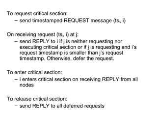
  • 20. • a → b iff ta < tb • Events a and b are causally related iff ta < tb or tb < ta, else they are concurrent • Note that this is still not a total order
  • 21. Causal ordering of messages: application of vector clocks • If send(m1)→ send(m2), then every recipient of both message m1 and m2 must “deliver” m1 before m2. “deliver” – when the message is actually given to the application for processing
  • 22. Birman-Schiper-Stephenson Protocol • To broadcast m from process i, increment Ci(i), and timestamp m with VTm = Ci[i] • When j ≠ i receives m, j delays delivery of m until – Cj[i] = VTm[i] –1 and – Cj[k] ≥ VTm[k] for all k ≠ i – Delayed messaged are queued in j sorted by vector time. Concurrent messages are sorted by receive time. • When m is delivered at j, Cj is updated according to vector clock rule.
  • 23. Problem of Vector Clock • message size increases since each message needs to be tagged with the vector • size can be reduced in some cases by only sending values that have changed
  • 25. Global State Collection Applications: – Checking “stable” properties, checkpoint & recovery Issues: – Need to capture both node and channel states – system cannot be stopped – no global clock
  • 26. Some notations: – LSi : local state of process i – send(mij) : send event of message mij from process i to process j – rec(mij) : similar, receive instead of send – time(x) : time at which state x was recorded – time (send(m)) : time at which send(m) occured
  • 27. send(mij) є LSi iff time(send(mij)) < time(LSi) rec(mij) є LSj iff time(rec(mij)) < time(LSj) transit(LSi,LSj) = { mij | send(mij) є LSi and rec(mij) є LSj} inconsistent(LSi, LSj) = {mij | send(mij) є LSi and
  • 28. Global state: collection of local states GS = {LS1, LS2,…, LSn} GS is consistent iff for all i, j, 1 ≤ i, j ≤ n, inconsistent(LSi, LSj) = Ф GS is transitless iff for all i, j, 1 ≤ i, j ≤ n, transit(LSi, LSj) = Ф
  • 29. Chandy-Lamport’s Algorithm • Uses special marker messages. • One process acts as initiator, starts the state collection by following the marker sending rule below. • Marker sending rule for process P: – P records its state; then for each outgoing channel C from P on which a marker has not been sent already, P sends a marker along C before any further message is sent on C
  • 30. • When Q receives a marker along a channel C: – If Q has not recorded its state then Q records the state of C as empty; Q then follows the marker sending rule – If Q has already recorded its state, it records the state of C as the sequence of messages received along C after Q’s state was recorded and before Q received the marker along C
  • 31. Points to Note: • Markers sent on a channel distinguish messages sent on the channel before the sender recorded its states and the messages sent after the sender recorded its state • The state collected may not be any state that actually happened in reality, rather a state that “could have” happened • Requires FIFO channels • Network should be strongly connected (works obviously for connected, undirected also) • Message complexity O(|E|), where E = no. of links
  • 32. Lai and Young’s Algorithm • Similar to Chandy-Lamport’s, but does not require FIFO • Boolean value X at each node, False indicates state is not recorded yet, True indicates recorded • Value of X piggybacked with every application message • Value of X distinguishes pre-snapshot and post- snapshot messages, similar to the Marker
  • 34. Mutual Exclusion • very well-understood in shared memory systems • Requirements: – at most one process in critical section (safety) – if more than one requesting process, someone enters (liveness) – a requesting process enters within a finite time (no starvation) – requests are granted in order (fairness)
  • 35. Classification of Distributed Mutual Exclusion Algorithms • Non-token based/Permission based – Permission from all processes: e.g. Lamport, Ricart-Agarwala, Raicourol-Carvalho etc. – Permission from a subset: ex. Maekawa • Token based – ex. Suzuki-Kasami
  • 36. Some Complexity Measures • No. of messages/critical section entry • Synchronization delay • Response time • Throughput
  • 37. Lamport’s Algorithm • Every node i has a request queue qi, keeps requests sorted by logical timestamps (total ordering enforced by including process id in the timestamps) To request critical section: – send timestamped REQUEST (tsi, i) to all other nodes – put (tsi, i) in its own queue On receiving a request (tsi, i): – send timestamped REPLY to the requesting node i
  • 38. To enter critical section: – i enters critical section if (tsi, i) is at the top if its own queue, and i has received a message (any message) with timestamp larger than (tsi, i) from ALL other nodes. To release critical section: – i removes it request from its own queue and sends a timestamped RELEASE message to all other nodes – On receiving a RELEASE message from i, i’s request is removed from the local request queue
  • 39. Some points to note: • Purpose of REPLY messages from node i to j is to ensure that j knows of all requests of i prior to sending the REPLY (and therefore, possibly any request of i with timestamp lower than j’s request) • Requires FIFO channels. • 3(n – 1 ) messages per critical section invocation • Synchronization delay = max. message transmission time • requests are granted in order of increasing
  • 40. Ricart-Agarwala Algorithm • Improvement over Lamport’s • Main Idea: – node j need not send a REPLY to node i if j has a request with timestamp lower than the request of i (since i cannot enter before j anyway in this case) • Does not require FIFO • 2(n – 1) messages per critical section invocation • Synchronization delay = max. message transmission time • requests granted in order of increasing timestamps
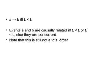
  • 41. To request critical section: – send timestamped REQUEST message (tsi, i) On receiving request (tsi, i) at j: – send REPLY to i if j is neither requesting nor executing critical section or if j is requesting and i’s request timestamp is smaller than j’s request timestamp. Otherwise, defer the request. To enter critical section: – i enters critical section on receiving REPLY from all nodes To release critical section: – send REPLY to all deferred requests
  • 42. Roucairol-Carvalho Algorithm • Improvement over Ricart-Agarwala • Main idea – once i has received a REPLY from j, it does not need to send a REQUEST to j again unless it sends a REPLY to j (in response to a REQUEST from j) – no. of messages required varies between 0 and 2(n – 1) depending on request pattern – worst case message complexity still the same
  • 43. Maekawa’s Algorithm • Permission obtained from only a subset of other processes, called the Request Set (or Quorum) • Separate Request Set Ri for each process i • Requirements: – for all i, j: Ri ∩ Rj ≠ Φ – for all i: i Є Ri – for all i: |Ri| = K, for some K – any node i is contained in exactly D Request Sets, for some D • K = D = sqrt(N) for Maekawa’s
  • 44. A simple version To request critical section: – i sends REQUEST message to all process in Ri On receiving a REQUEST message: – send a REPLY message if no REPLY message has been sent since the last RELEASE message is received. Update status to indicate that a REPLY has been sent. Otherwise, queue up the REQUEST To enter critical section: – i enters critical section after receiving REPLY from all nodes in Ri
  • 45. To release critical section: – send RELEASE message to all nodes in Ri – On receiving a RELEASE message, send REPLY to next node in queue and delete the node from the queue. If queue is empty, update status to indicate no REPLY message has been sent.
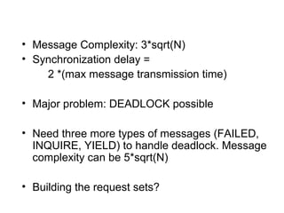
  • 46. • Message Complexity: 3*sqrt(N) • Synchronization delay = 2 *(max message transmission time) • Major problem: DEADLOCK possible • Need three more types of messages (FAILED, INQUIRE, YIELD) to handle deadlock. Message complexity can be 5*sqrt(N) • Building the request sets?
  • 47. Token based Algorithms • Single token circulates, enter CS when token is present • No FIFO required • Mutual exclusion obvious • Algorithms differ in how to find and get the token • Uses sequence numbers rather than timestamps to differentiate between old and current requests
  • 48. Suzuki Kasami Algorithm • Broadcast a request for the token • Process with the token sends it to the requestor if it does not need it Issues: – Current vs. outdated requests – determining sites with pending requests – deciding which site to give the token to
  • 49. • The token: – Queue (FIFO) Q of requesting processes – LN[1..n] : sequence number of request that j executed most recently • The request message: – REQUEST(i, k): request message from node i for its kth critical section execution • Other data structures – RNi[1..n] for each node i, where RNi[j] is the largest sequence number received so far by i in a REQUEST message from j.
  • 50. To request critical section: – If i does not have token, increment RNi[i] and send REQUEST(i, RNi[i]) to all nodes – if i has token already, enter critical section if the token is idle (no pending requests), else follow rule to release critical section On receiving REQUEST(i, sn) fat j: – set RNj[i] = max(RNj[i], sn) – if j has the token and the token is idle, send it to i if RNj[i] = LN[i] + 1. If token is not idle, follow rule to release critical section
  • 51. To enter critical section: – enter CS if token is present To release critical section: – set LN[i] = RNi[i] – For every node j which is not in Q (in token), add node j to Q if RNi[ j ] = LN[ j ] + 1 – If Q is non empty after the above, delete first node from Q and send the token to that node
  • 52. Points to note: – No. of messages: 0 if node holds the token already, n otherwise – Synchronization delay: 0 (node has the token) or max. message delay (token is elsewhere) – No starvation
  • 53. Raymond’s Algorithm • Forms a directed tree (logical) with the token- holder as root • Each node has variable “Holder” that points to its parent on the path to the root. Root’s Holder variable points to itself • Each node i has a FIFO request queue Qi
  • 54. • To request critical section: – Send REQUEST to parent on the tree, provided i does not hold the token currently and Qi is empty. Then place request in Qi • When a non-root node j receives a request from i – place request in Qj – send REQUEST to parent if no previous REQUEST sent
  • 55. • When the root receives a REQUEST: – send the token to the requesting node – set Holder variable to point to that node • When a node receives the token: – delete first entry from the queue – send token to that node – set Holder variable to point to that node – if queue is non-empty, send a REQUEST message to the parent (node pointed at by Holder variable)
  • 56. • To execute critical section: – enter if token is received and own entry is at the top of the queue; delete the entry from the queue • To release critical section – if queue is non-empty, delete first entry from the queue, send token to that node and make Holder variable point to that node – If queue is still non-empty, send a REQUEST message to the parent (node pointed at by Holder variable)
  • 57. Points to note: • Avg. message complexity O(log n) • Sync. delay (T log n)/2, where T = max. message delay
  • 59. Leader Election in Rings • Models – Synchronous or Asynchronous – Anonymous (no unique id) or Non-anonymous (unique ids) – Uniform (no knowledge of ‘n’, the number of processes) or non-uniform (knows ‘n’) • Known Impossibility Result: – There is no Synchronous, non-uniform leader election protocol for anonymous rings – Implications ??
  • 60. Election in Asynchronous Rings Lelann-Chang-Robert’s Algorithm – send own id to node on left – if an id received from right, forward id to left node only if received id greater than own id, else ignore – if own id received, declares itself “leader” • works on unidirectional rings • message complexity = θ(n^2)
  • 61. • Hirschberg-Sinclair Algorithm – operates in phases, requires bidirectional ring – In kth phase, send own id to 2^k processes on both sides of yourself (directly send only to next processes with id and k in it) – if id received, forward if received id greater than own id, else ignore – last process in the chain sends a reply to originator if its id less than received id – replies are always forwarded – A process goes to (k+1)th phase only if it receives a reply from both sides in kth phase – process receiving its own id – declare itself “leader”
  • 62. • Message Complexity: O(nlgn) • Lots of other algorithms exist for rings • Lower Bound Result: – Any comparison-based leader election algorithm in a ring requires Ώ(nlgn) messages – What if not comparison-based?
  • 63. Leader Election in Arbitrary Networks • FloodMax – synchronous, round-based – at each round, each process sends the max. id seen so far (not necessarily its own) to all its neighbors – after diameter no. of rounds, if max. id seen = own id, declares itself leader – Complexity = O(d.m), where d = diameter of the network, m = no. of edges – does not extend to asynchronous model trivially • Variations of building different types of spanning trees with no pre-specified roots. Chosen root at the end is the leader (Ex., the DFS spanning tree algorithm we covered earlier)
  • 65. Clock Synchronization • Multiple machines with physical clocks. How can we keep them more or less synchronized? • Internal vs. External synchronization • Perfect synchronization not possible because of communication delays • Even synchronization within a bound can not be guaranteed with certainty because of unpredictability of communication delays. • But still useful !! Ex. – Kerberos, GPS
  • 66. How clocks work • Computer clocks are crystals that oscillate at a certain frequency • Every H oscillations, the timer chip interrupts once (clock tick). No. of interrupts per second is typically 18.2, 50, 60, 100; can be higher, settable in some cases • The interrupt handler increments a counter that keeps track of no. of ticks from a reference in the past (epoch) • Knowing no. of ticks per second, we can
  • 67. Clock Drift • Unfortunately, period of crystal oscillation varies slightly • If it oscillates faster, more ticks per real second, so clock runs faster; similar for slower clocks • For machine p, when correct reference time is t, let machine clock show time as C = Cp(t) • Ideally, Cp(t) = t for all p, t • In practice, 1 – ρ ≤ dC/dt ≤ 1 + ρ • ρ = max. clock drift rate, usually around 10-5 for cheap oscillators • Drift => Skew between clocks (difference in clock values of two machines)
  • 68. Resynchronization • Periodic resynchronization needed to offset skew • If two clocks are drifting in opposite directions, max. skew after time t is 2 ρ t • If application requires that clock skew < δ, then resynchronization period r < δ /(2 ρ) • Usually ρ and δ are known
  • 69. Cristian’s Algorithm • One m/c acts as the time server • Each m/c sends a message periodically (within resync. period r) asking for current time • Time server replies with its time • Sender sets its clock to the reply • Problems: – message delay – time server time is less than sender’s current time
  • 70. • Handling message delay: try to estimate the time the message with the timer server’s time took to each the sender – measure round trip time and halve it – make multiple measurements of round trip time, discard too high values, take average of rest – make multiple measurements and take minimum – use knowledge of processing time at server if known • Handling fast clocks – do not set clock backwards; slow it down over a period of time to bring in tune with server’s clock
  • 71. Berkeley Algorithm • Centralized as in Cristian’s, but the time server is active • time server asks for time of other m/cs at periodic intervals • time server averages the times and sends the new time to m/cs • M/cs sets their time (advances immediately or slows down slowly) to the new time • Estimation of transmission delay as before
  • 73. • Problem with centralized clk sync: single pt. failure. • Soln: dist. Clk. Sync. • No master clk • All the clks exchanges their clk value among them periodically • Based on these values the system computes the sync. Time & sets its clk.accordingly. • But, some clks may be bad • Bad clks can be identified and handled during sync. By rejecting the time values of any clk which differs by an amount larger than the specified bound. • Another problem: Byzantine clks – two faced clks.
  • 74. • Byzantine clks can transmit diff. values to to diff clks at the same time. • If less than one-third clks are bad or byzantine, then we can have the good clks approx. synchronized. • Scheme: - let there are n clks in the system - each clk periodically broadcasts its time value at the end of certain interval. - suppose the clks are reqd. to be synchronized within є time units.
  • 75. • So, if a clk receives a time value that differs from its own time value by more than є units, it knows it is from a bad clk and hence rejects it. • Each clk averages all good time values & sets its time with this value.
  • 76. External Synchronization • Clocks must be synchronized with real time • Cristian’s algorithm can be used if the time server is synchronized with real time somehow • Berkeley algorithm cannot be used • But what is “real time” anyway?
  • 77. Measurement of time • Astronomical – traditionally used – based on earth’s rotation around its axis and around the sun – solar day : interval between two consecutive transits of the sun – solar second : 1/86,400 of a solar day – period of earth’s rotation varies, so solar second is not stable – mean solar second : average length of large no of solar days, then divide by 86,400
  • 78. • Atomic – based on the transitions of Cesium 133 atom – 1 sec. = time for 9,192,631,770 transitions – about 50+ labs maintain Cesium clock – International Atomic Time (TAI) : mean no. of ticks of the clocks since Jan 1, 1958 – highly stable – But slightly off-sync with mean solar day (since solar day is getting longer) – A leap second inserted approx. occasionally to bring it in sync. (so far 32, all positive) – Resulting clock is called UTC – Universal Coordinated Time
  • 79. • UTC time is broadcast from different sources around the world, ex. – National Institute of Standards & Technology (NIST) – runs radio stations, most famous being WWV, anyone with a proper receiver can tune in – United States Naval Observatory (USNO) – supplies time to all defense sources, among others – National Physical Laboratory in UK – GPS satellites – Many others
  • 80. NTP : Network Time Protocol • Protocol for time sync. in the internet • Hierarchical architecture – primary time servers (stratum 1) synchronize to national time standards via radio, satellite etc. – secondary servers and clients (stratum 2, 3, …) synchronize to primary servers in a hierrachical manner (stratum 2 servers sync. with stratum 1, startum 3 with stratum 2 etc.).
  • 81. • Reliability ensured by redundant servers • Communication by multicast (usually within LAN servers), symmetric (usually within multiple geographically close servers), or client server (to higher stratum servers) • Complex algorithms to combine and filter times • Sync. possible to within tens of milliseconds for most machines • But, just a best-effort service, no guarantees • RFC 1305 and www.eecis.udel.edu/~ntp/ for more details
  • 83. Termination Detection Model – processes can be active or idle – only active processes send messages – idle process can become active on receiving an computation message – active process can become idle at any time – termination: all processes are idle and no computation message are in transit – Can use global snapshot to detect termination also
  • 84. Huang’s Algorithm • One controlling agent, has weight 1 initially • All other processes are idle initially and has weight 0 • Computation starts when controlling agent sends a computation message to a process • An idle process becomes active on receiving a computation message • B(DW) – computation message with weight DW. Can be sent only by the controlling agent or an active process • C(DW) – control message with weight DW, sent by active processes to controlling agent when they are about to become idle
  • 85. Let current weight at process = W 1. Send of B(DW): • Find W1, W2 such that W1 > 0, W2 > 0, W1 + W2 = W • Set W = W1 and send B(W2) 1. Receive of B(DW): • W += DW; • if idle, become active 1. Send of C(DW): • send C(W) to controlling agent • Become idle
  • 87. Building Spanning Trees Applications: • Broadcast • Convergecast • Leader election Two variations: • from a given root r • root is not given a-priori
  • 88. Flooding Algorithm – starts from a given root r – r initiates by sending message M to all neighbours, sets its own parent to nil – For all other nodes, on receiving M from i for the first time, set parent to i and send M to all neighbors except i. Ignore any M received after that – Tree built is an arbitrary spanning tree – Message complexity = 2m – (n -1) where m = no of edges – Time complexity ??
  • 89. Constructing a DFS tree with given root • plain parallelization of the sequential algorithm by introducing synchronization • each node i has a set unexplored, initially contains all neighbors of i • A node i (initiated by the root) considers nodes in unexplored one by one, sending a neighbor j a message M and then waiting for a response (parent or reject) before considering the next node in unexplored • if j has already received M from some other node, j sends a reject to i
  • 90. • else, j sets i as its parent, and considers nodes in its unexplored set one by one • j will send a parent message to i only when it has considered all nodes in its unexplored set • i then considers the next node in its unexplored set • Algorithm terminates when root has received parent or reject message from all its neighbours • Worst case no. of messages = 4m • Time complexity O(m)
  • 91. What if no root given? Main idea: – Nodes have unique ids – A node starts building the DFS tree with itself as root (a single node fragment) spontaneously as in the previous case – Fragments of the spanning tree gets built in parallel, all nodes in each fragment is identified by the id of its root – M carries the fragment id of the sender
  • 92. – when M sent from node in lower id fragment to node in higher id fragment, lower id fragment is stalled by higher id fragment by not giving a response – When M sent from higher to lower id fragment, node in lower id fragment switches parent to node in higher id tree, resets unexplored, and starts DFS again – Eventually, the highest id node becomes the root (leader election!!) – Message complexity O(mn) !! – Time complexity O(m)
  • 93. What about MSTs?? Gallager-Humblet-Spira Algorithm – much more complex! but similar to Kruskal’s – no root given, edge weights assumed to be distinct – MST built up in fragments (subtree of MST) – initially each node in its own fragment – fragments merge, finally just one fragment – outgoing edge – edge that goes between two fragments – known result – min. wt. outgoing edge of a fragment always in MST
  • 94. Issues: 1. How does a node find its min. wt. outgoing edge? 2. How does a fragment finds its min. wt. outgoing edge? 3. When does two fragments merge? 4. How does two fragments merge?
  • 95. Some definitions • Each node has three states – Sleeping – initial state – Find – currently finding the fragment’s min. wt. outgoing edge – Found – found the min. wt. outgoing edge • Each fragment has a level – initially, each node is in a fragment of level 0
  • 96. Merging rule for fragments • Suppose F is a fragment with id X, level L, and min. wt. outgoing edge e. Let fragment at other end of e be F1, with id X1 and level L1. Then – if L < L1, F merges into F1, new fragment has id X1, level L1 – if L=L1, and e is also the min. wt. outgoing edge for F1, then F and F1 merges; new fragment has id X2 = weight of e, and level L + 1; e is called the core edge – otherwise, F waits until one of the above becomes true
  • 97. How to find min. wt. outgoing edge of a fragment • nodes on core edge broadcasts initiate message to all fragment nodes along fragment edges; contains level and id • on receiving initiate, a node find its min. wt. outgoing edge (in Find state) – how? • nodes send Report message with min. wt. edge up towards the core edge along fragment edges (and enters Found state) • leafs send their min. wt. outgoing edge, intermediate nodes send the min. of their min. wt. outgoing edge and min. edge sent by children in fragment; path info to best edge kept
  • 98. What then??? • nodes on core edges send Change_core message to node i with min. wt. outgoing edge • node i then sends a Connect message to node j at other end with its level • If j’s fragment level is greater than i’s, initiate message sent from j to i. This updates level and id of all nodes in j’s old fragment; if j has not sent a Report message yet, nodes in i’s old fragment starts finding its min. wt. outgoing edge, else not. • if j’s fragment level is less, no response sent and i just waits till j’s fragment id becomes higher • if fragment id’s match and j sends Connect to i also, merge into a level L+1 fragment with new core edge and id, and send initiate message
  • 99. • some more details skipped, read paper • Algo. terminates when no outgoing edge found for a fragment • Worst case message complexity = O(n log n + m)
  • 101. Fault Tolerance & Recovery Classification of faults: – based on component that failed • program/process • processor/machine • link • storage • clock – based on behavior of faulty component • Crash – just halts • Failstop – crash with additional conditions • Omission – fails to perform some steps • Byzantine – behaves arbitrarily • Timing – violates timing constraints
  • 102. Types of tolerance: – Masking – system always behaves as per specifications even in presence of faults – Non-masking – system may violate specifications in presence of faults. Should at least behave in a well-defined manner Fault tolerant system should specify: – Class of faults tolerated – what tolerance is given from each class
  • 103. Some building blocks (assumptions/primitives that help in designing fault tolerant systems): – Agreement (multiple processes agree on some value) – Clock synchronization – Stable storage (data accessible after crash) – Reliable communication (point-to-point, broadcast, multicast) – Atomic actions
  • 104. Agreement Problems Model: – total n processes, at most m of which can be faulty – reliable communication medium – fully connected – receiver always knows the identity of the sender of a message – byzantine faults – synchronous system. In each round, a process receives messages, performs computation, and sends messages.
  • 105. Different problem variations • Byzantine agreement (or Byzantine Generals problem) – one process x broadcasts a value v • all nonfaulty processes must agree on a common value (Agreement condition). • The agreed upon value must be v if x is nonfaulty (Validity condition) • Consensus – Each process broadcasts its initial value • satisfy agreement condition • If initial value of all nonfaulty processes is v, then the agreed upon value must be v
  • 106. • Interactive Consistency – Each process i broadcasts its own value vi • all nonfaulty processes agree on a common vector (v1, v2,…,vn) • If the ith process is nonfaulty, then the ith value in the vector agreed upon by nonfaulty processes must be vi Solution to Byzantine agreement problem implies solution to other two
  • 107. Byzantine Agreement Problem • no solution possible if – asynchronous system, or – n < (3m + 1) • needs at least (m+1) rounds of message exchange (lower bound result) • “Oral” messages – messages can be forged/changed in any manner, but the receiver always knows the sender
  • 108. Lamport-Shostak-Pease Algorithm Recursively defined; OM(m), m > 0 • Source x broadcasts value to all processes • Let vi = value received by process i from source (0 if no value received). Process i acts as a new source and initiates OM(m -1), sending vi to remaining (n - 2) processes • For each i, j, i ≠ j, let vj = value received by process i from process j in step 2 using O(m- 1). Process i uses the value majority(v1, v2, …, vn -1)
  • 109. OM(0) 1. Source x broadcasts value to all processes 2. Each process uses the value; if no value received, 0 is used Time complexity = m+1 rounds Message Complexity = O(nm ) You can reduce message complexity to polynomial by increasing time
  • 110. Atomic Actions and Commit Protocols An action may have multiple subactions executed by different processes at different nodes of a distributed system Atomic action : either all subactions are done or none are done (all-or-nothing property/ global atomicity property) as far as system state is concerned Commit protocols – protocols for enforcing global atomicity property
  • 111. Two-Phase Commit • Assumes the presence of write-ahead log at each process to recover from local crashes • One process acts as coordinator Phase 1: • coordinator sends COMMIT_REQUEST to all processes • waits for replies from all processes • on receiving a COMMIT_REQUEST, a process, if the local transaction is successful, writes Undo/redo logs in stable storage, and sends an AGREED message to the coordinator. Otherwise, sends an ABORT
  • 112. Phase 2: • If all processes reply AGREED, coordinator writes COMMIT record into the log, then sends COMMIT to all processes. If at least one process has replied ABORT, coordinator sends ABORT to all. Coordinator then waits for ACK from all processes. If ACK is not received within timeout period, resend. If all ACKs are received, coordinator writes COMPLETE to log • On receiving a COMMIT, a process releases all resources/locks, and sends an ACK to coordinator • On receiving an ABORT, a process undoes the transaction using Undo log, releases all resources/locks, and sends an ACK
  • 113. • Ensures global atomicity; either all processes commit or all of them aborts • Resilient to crash failures (see text for different scenarios of failure) • Blocking protocol – crash of coordinator can block all processes • Non-blocking protocols possible; ex., Three-Phase Commit protocol; we will not discuss in this class
  • 114. Checkpointing & Rollback Recovery Error recovery: • Forward error recovery – assess damage due to faults exactly and repair the erroneous part of the system state – less overhead but hard to assess effect of faults exactly in general • Backward error recovery – on a fault, restore system state to a previous error-free state and restart from there – costlier, but more general, application- independent technique
  • 115. Checkpoint and Rollback Recovery – a form of backward error recovery Checkpoint : – local checkpoint – local state of a process saved in stable storage for possible rollback on a fault – global checkpoint – collection of local checkpoints, one from each process Consistent and Strongly Consistent Global Checkpoint – similar to consistent and strongly consistent global state respectively (Also called “recovery line”)
  • 116. Orphan message – a message whose receive is recorded in some local checkpoint of a global checkpoint but send is not recorded in any local checkpoint in that global checkpoint ( Note : A consistent global checkpoint cannot have an orphan message) Lost message – a message whose send is recorded but receive is not in a global checkpoint Is lost messages a problem?? – not if unreliable channels assumed (since messages can be lost anyway) – if reliable channels assumed, need to handle this properly! Cannot lose messages ! – We will assume unreliable channels for
  • 117. Performance measures for a checkpointing and recovery algorithm • during fault-free operation – checkpointing time – space for storing checkpoints and messages (if needed) • in case of a fault – recovery time (time to establish recovery line) – extent of rollback (how far in the past did we roll back? how much computation is lost?) – is output commit problem handled? (if an output was sent out before the fault, say cash dispensed at a teller m/c, it should not be resent after restarting after the fault)
  • 118. Some parameters that affect performance • Checkpoint interval (time between two successive checkpoints) • Number of processes • Communication pattern of the application • Fault frequency • Nature of stable storage
  • 119. Classification of Checkpoint & Recovery Algorithms • Asynchronous/Uncoordinated – every process takes local checkpoint independently – to recover from a fault in one process, all processes coordinate to find a consistent global checkpoint from their local checkpoints – very low fault-free overhead, recovery overhead is high – Domino effect possible (no consistent global checkpoint exist, so all processes have to restart from scratch) – higher space requirements, as all local checkpoints need to be kept – Good for systems where fault is rare and inter- process communication is not too high (less chance
  • 120. • Synchronous/Coordinated – all processes coordinate to take a consistent global checkpoint – during recovery, every process just rolls back to its last local checkpoint independently – low recovery overhead, but high checkpointing overhead – no domino effect possible – low space requirement, since only last checkpoint needs to be stored at each process
  • 121. • Communication Induced – Synchronize checkpointing with communication, since message send/receive is the fundamental cause of inconsistency in global checkpoint – Ex. : take local checkpoint right after every send! Last local checkpoint at each process is always consistent. But too costly – Many variations are there, more efficient than the above, we will not discuss them in this class.
  • 122. • Message logging – Take coordinated or uncoordinated checkpoint, and then log (in stable storage) all messages received since the last checkpoint – On recovery, only the recovering process goes back to its last checkpoint, and then replays messages from the log appropriately until it reaches the state right before the fault – Only class that can handle output commit problem! – Details too complex to discuss in this class
  • 123. Some Checkpointing Algorithms Asynchronous/Uncoordinated – See Juang-Venkatesan’s algorithm in text, quite well-explained Synchronous/Coordinated – Chandy-Lamport’s global state collection algorithm can be modified to handle recovery from faults – See Koo-Toueg’s algorithm in text, quite well- explained