SlideShare a Scribd company logo
SQL – Day 1
Database
• A database is an organized collection of information/data
• Common examples of a database would be a library management system,
hospital management system etc
Database Terminology
• Table - a list of related information presented in a column/row format
• Row is referred to as a Record
• Column in a table is a category of information referred to as a Field
Database Terminologies
Users
• Used by various users for various purposes
• Designers - group of people who actually works on designing part of
database.
• Administrators - bunch of users who maintain the DBMS and are
responsible for administrating the database.
• End users - people who actually take advantage of database system
Architecture
• design of a Database Management System highly depends on its
architecture
• DBMS architecture can be seen as single tier or multi tier
• In 1-tier architecture, DBMS is the only entity where user directly sits on
DBMS and uses it
• If the architecture of DBMS is 2-tier then must have some application,
which uses the DBMS. Programmers use 2-tier architecture where they
access DBMS by means of application.
3-tier architecture
• Most widely used architecture
• Multiple tier database architecture is highly
modifiable as almost all its components are
independent and can be changed
independently
3-tier architecture
• Database (Data) Tier: At this tier, only database resides. Database along
with its query processing languages sits in layer-3 of 3-tier architecture. It
also contains all relations and their constraints.
• Application (Middle) Tier: At this tier the application server and program,
which access database, resides. For a user this application tier works as
abstracted view of database. Users are unaware of any existence of
database beyond application. For database-tier, application tier is the user
of it. Database tier is not aware of any other user beyond application tier.
This tier works as mediator between the two.
• User (Presentation) Tier: An end user sits on this tier. From a users aspect
this tier is everything. He/she doesn't know about any existence or form of
database beyond this layer. At this layer multiple views of database can be
provided by the application. All views are generated by applications, which
resides in application tier.
Data Models
• Data model tells how the logical structure of a database is modeled
• Data models define how data is connected to each other and how it will
be processed and stored inside the system
Entity-Relationship Model
• Entity-Relationship model formulates real-world scenario into database
model
• ER Model is best used for the conceptual design of database.
• ER Model is based on:
– Entities and their attributes
– Relationships among entities
Entity-Relationship Model
• Entity
– An entity in ER Model is real world entity, which has some properties
called attributes. Every attribute is defined by its set of values,
called domain.
– For example, in a school database, a student is considered as an entity.
Student has various attributes like name, age and class etc.
• Relationship
– The logical association among entities is called relationship.
Relationships are mapped with entities in various ways. Mapping
cardinalities define the number of association between two entities.
– Mapping cardinalities:
• one to one
• one to many
• many to one
• many to many
Database schema
• skeleton structure of a database
• tells about how the data is organized and how relation among them is
associated
• Database schema is a descriptive detail of the database, which can be
depicted by means of schema diagrams.
• All these activities are done by database designer to help programmers in
order to give some ease of understanding all aspect of database.
Database schema
• Database schema can be divided broadly in two categories:
• Physical Database Schema: This schema pertains to the actual storage of
data and its form of storage like files, indices etc. It defines how data will
be stored in secondary storage etc.
• Logical Database Schema: This defines all logical constraints that need to
be applied on data stored. It defines tables, views and integrity constraints
etc.
Database Instance
• Database schema is the skeleton of database. It is designed when
database doesn't exist at all and very hard to do any changes once the
database is operational. Database schema does not contain any data or
information
• Database instances is a snapshot of database. It tend to change with time.
DBMS ensures that its every instance (state) must be a valid state by
keeping up to all validation, constraints and condition that database
designers has imposed or it is expected from DBMS itself.
Data Independence
• Logical Data Independence
– Logical data is data about database, that is, it stores information about
how data is managed inside. For example, a table (relation) stored in
the database and all constraints, which are applied on that relation.
– Logical data independence is a kind of mechanism, which liberalizes
itself from actual data stored on the disk. If we do some changes on
table format it should not change the data residing on disk.
• Physical Data Independence
– All schemas are logical and actual data is stored in bit format on the
disk. Physical data independence is the power to change the physical
data without impacting the schema or logical data.
– For example, in case we want to change or upgrade the storage system
itself, that is, using SSD instead of Hard-disks should not have any
impact on logical data or schemas.
ENTITY-SET AND KEYS
• Key is an attribute or collection of attributes that uniquely identifies an
entity among entity set.
• For example, roll_number of a student makes her/him identifiable among
students.
• Super Key: Set of attributes (one or more) that collectively identifies an
entity in an entity set.
• Candidate Key: Minimal super key is called candidate key that is, super
keys for which no proper subset are a super key. An entity set may have
more than one candidate key.
• Primary Key: This is one of the candidate key chosen by the database
designer to uniquely identify the entity set.
Relationship
• The association among entities is called relationship.
• For example, employee entity works_at a department.
• Another example is student who enrolls in some course.
• Here, Works_at and Enrolls are called relationship.
MAPPING CARDINALITIES
• Cardinality defines the number of entities in one entity set which can be
associated to the number of entities of other set via relationship set.
One-to-one
• one entity from entity set A can be associated with at most one entity of
entity set B and vice versa.
One-to-many
• One entity from entity set A can be associated with more than one entities
of entity set B but from entity set B one entity can be associated with at
most one entity.
Many-to-one
• More than one entities from entity set A can be associated with at most
one entity of entity set B but one entity from entity set B can be
associated with more than one entity from entity set A.
Many-to-many
• one entity from A can be associated with more than one entity from B and
vice versa.
ER Diagram Representation
• Entity
– Entities are represented by means of rectangles. Rectangles are
named with the entity set they represent.
ER Diagram Representation
• Attributes
– Attributes are properties of entities. Attributes are represented by
means of eclipses. Every eclipse represents one attribute and is
directly connected to its entity (rectangle).
ER Diagram Representation
• Composite attributes are further divided in a tree like structure. Every
node is then connected to its attribute. That is composite attributes are
represented by eclipses that are connected with an eclipse.
ER Diagram Representation
• Multivalued attributes are depicted by double eclipse.
ER Diagram Representation
• Derived attributes are depicted by dashed eclipse.
ER Diagram Representation
• Relationships are represented by diamond shaped box. Name of the
relationship is written in the diamond-box. All entities (rectangles),
participating in relationship, are connected to it by a line.
ER Diagram Representation
• One-to-one - When only one instance of entity is associated with the
relationship, it is marked as '1'. This image below reflects that only 1
instance of each entity should be associated with the relationship.
ER Diagram Representation
• One-to-many - When more than one instance of entity is associated with
the relationship, it is marked as 'N'. This image below reflects that only 1
instance of entity on the left and more than one instance of entity on the
right can be associated with the relationship.
ER Diagram Representation
• Many-to-one - When more than one instance of entity is associated with
the relationship, it is marked as 'N'. This image below reflects that more
than one instance of entity on the left and only one instance of entity on
the right can be associated with the relationship.
ER Diagram Representation
• Many-to-many - This image below reflects that more than one instance of
entity on the left and more than one instance of entity on the right can be
associated with the relationship.
ER Diagram Representation
• PARTICIPATION CONSTRAINTS
– Total Participation: Each entity in the entity is involved in the
relationship. Total participation is represented by double lines.
– Partial participation: Not all entities are involved in the relation ship.
Partial participation is represented by single line.
Codd's 12 Rules
• Dr Edgar F. Codd did some extensive research in Relational Model of
database systems and came up with twelve rules of his own which
according to him, a database must obey in order to be a true relational
database.
Codd's 12 Rules
• Rule 1: Information rule
– This rule states that all information (data), which is stored in the
database, must be a value of some table cell. Everything in a database
must be stored in table formats. This information can be user data or
meta-data.
• Rule 2: Guaranteed Access rule
– This rule states that every single data element (value) is guaranteed to
be accessible logically with combination of table-name, primary-key
(row value) and attribute-name (column value). No other means, such
as pointers, can be used to access data.
Codd's 12 Rules
• Rule 3: Systematic Treatment of NULL values
– This rule states the NULL values in the database must be given a
systematic treatment. As a NULL may have several meanings, i.e. NULL
can be interpreted as one the following: data is missing, data is not
known, data is not applicable etc.
• Rule 4: Active online catalog
– This rule states that the structure description of whole database must
be stored in an online catalog, i.e. data dictionary, which can be
accessed by the authorized users. Users can use the same query
language to access the catalog which they use to access the database
itself.
Codd's 12 Rules
• Rule 5: Comprehensive data sub-language rule
– This rule states that a database must have a support for a language
which has linear syntax which is capable of data definition, data
manipulation and transaction management operations. Database can
be accessed by means of this language only, either directly or by
means of some application. If the database can be accessed or
manipulated in some way without any help of this language, it is then
a violation.
• Rule 6: View updating rule
– This rule states that all views of database, which can theoretically be
updated, must also be updatable by the system.
Codd's 12 Rules
• Rule 7: High-level insert, update and delete rule
– This rule states the database must employ support high-level
insertion, updation and deletion. This must not be limited to a single
row that is, it must also support union, intersection and minus
operations to yield sets of data records.
• Rule 8: Physical data independence
– This rule states that the application should not have any concern
about how the data is physically stored. Also, any change in its physical
structure must not have any impact on application.
Codd's 12 Rules
• Rule 9: Logical data independence
– This rule states that the logical data must be independent of its user’s
view (application). Any change in logical data must not imply any
change in the application using it. For example, if two tables are
merged or one is split into two different tables, there should be no
impact the change on user application. This is one of the most difficult
rule to apply.
• Rule 10: Integrity independence
– This rule states that the database must be independent of the
application using it. All its integrity constraints can be independently
modified without the need of any change in the application. This rule
makes database independent of the front-end application and its
interface.
Codd's 12 Rules
• Rule 11: Distribution independence
– This rule states that the end user must not be able to see that the data
is distributed over various locations. User must also see that data is
located at one site only. This rule has been proven as a foundation of
distributed database systems.
• Rule 12: Non-subversion rule
– This rule states that if a system has an interface that provides access to
low level records, this interface then must not be able to subvert the
system and bypass security and integrity constraints.
Constraints
• Every relation has some conditions that must hold for it to be a valid
relation. These conditions are called Relational Integrity Constraints.
• There are three main integrity constraints.
– Key Constraints
– Domain constraints
– Referential integrity constraints
Constraints
• KEY CONSTRAINTS:
– There must be at least one minimal subset of attributes in the relation,
which can identify a record uniquely. This minimal subset of attributes
is called key for that relation. If there are more than one such minimal
subsets, these are called candidate keys.
• Key constraints forces that:
– in a relation with a key attribute, no two tuples can have identical
value for key attributes.
– key attribute can not have NULL values.
• Key constrains are also referred to as Entity Constraints.
Constraints
• DOMAIN CONSTRAINTS
– Attributes have specific values in real-world scenario.
– Every attribute is bound to have a specific range of values.
– For example, age can only be positive integer and telephone number
cannot be outside 0-9.
Constraints
• REFERENTIAL INTEGRITY CONSTRAINTS
– This integrity constraints works on the concept of Foreign Key. A key
attribute of a relation can be referred in other relation, where it is
called foreign key.
– Referential integrity constraint states that if a relation refers to an key
attribute of a different or same relation, that key element must exists.
Normalization
• If a database design is not perfect it may contain anomalies, which are like
a bad dream for database itself. Managing a database with anomalies is
next to impossible.
– Update anomalies: if data items are scattered and are not linked to
each other properly, then there may be instances when we try to
update one data item that has copies of it scattered at several places,
few instances of it get updated properly while few are left with there
old values. This leaves database in an inconsistent state.
– Deletion anomalies: we tried to delete a record, but parts of it left
undeleted because of unawareness, the data is also saved somewhere
else.
– Insert anomalies: we tried to insert data in a record that does not
exist at all.
• Normalization is a method to remove all these anomalies and bring
database to consistent state and free from any kinds of anomalies.
Normalization
• First Normal Form:
– This is defined in the definition of relations (tables) itself. This rule
defines that all the attributes in a relation must have atomic domains.
Values in atomic domain are indivisible units.
– all repeating group columns on a single primary key are split into a
separate relationship leaving behind the primary key column in the
other relation to form a composite primary key
First Normal Form (1NF)
Normalization
• Second Normal Form:
• Before we learn about second normal form, we need to understand the
following:
– Prime attribute: an attribute, which is part of prime-key, is prime
attribute.
– Non-prime attribute: an attribute, which is not a part of prime-key, is
said to be a non-prime attribute.
• Second normal form says, that every non-prime attribute should be fully
functionally dependent on prime key attribute. That is, if X → A holds,
then there should not be any proper subset Y of X, for that Y → A also
holds.
• For those with compound (or composite) primary key, examine every non
key column and ask whether it depends on whole of the compound key or
just on some part of it.
• Remove those that depend only on some part of the key to a new relation
with that part as the primary key.
Second Normal Form (2NF)
Normalization
• Third Normal Form:
• For a relation to be in Third Normal Form, it must be in Second Normal
form and the following must satisfy:
• No non-prime attribute is transitively dependent on prime key attribute
• For any non-trivial functional dependency, X → A, then either X is a
superkey or, A is prime attribute.
• Examine every non key column and question its relationship with other
non key column.
• In the previous example, CustName and CustAddr depends on CustNo,
which depends on OrderNo
• So CustName and CustAddr transitively (or indirectly) depend on OrderNo
and hence should be separated as a new relation.
Third Normal Form (3NF)
Normalization
First Normal Form
Second Normal Form
Third Normal Form
SQL Overview
• SQL is a programming language for Relational Databases
• SQL comprises both data definition and data manipulation languages.
• Using the data definition properties of SQL, one can design and modify
database schema whereas data manipulation properties allows SQL to
store and retrieve data from database.
Data definition Language
• CREATE
– Creates new databases, tables and views from RDBMS
• For example:
– Create database tutorialspoint;
– Create table article;
– Create view for_students;
Data definition Language
• DROP
• Drop commands deletes views, tables and databases from RDBMS
– Drop object_type object_name;
– Drop database tutorialspoint;
– Drop table article;
– Drop view for_students;
Data definition Language
• ALTER
• Modifies database schema.
• Alter object_type, object_name parameters;
• for example:
– Alter table article add subject varchar;
• This command adds an attribute in relation article with name subject of
string type.
Data Manipulation Language
• SQL is equipped with data manipulation language. DML modifies the
database instance by inserting, updating and deleting its data.
• DML is responsible for all data modification in databases. SQL contains the
following set of command in DML section:
– SELECT/FROM/WHERE
– INSERT INTO/VALUES
– UPDATE/SET/WHERE
– DELETE FROM/WHERE
• These basic constructs allows database programmers and users to enter
data and information into the database and retrieve efficiently using a
number of filter options.
Data Manipulation Language
• SELECT/FROM/WHERE
• SELECT
• This is one of the fundamental query command of SQL. It is similar to
projection operation of relational algebra. It selects the attributes based
on the condition described by WHERE clause.
• FROM
• This clause takes a entity name as an argument from which attributes are
to be selected/projected. In case more than one entity names are given
this clause corresponds to cartesian product.
• WHERE
• This clause defines predicate or conditions which must match in order to
qualify the attributes to be projected.
• For example: Select author_name From book_author Where age > 50;This
command will project names of author’s from book_author entity whose
age is greater than 50.
Data Manipulation Language
• INSERT INTO/VALUES
• This command is used for inserting values into rows of table (relation).
• Syntax -
• INSERT INTO table (column1 [, column2, column3 ... ]) VALUES (value1 [,
value2, value3 ... ])
• INSERT INTO table VALUES (value1, [value2, ... ])
• For Example:
• INSERT INTO tutorialspoint (Author, Subject) VALUES ("anonymous",
"computers");
Data Manipulation Language
• UPDATE/SET/WHERE
• This command is used for updating or modifying values of columns of
table (relation).
• Syntax is
• UPDATE table_name SET column_name = value [, column_name = value
...] [WHERE condition]
• For example:
• UPDATE tutorialspoint SET Author="webmaster" WHERE
Author="anonymous";
Data Manipulation Language
• DELETE/FROM/WHERE
• This command is used for removing one or more rows from table
(relation).
• Syntax is
• DELETE FROM table_name [WHERE condition];
• For example:
• DELETE FROM tutorialspoints WHERE Author="unknown";

More Related Content

Similar to SQL Tutorial - Basics of Structured Query Language Day 1.pdf (20)

PPTX
ER modeling
Dabbal Singh Mahara
 
PPTX
Unit-1-DBMS-SUN-4 everything you need to know.pptx
nirajsharmapuneiat
 
PPTX
Database Management System
SelshaCs
 
PPTX
Revision ch 3
Rupali Rana
 
PPTX
DBMS_Data Model,Keys,Attributes,Relationship.pptx
DrThenmozhiKarunanit
 
PDF
Db lec 01
Ramadan Babers, PhD
 
PPT
ermodelN in database management system.ppt
urvashipundir04
 
PDF
Db lec 02_new
Ramadan Babers, PhD
 
PDF
Unit1 rdbms study_materials-converted (1) (1)
gayaramesh
 
PDF
Unit1 rdbms study_materials
gayaramesh
 
PPTX
Entity Relationship Model
Slideshare
 
PPTX
Day 1 SQL.pptx
raghuKatagall1
 
PPTX
SQL.pptx
raghuKatagall1
 
PPTX
Data Models and Relational Database Design.pptx
niqqaanonymous211
 
PPTX
Unit 2_DBMS_10.2.22.pptx
MaryJoseph79
 
PPTX
DBMS-Unit-1.pptx
Bhavya304221
 
PPTX
parth presentation
CA Parth Kanabar
 
PDF
Chapter – 2 Data Models.pdf
TamiratDejene1
 
PDF
Advance database system(part 4)
Abdullah Khosa
 
PDF
Relational data base management system (Unit 1)
Ismail Mukiibi
 
ER modeling
Dabbal Singh Mahara
 
Unit-1-DBMS-SUN-4 everything you need to know.pptx
nirajsharmapuneiat
 
Database Management System
SelshaCs
 
Revision ch 3
Rupali Rana
 
DBMS_Data Model,Keys,Attributes,Relationship.pptx
DrThenmozhiKarunanit
 
ermodelN in database management system.ppt
urvashipundir04
 
Db lec 02_new
Ramadan Babers, PhD
 
Unit1 rdbms study_materials-converted (1) (1)
gayaramesh
 
Unit1 rdbms study_materials
gayaramesh
 
Entity Relationship Model
Slideshare
 
Day 1 SQL.pptx
raghuKatagall1
 
SQL.pptx
raghuKatagall1
 
Data Models and Relational Database Design.pptx
niqqaanonymous211
 
Unit 2_DBMS_10.2.22.pptx
MaryJoseph79
 
DBMS-Unit-1.pptx
Bhavya304221
 
parth presentation
CA Parth Kanabar
 
Chapter – 2 Data Models.pdf
TamiratDejene1
 
Advance database system(part 4)
Abdullah Khosa
 
Relational data base management system (Unit 1)
Ismail Mukiibi
 

Recently uploaded (20)

PPTX
apidays Helsinki & North 2025 - Vero APIs - Experiences of API development in...
apidays
 
PDF
apidays Helsinki & North 2025 - APIs in the healthcare sector: hospitals inte...
apidays
 
PPT
AI Future trends and opportunities_oct7v1.ppt
SHIKHAKMEHTA
 
PDF
apidays Singapore 2025 - Trustworthy Generative AI: The Role of Observability...
apidays
 
PPTX
apidays Helsinki & North 2025 - Agentic AI: A Friend or Foe?, Merja Kajava (A...
apidays
 
PDF
NIS2 Compliance for MSPs: Roadmap, Benefits & Cybersecurity Trends (2025 Guide)
GRC Kompas
 
PPTX
apidays Singapore 2025 - Designing for Change, Julie Schiller (Google)
apidays
 
PDF
apidays Singapore 2025 - The API Playbook for AI by Shin Wee Chuang (PAND AI)
apidays
 
PPT
tuberculosiship-2106031cyyfuftufufufivifviviv
AkshaiRam
 
PPTX
apidays Singapore 2025 - Generative AI Landscape Building a Modern Data Strat...
apidays
 
PDF
apidays Helsinki & North 2025 - API-Powered Journeys: Mobility in an API-Driv...
apidays
 
PDF
The European Business Wallet: Why It Matters and How It Powers the EUDI Ecosy...
Lal Chandran
 
PDF
OOPs with Java_unit2.pdf. sarthak bookkk
Sarthak964187
 
PDF
OPPOTUS - Malaysias on Malaysia 1Q2025.pdf
Oppotus
 
PDF
Avatar for apidays apidays PRO June 07, 2025 0 5 apidays Helsinki & North 2...
apidays
 
PDF
apidays Helsinki & North 2025 - Monetizing AI APIs: The New API Economy, Alla...
apidays
 
PPTX
Listify-Intelligent-Voice-to-Catalog-Agent.pptx
nareshkottees
 
PPTX
Advanced_NLP_with_Transformers_PPT_final 50.pptx
Shiwani Gupta
 
PDF
Driving Employee Engagement in a Hybrid World.pdf
Mia scott
 
PDF
apidays Singapore 2025 - Surviving an interconnected world with API governanc...
apidays
 
apidays Helsinki & North 2025 - Vero APIs - Experiences of API development in...
apidays
 
apidays Helsinki & North 2025 - APIs in the healthcare sector: hospitals inte...
apidays
 
AI Future trends and opportunities_oct7v1.ppt
SHIKHAKMEHTA
 
apidays Singapore 2025 - Trustworthy Generative AI: The Role of Observability...
apidays
 
apidays Helsinki & North 2025 - Agentic AI: A Friend or Foe?, Merja Kajava (A...
apidays
 
NIS2 Compliance for MSPs: Roadmap, Benefits & Cybersecurity Trends (2025 Guide)
GRC Kompas
 
apidays Singapore 2025 - Designing for Change, Julie Schiller (Google)
apidays
 
apidays Singapore 2025 - The API Playbook for AI by Shin Wee Chuang (PAND AI)
apidays
 
tuberculosiship-2106031cyyfuftufufufivifviviv
AkshaiRam
 
apidays Singapore 2025 - Generative AI Landscape Building a Modern Data Strat...
apidays
 
apidays Helsinki & North 2025 - API-Powered Journeys: Mobility in an API-Driv...
apidays
 
The European Business Wallet: Why It Matters and How It Powers the EUDI Ecosy...
Lal Chandran
 
OOPs with Java_unit2.pdf. sarthak bookkk
Sarthak964187
 
OPPOTUS - Malaysias on Malaysia 1Q2025.pdf
Oppotus
 
Avatar for apidays apidays PRO June 07, 2025 0 5 apidays Helsinki & North 2...
apidays
 
apidays Helsinki & North 2025 - Monetizing AI APIs: The New API Economy, Alla...
apidays
 
Listify-Intelligent-Voice-to-Catalog-Agent.pptx
nareshkottees
 
Advanced_NLP_with_Transformers_PPT_final 50.pptx
Shiwani Gupta
 
Driving Employee Engagement in a Hybrid World.pdf
Mia scott
 
apidays Singapore 2025 - Surviving an interconnected world with API governanc...
apidays
 
Ad

SQL Tutorial - Basics of Structured Query Language Day 1.pdf

  • 2. Database • A database is an organized collection of information/data • Common examples of a database would be a library management system, hospital management system etc Database Terminology • Table - a list of related information presented in a column/row format • Row is referred to as a Record • Column in a table is a category of information referred to as a Field
  • 4. Users • Used by various users for various purposes • Designers - group of people who actually works on designing part of database. • Administrators - bunch of users who maintain the DBMS and are responsible for administrating the database. • End users - people who actually take advantage of database system
  • 5. Architecture • design of a Database Management System highly depends on its architecture • DBMS architecture can be seen as single tier or multi tier • In 1-tier architecture, DBMS is the only entity where user directly sits on DBMS and uses it • If the architecture of DBMS is 2-tier then must have some application, which uses the DBMS. Programmers use 2-tier architecture where they access DBMS by means of application.
  • 6. 3-tier architecture • Most widely used architecture • Multiple tier database architecture is highly modifiable as almost all its components are independent and can be changed independently
  • 7. 3-tier architecture • Database (Data) Tier: At this tier, only database resides. Database along with its query processing languages sits in layer-3 of 3-tier architecture. It also contains all relations and their constraints. • Application (Middle) Tier: At this tier the application server and program, which access database, resides. For a user this application tier works as abstracted view of database. Users are unaware of any existence of database beyond application. For database-tier, application tier is the user of it. Database tier is not aware of any other user beyond application tier. This tier works as mediator between the two. • User (Presentation) Tier: An end user sits on this tier. From a users aspect this tier is everything. He/she doesn't know about any existence or form of database beyond this layer. At this layer multiple views of database can be provided by the application. All views are generated by applications, which resides in application tier.
  • 8. Data Models • Data model tells how the logical structure of a database is modeled • Data models define how data is connected to each other and how it will be processed and stored inside the system
  • 9. Entity-Relationship Model • Entity-Relationship model formulates real-world scenario into database model • ER Model is best used for the conceptual design of database. • ER Model is based on: – Entities and their attributes – Relationships among entities
  • 10. Entity-Relationship Model • Entity – An entity in ER Model is real world entity, which has some properties called attributes. Every attribute is defined by its set of values, called domain. – For example, in a school database, a student is considered as an entity. Student has various attributes like name, age and class etc. • Relationship – The logical association among entities is called relationship. Relationships are mapped with entities in various ways. Mapping cardinalities define the number of association between two entities. – Mapping cardinalities: • one to one • one to many • many to one • many to many
  • 11. Database schema • skeleton structure of a database • tells about how the data is organized and how relation among them is associated • Database schema is a descriptive detail of the database, which can be depicted by means of schema diagrams. • All these activities are done by database designer to help programmers in order to give some ease of understanding all aspect of database.
  • 12. Database schema • Database schema can be divided broadly in two categories: • Physical Database Schema: This schema pertains to the actual storage of data and its form of storage like files, indices etc. It defines how data will be stored in secondary storage etc. • Logical Database Schema: This defines all logical constraints that need to be applied on data stored. It defines tables, views and integrity constraints etc.
  • 13. Database Instance • Database schema is the skeleton of database. It is designed when database doesn't exist at all and very hard to do any changes once the database is operational. Database schema does not contain any data or information • Database instances is a snapshot of database. It tend to change with time. DBMS ensures that its every instance (state) must be a valid state by keeping up to all validation, constraints and condition that database designers has imposed or it is expected from DBMS itself.
  • 14. Data Independence • Logical Data Independence – Logical data is data about database, that is, it stores information about how data is managed inside. For example, a table (relation) stored in the database and all constraints, which are applied on that relation. – Logical data independence is a kind of mechanism, which liberalizes itself from actual data stored on the disk. If we do some changes on table format it should not change the data residing on disk. • Physical Data Independence – All schemas are logical and actual data is stored in bit format on the disk. Physical data independence is the power to change the physical data without impacting the schema or logical data. – For example, in case we want to change or upgrade the storage system itself, that is, using SSD instead of Hard-disks should not have any impact on logical data or schemas.
  • 15. ENTITY-SET AND KEYS • Key is an attribute or collection of attributes that uniquely identifies an entity among entity set. • For example, roll_number of a student makes her/him identifiable among students. • Super Key: Set of attributes (one or more) that collectively identifies an entity in an entity set. • Candidate Key: Minimal super key is called candidate key that is, super keys for which no proper subset are a super key. An entity set may have more than one candidate key. • Primary Key: This is one of the candidate key chosen by the database designer to uniquely identify the entity set.
  • 16. Relationship • The association among entities is called relationship. • For example, employee entity works_at a department. • Another example is student who enrolls in some course. • Here, Works_at and Enrolls are called relationship.
  • 17. MAPPING CARDINALITIES • Cardinality defines the number of entities in one entity set which can be associated to the number of entities of other set via relationship set.
  • 18. One-to-one • one entity from entity set A can be associated with at most one entity of entity set B and vice versa.
  • 19. One-to-many • One entity from entity set A can be associated with more than one entities of entity set B but from entity set B one entity can be associated with at most one entity.
  • 20. Many-to-one • More than one entities from entity set A can be associated with at most one entity of entity set B but one entity from entity set B can be associated with more than one entity from entity set A.
  • 21. Many-to-many • one entity from A can be associated with more than one entity from B and vice versa.
  • 22. ER Diagram Representation • Entity – Entities are represented by means of rectangles. Rectangles are named with the entity set they represent.
  • 23. ER Diagram Representation • Attributes – Attributes are properties of entities. Attributes are represented by means of eclipses. Every eclipse represents one attribute and is directly connected to its entity (rectangle).
  • 24. ER Diagram Representation • Composite attributes are further divided in a tree like structure. Every node is then connected to its attribute. That is composite attributes are represented by eclipses that are connected with an eclipse.
  • 25. ER Diagram Representation • Multivalued attributes are depicted by double eclipse.
  • 26. ER Diagram Representation • Derived attributes are depicted by dashed eclipse.
  • 27. ER Diagram Representation • Relationships are represented by diamond shaped box. Name of the relationship is written in the diamond-box. All entities (rectangles), participating in relationship, are connected to it by a line.
  • 28. ER Diagram Representation • One-to-one - When only one instance of entity is associated with the relationship, it is marked as '1'. This image below reflects that only 1 instance of each entity should be associated with the relationship.
  • 29. ER Diagram Representation • One-to-many - When more than one instance of entity is associated with the relationship, it is marked as 'N'. This image below reflects that only 1 instance of entity on the left and more than one instance of entity on the right can be associated with the relationship.
  • 30. ER Diagram Representation • Many-to-one - When more than one instance of entity is associated with the relationship, it is marked as 'N'. This image below reflects that more than one instance of entity on the left and only one instance of entity on the right can be associated with the relationship.
  • 31. ER Diagram Representation • Many-to-many - This image below reflects that more than one instance of entity on the left and more than one instance of entity on the right can be associated with the relationship.
  • 32. ER Diagram Representation • PARTICIPATION CONSTRAINTS – Total Participation: Each entity in the entity is involved in the relationship. Total participation is represented by double lines. – Partial participation: Not all entities are involved in the relation ship. Partial participation is represented by single line.
  • 33. Codd's 12 Rules • Dr Edgar F. Codd did some extensive research in Relational Model of database systems and came up with twelve rules of his own which according to him, a database must obey in order to be a true relational database.
  • 34. Codd's 12 Rules • Rule 1: Information rule – This rule states that all information (data), which is stored in the database, must be a value of some table cell. Everything in a database must be stored in table formats. This information can be user data or meta-data. • Rule 2: Guaranteed Access rule – This rule states that every single data element (value) is guaranteed to be accessible logically with combination of table-name, primary-key (row value) and attribute-name (column value). No other means, such as pointers, can be used to access data.
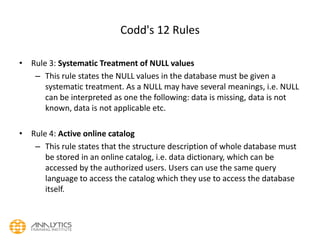
  • 35. Codd's 12 Rules • Rule 3: Systematic Treatment of NULL values – This rule states the NULL values in the database must be given a systematic treatment. As a NULL may have several meanings, i.e. NULL can be interpreted as one the following: data is missing, data is not known, data is not applicable etc. • Rule 4: Active online catalog – This rule states that the structure description of whole database must be stored in an online catalog, i.e. data dictionary, which can be accessed by the authorized users. Users can use the same query language to access the catalog which they use to access the database itself.
  • 36. Codd's 12 Rules • Rule 5: Comprehensive data sub-language rule – This rule states that a database must have a support for a language which has linear syntax which is capable of data definition, data manipulation and transaction management operations. Database can be accessed by means of this language only, either directly or by means of some application. If the database can be accessed or manipulated in some way without any help of this language, it is then a violation. • Rule 6: View updating rule – This rule states that all views of database, which can theoretically be updated, must also be updatable by the system.
  • 37. Codd's 12 Rules • Rule 7: High-level insert, update and delete rule – This rule states the database must employ support high-level insertion, updation and deletion. This must not be limited to a single row that is, it must also support union, intersection and minus operations to yield sets of data records. • Rule 8: Physical data independence – This rule states that the application should not have any concern about how the data is physically stored. Also, any change in its physical structure must not have any impact on application.
  • 38. Codd's 12 Rules • Rule 9: Logical data independence – This rule states that the logical data must be independent of its user’s view (application). Any change in logical data must not imply any change in the application using it. For example, if two tables are merged or one is split into two different tables, there should be no impact the change on user application. This is one of the most difficult rule to apply. • Rule 10: Integrity independence – This rule states that the database must be independent of the application using it. All its integrity constraints can be independently modified without the need of any change in the application. This rule makes database independent of the front-end application and its interface.
  • 39. Codd's 12 Rules • Rule 11: Distribution independence – This rule states that the end user must not be able to see that the data is distributed over various locations. User must also see that data is located at one site only. This rule has been proven as a foundation of distributed database systems. • Rule 12: Non-subversion rule – This rule states that if a system has an interface that provides access to low level records, this interface then must not be able to subvert the system and bypass security and integrity constraints.
  • 40. Constraints • Every relation has some conditions that must hold for it to be a valid relation. These conditions are called Relational Integrity Constraints. • There are three main integrity constraints. – Key Constraints – Domain constraints – Referential integrity constraints
  • 41. Constraints • KEY CONSTRAINTS: – There must be at least one minimal subset of attributes in the relation, which can identify a record uniquely. This minimal subset of attributes is called key for that relation. If there are more than one such minimal subsets, these are called candidate keys. • Key constraints forces that: – in a relation with a key attribute, no two tuples can have identical value for key attributes. – key attribute can not have NULL values. • Key constrains are also referred to as Entity Constraints.
  • 42. Constraints • DOMAIN CONSTRAINTS – Attributes have specific values in real-world scenario. – Every attribute is bound to have a specific range of values. – For example, age can only be positive integer and telephone number cannot be outside 0-9.
  • 43. Constraints • REFERENTIAL INTEGRITY CONSTRAINTS – This integrity constraints works on the concept of Foreign Key. A key attribute of a relation can be referred in other relation, where it is called foreign key. – Referential integrity constraint states that if a relation refers to an key attribute of a different or same relation, that key element must exists.
  • 44. Normalization • If a database design is not perfect it may contain anomalies, which are like a bad dream for database itself. Managing a database with anomalies is next to impossible. – Update anomalies: if data items are scattered and are not linked to each other properly, then there may be instances when we try to update one data item that has copies of it scattered at several places, few instances of it get updated properly while few are left with there old values. This leaves database in an inconsistent state. – Deletion anomalies: we tried to delete a record, but parts of it left undeleted because of unawareness, the data is also saved somewhere else. – Insert anomalies: we tried to insert data in a record that does not exist at all. • Normalization is a method to remove all these anomalies and bring database to consistent state and free from any kinds of anomalies.
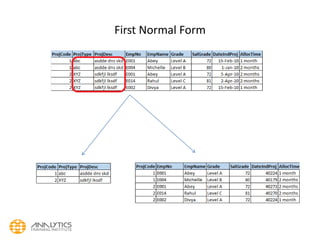
  • 45. Normalization • First Normal Form: – This is defined in the definition of relations (tables) itself. This rule defines that all the attributes in a relation must have atomic domains. Values in atomic domain are indivisible units. – all repeating group columns on a single primary key are split into a separate relationship leaving behind the primary key column in the other relation to form a composite primary key
  • 47. Normalization • Second Normal Form: • Before we learn about second normal form, we need to understand the following: – Prime attribute: an attribute, which is part of prime-key, is prime attribute. – Non-prime attribute: an attribute, which is not a part of prime-key, is said to be a non-prime attribute. • Second normal form says, that every non-prime attribute should be fully functionally dependent on prime key attribute. That is, if X → A holds, then there should not be any proper subset Y of X, for that Y → A also holds. • For those with compound (or composite) primary key, examine every non key column and ask whether it depends on whole of the compound key or just on some part of it. • Remove those that depend only on some part of the key to a new relation with that part as the primary key.
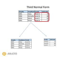
  • 49. Normalization • Third Normal Form: • For a relation to be in Third Normal Form, it must be in Second Normal form and the following must satisfy: • No non-prime attribute is transitively dependent on prime key attribute • For any non-trivial functional dependency, X → A, then either X is a superkey or, A is prime attribute. • Examine every non key column and question its relationship with other non key column. • In the previous example, CustName and CustAddr depends on CustNo, which depends on OrderNo • So CustName and CustAddr transitively (or indirectly) depend on OrderNo and hence should be separated as a new relation.
  • 55. SQL Overview • SQL is a programming language for Relational Databases • SQL comprises both data definition and data manipulation languages. • Using the data definition properties of SQL, one can design and modify database schema whereas data manipulation properties allows SQL to store and retrieve data from database.
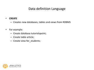
  • 56. Data definition Language • CREATE – Creates new databases, tables and views from RDBMS • For example: – Create database tutorialspoint; – Create table article; – Create view for_students;
  • 57. Data definition Language • DROP • Drop commands deletes views, tables and databases from RDBMS – Drop object_type object_name; – Drop database tutorialspoint; – Drop table article; – Drop view for_students;
  • 58. Data definition Language • ALTER • Modifies database schema. • Alter object_type, object_name parameters; • for example: – Alter table article add subject varchar; • This command adds an attribute in relation article with name subject of string type.
  • 59. Data Manipulation Language • SQL is equipped with data manipulation language. DML modifies the database instance by inserting, updating and deleting its data. • DML is responsible for all data modification in databases. SQL contains the following set of command in DML section: – SELECT/FROM/WHERE – INSERT INTO/VALUES – UPDATE/SET/WHERE – DELETE FROM/WHERE • These basic constructs allows database programmers and users to enter data and information into the database and retrieve efficiently using a number of filter options.
  • 60. Data Manipulation Language • SELECT/FROM/WHERE • SELECT • This is one of the fundamental query command of SQL. It is similar to projection operation of relational algebra. It selects the attributes based on the condition described by WHERE clause. • FROM • This clause takes a entity name as an argument from which attributes are to be selected/projected. In case more than one entity names are given this clause corresponds to cartesian product. • WHERE • This clause defines predicate or conditions which must match in order to qualify the attributes to be projected. • For example: Select author_name From book_author Where age > 50;This command will project names of author’s from book_author entity whose age is greater than 50.
  • 61. Data Manipulation Language • INSERT INTO/VALUES • This command is used for inserting values into rows of table (relation). • Syntax - • INSERT INTO table (column1 [, column2, column3 ... ]) VALUES (value1 [, value2, value3 ... ]) • INSERT INTO table VALUES (value1, [value2, ... ]) • For Example: • INSERT INTO tutorialspoint (Author, Subject) VALUES ("anonymous", "computers");
  • 62. Data Manipulation Language • UPDATE/SET/WHERE • This command is used for updating or modifying values of columns of table (relation). • Syntax is • UPDATE table_name SET column_name = value [, column_name = value ...] [WHERE condition] • For example: • UPDATE tutorialspoint SET Author="webmaster" WHERE Author="anonymous";
  • 63. Data Manipulation Language • DELETE/FROM/WHERE • This command is used for removing one or more rows from table (relation). • Syntax is • DELETE FROM table_name [WHERE condition]; • For example: • DELETE FROM tutorialspoints WHERE Author="unknown";