SlideShare a Scribd company logo
12
Most read
13
Most read
17
Most read
Stick Diagram
&
Lambda Based Design Rules
Presented by:
TAHSIN AL MAHI
Student ID: 140934
Year: 4 Term: I
ECE Discipline
Khulna University
Khulna
7/29/2018 ECE KU 1
7/29/2018 ECE KU 2
Presentation Outline
Top Down Hierarchy of System Design in VLSI
What is Stick Diagram
Stick Encodings
A CMOS inverter
Color Codes
Some Rules
What is Lambda Based Design Rule
Design Rules
7/29/2018 ECE KU 3
Top Down Hierarchy of System Design in VLSI
System Specifications
System Design
Subsystem Design
Logic Design
Logic Circuit Electronic Circuit
Stick Diagram
Mask Layout
Fabrication
Chip
7/29/2018 ECE KU 4
What is Stick Diagram?
o Stick diagram is a cartoon of a layout.
o Conveying layer information through the use of a color code or
monochrome encoding.
o Monochrome encodings are black and white lines.
D
S
G G
S
D
a b
Fig: (a) nMOS; (b) Stick Diagram of the nMOS
7/29/2018 ECE KU 5
Stick Encoding Layer
Diffusion Layer (n-type or p-type)
Polysilicon
Metal
Contact Cut (Diffusion layer with Metal)
Buried Contact (Diffusion layer with polysilicon)
Implant (Channel between drain and source)
Demarcation line (between n and p type)
VIA (Contact between metal 1 and metal 2)
Body to substrate connection
Stick Encodings
7/29/2018 ECE KU 6
A CMOS Inverter
D
S
G
S
D
G
a b
Fig: (a) CMOS inverter; (b) Stick diagram of the CMOS inverter
DDV
outVinV
GND
DDV
GND
inV outV
7/29/2018 ECE KU 7
Color Codes
Layer Layer Name
Metal 1
Polysilicon
n-type diffusion
p-type diffusion
Demarcation line
7/29/2018 ECE KU 8
Some Rules
Rule 1: When two or more ‘sticks’ of the same type cross or touch each
other that represents electrical contact.
Fig: Same type of sticks are crossing
7/29/2018 ECE KU 9
Some Rules…
Rule 2: When two or more ‘sticks’ of different type cross or touch each
other there is no electrical contact. If electrical contact is needed we have to
show the connection explicitly.
Fig: Electrical contact between two different sticks
7/29/2018 ECE KU 10
Some Rules…
Rule 3: When a poly crosses diffusion it represents a transistor.
Fig: Transistor made out by crossing over diffusion and polysilicon
7/29/2018 ECE KU 11
Some Rules…
Rule 4: In CMOS a demarcation line is drawn to separate the nMOS and
the pMOS.
Fig: Demarcation line separating nMOS and pMOS
7/29/2018 ECE KU 12
What is Lambda Based Design Rule
o Setting out mask dimensions along a size-independent way.
o Mead and Conway provided these rules.
o (Lambda) is a unit and can be of any value.
o According this rule line widths, separations and extensions are
expressed in terms of .
o Mask layout is designed according to Lambda Based Designed Rule.
o Nowadays, .


nm14
7/29/2018 ECE KU 13
Design Rules
Fig: Design Rules for wires (nMOS and CMOS)
3
2
2
2
2
1
2
n-diffusion p-diffusion
Minimum
width
Minimum separation
(where specified)
Polysilicon
7/29/2018 ECE KU 14
Design Rules…
Fig: Design Rules for wires (nMOS and CMOS)
3
Minimum
width
3
4
4
Minimum separation
(where specified)
4
Metal 2
Metal 1
3
7/29/2018 ECE KU 15
Design Rules…
Fig: Transistor Design Rules (nMOS and pMOS)
 22   22 
2
2
 66 
nMOS
(enhancement)
pMOS
(enhancement)
pMOS
(depletion)
7/29/2018 ECE KU 16
Design Rules…
2 Minimum
Implant for an nMOS
depletion mode
transistor to extend 2y
minimum beyond
channel in all
directions
2 Minimum
minimum
2
2 minimum
2
Fig: Transistor Design Rules (CMOS)
7/29/2018 ECE KU 17
Design Rules…
minimum3
2
minimum
Fig: Transistor Design Rules (Metal 1 to Polysilicon or to Diffusion)
7/29/2018 ECE KU 18
Design Rules…
Metal 2
Metal 1
2 minimum separation
(if other spacings allows)
Cut
 44  area of overlap with
 22  via at center
Fig: Transistor Design Rules (contact from metal 2 to metal 1 and thence to other layers)
7/29/2018 ECE KU 19
Reference
 Basic VLSI Design by Douglas A. Pucknell & Kamran Eshraghian
 Stick Diagrams, Maharishi Markandeshwar University, Haryana, India
7/29/2018 ECE KU 20
Any Questions?
7/29/2018 ECE KU 21

More Related Content

What's hot (20)

PPTX
Layout & Stick Diagram Design Rules
varun kumar
 
PPTX
Cmos fabrication
jigyashamaru
 
DOCX
Lambda design rule
Gowri Kishore
 
PPTX
BiCMOS Technology
Mithileysh Sathiyanarayanan
 
PPTX
MOSFET fabrication 12
HIMANSHU DIWAKAR
 
PPTX
Silicon on Insulator (SOI) Technology
Sudhanshu Janwadkar
 
PPTX
Stick Diagram
Kalyan Acharjya
 
PPTX
Second order effects
PRAVEEN KUMAR CHITLURI
 
PDF
CMOS Topic 5 -_cmos_inverter
Ikhwan_Fakrudin
 
PPTX
MOS transistor 13
HIMANSHU DIWAKAR
 
PPTX
Short channel effects
aditiagrawal97
 
PPTX
Low Power Design Approach in VLSI
Silicon Mentor
 
PPTX
Cmos fabrication process
Ananda Mohan
 
PPT
Cmos
Naveen Sihag
 
PPTX
CMOS
AWANISHKUMAR84
 
PDF
Analog Layout design
slpinjare
 
PPT
Pass Transistor Logic
Diwaker Pant
 
PPTX
Rc delay modelling in vlsi
Dr. Vishal Sharma
 
PDF
Low power vlsi design ppt
Anil Yadav
 
PPTX
Device isolation Techniques
Sudhanshu Janwadkar
 
Layout & Stick Diagram Design Rules
varun kumar
 
Cmos fabrication
jigyashamaru
 
Lambda design rule
Gowri Kishore
 
BiCMOS Technology
Mithileysh Sathiyanarayanan
 
MOSFET fabrication 12
HIMANSHU DIWAKAR
 
Silicon on Insulator (SOI) Technology
Sudhanshu Janwadkar
 
Stick Diagram
Kalyan Acharjya
 
Second order effects
PRAVEEN KUMAR CHITLURI
 
CMOS Topic 5 -_cmos_inverter
Ikhwan_Fakrudin
 
MOS transistor 13
HIMANSHU DIWAKAR
 
Short channel effects
aditiagrawal97
 
Low Power Design Approach in VLSI
Silicon Mentor
 
Cmos fabrication process
Ananda Mohan
 
Analog Layout design
slpinjare
 
Pass Transistor Logic
Diwaker Pant
 
Rc delay modelling in vlsi
Dr. Vishal Sharma
 
Low power vlsi design ppt
Anil Yadav
 
Device isolation Techniques
Sudhanshu Janwadkar
 

Similar to Stick Diagram and Lambda Based Design Rules (20)

DOCX
MOS and BiCMOS Circuit design Process
Dr.YNM
 
PDF
Stick Diagram presentation slide for VLSI.pdf
MoyeenurRahman2
 
PDF
VLSI-Module-3.pdf
KarthiPoorni
 
PDF
VLSI-Design2
AcademicICECE
 
PPTX
Layouts
Sudhanshu Janwadkar
 
PPTX
Stick Diagrams design and lamda dia.pptx
dangerzonebeware20
 
PPT
VLSI circuit design process
Vishal kakade
 
PPTX
Vlsi stick daigram (JCE)
Hrishikesh Kamat
 
PPTX
Stick diagram and layout diagram ppt.pptx
MuhammedAsimA
 
PPT
design-rules-for nmos and pmos stick diagrams.ppt
hodece9t
 
PDF
Design concepts in Microelectronics
Tallinn University of Technology
 
PDF
MOS LAYERS, MOS design and four basic layers
ReguMohanraj
 
PPTX
vlsi-unit-3-ppt.pptx
8885684828
 
PPT
vlsi lambda rules and mos and bicmos circuits
hodece9t
 
DOCX
CMOS VLSI PROJECT || CMOS 3-Bit Binary to Square of the given Input || MULTIP...
rameshreddybattini
 
PDF
vlsi-unit-2-ppt.pdf for electronics engineering
MohitKumar202076
 
PDF
edited_VLSI DESIGN U2-1.pdf
AcademicICECE
 
PPTX
Very Largescale integration ppt for ECE.
Niranjan Reddy
 
PDF
tutorial about dic_lec_04_layout1_v01.pdf
ducminhle1604
 
PPT
stick diagrams is a cartton of layout which helps in designing and synthesis ...
AbhinandanAbhi6
 
MOS and BiCMOS Circuit design Process
Dr.YNM
 
Stick Diagram presentation slide for VLSI.pdf
MoyeenurRahman2
 
VLSI-Module-3.pdf
KarthiPoorni
 
VLSI-Design2
AcademicICECE
 
Stick Diagrams design and lamda dia.pptx
dangerzonebeware20
 
VLSI circuit design process
Vishal kakade
 
Vlsi stick daigram (JCE)
Hrishikesh Kamat
 
Stick diagram and layout diagram ppt.pptx
MuhammedAsimA
 
design-rules-for nmos and pmos stick diagrams.ppt
hodece9t
 
Design concepts in Microelectronics
Tallinn University of Technology
 
MOS LAYERS, MOS design and four basic layers
ReguMohanraj
 
vlsi-unit-3-ppt.pptx
8885684828
 
vlsi lambda rules and mos and bicmos circuits
hodece9t
 
CMOS VLSI PROJECT || CMOS 3-Bit Binary to Square of the given Input || MULTIP...
rameshreddybattini
 
vlsi-unit-2-ppt.pdf for electronics engineering
MohitKumar202076
 
edited_VLSI DESIGN U2-1.pdf
AcademicICECE
 
Very Largescale integration ppt for ECE.
Niranjan Reddy
 
tutorial about dic_lec_04_layout1_v01.pdf
ducminhle1604
 
stick diagrams is a cartton of layout which helps in designing and synthesis ...
AbhinandanAbhi6
 
Ad

Recently uploaded (20)

PDF
Statistical Data Analysis Using SPSS Software
shrikrishna kesharwani
 
PDF
International Journal of Information Technology Convergence and services (IJI...
ijitcsjournal4
 
PDF
A presentation on the Urban Heat Island Effect
studyfor7hrs
 
PPTX
Introduction to Neural Networks and Perceptron Learning Algorithm.pptx
Kayalvizhi A
 
PDF
Introduction to Productivity and Quality
মোঃ ফুরকান উদ্দিন জুয়েল
 
PDF
PORTFOLIO Golam Kibria Khan — architect with a passion for thoughtful design...
MasumKhan59
 
PDF
6th International Conference on Machine Learning Techniques and Data Science ...
ijistjournal
 
PDF
Ethics and Trustworthy AI in Healthcare – Governing Sensitive Data, Profiling...
AlqualsaDIResearchGr
 
PPTX
Green Building & Energy Conservation ppt
Sagar Sarangi
 
PPTX
Structural Functiona theory this important for the theorist
cagumaydanny26
 
PPTX
MPMC_Module-2 xxxxxxxxxxxxxxxxxxxxx.pptx
ShivanshVaidya5
 
PPTX
artificial intelligence applications in Geomatics
NawrasShatnawi1
 
PPTX
265587293-NFPA 101 Life safety code-PPT-1.pptx
chandermwason
 
PPT
inherently safer design for engineering.ppt
DhavalShah616893
 
DOCX
8th International Conference on Electrical Engineering (ELEN 2025)
elelijjournal653
 
PPTX
site survey architecture student B.arch.
sri02032006
 
PDF
ARC--BUILDING-UTILITIES-2-PART-2 (1).pdf
IzzyBaniquedBusto
 
PPTX
Pharmaceuticals and fine chemicals.pptxx
jaypa242004
 
PPT
Oxygen Co2 Transport in the Lungs(Exchange og gases)
SUNDERLINSHIBUD
 
PDF
Book.pdf01_Intro.ppt algorithm for preperation stu used
archu26
 
Statistical Data Analysis Using SPSS Software
shrikrishna kesharwani
 
International Journal of Information Technology Convergence and services (IJI...
ijitcsjournal4
 
A presentation on the Urban Heat Island Effect
studyfor7hrs
 
Introduction to Neural Networks and Perceptron Learning Algorithm.pptx
Kayalvizhi A
 
Introduction to Productivity and Quality
মোঃ ফুরকান উদ্দিন জুয়েল
 
PORTFOLIO Golam Kibria Khan — architect with a passion for thoughtful design...
MasumKhan59
 
6th International Conference on Machine Learning Techniques and Data Science ...
ijistjournal
 
Ethics and Trustworthy AI in Healthcare – Governing Sensitive Data, Profiling...
AlqualsaDIResearchGr
 
Green Building & Energy Conservation ppt
Sagar Sarangi
 
Structural Functiona theory this important for the theorist
cagumaydanny26
 
MPMC_Module-2 xxxxxxxxxxxxxxxxxxxxx.pptx
ShivanshVaidya5
 
artificial intelligence applications in Geomatics
NawrasShatnawi1
 
265587293-NFPA 101 Life safety code-PPT-1.pptx
chandermwason
 
inherently safer design for engineering.ppt
DhavalShah616893
 
8th International Conference on Electrical Engineering (ELEN 2025)
elelijjournal653
 
site survey architecture student B.arch.
sri02032006
 
ARC--BUILDING-UTILITIES-2-PART-2 (1).pdf
IzzyBaniquedBusto
 
Pharmaceuticals and fine chemicals.pptxx
jaypa242004
 
Oxygen Co2 Transport in the Lungs(Exchange og gases)
SUNDERLINSHIBUD
 
Book.pdf01_Intro.ppt algorithm for preperation stu used
archu26
 
Ad

Stick Diagram and Lambda Based Design Rules

  • 1. Stick Diagram & Lambda Based Design Rules Presented by: TAHSIN AL MAHI Student ID: 140934 Year: 4 Term: I ECE Discipline Khulna University Khulna 7/29/2018 ECE KU 1
  • 2. 7/29/2018 ECE KU 2 Presentation Outline Top Down Hierarchy of System Design in VLSI What is Stick Diagram Stick Encodings A CMOS inverter Color Codes Some Rules What is Lambda Based Design Rule Design Rules
  • 3. 7/29/2018 ECE KU 3 Top Down Hierarchy of System Design in VLSI System Specifications System Design Subsystem Design Logic Design Logic Circuit Electronic Circuit Stick Diagram Mask Layout Fabrication Chip
  • 4. 7/29/2018 ECE KU 4 What is Stick Diagram? o Stick diagram is a cartoon of a layout. o Conveying layer information through the use of a color code or monochrome encoding. o Monochrome encodings are black and white lines. D S G G S D a b Fig: (a) nMOS; (b) Stick Diagram of the nMOS
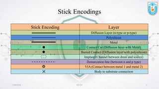
  • 5. 7/29/2018 ECE KU 5 Stick Encoding Layer Diffusion Layer (n-type or p-type) Polysilicon Metal Contact Cut (Diffusion layer with Metal) Buried Contact (Diffusion layer with polysilicon) Implant (Channel between drain and source) Demarcation line (between n and p type) VIA (Contact between metal 1 and metal 2) Body to substrate connection Stick Encodings
  • 6. 7/29/2018 ECE KU 6 A CMOS Inverter D S G S D G a b Fig: (a) CMOS inverter; (b) Stick diagram of the CMOS inverter DDV outVinV GND DDV GND inV outV
  • 7. 7/29/2018 ECE KU 7 Color Codes Layer Layer Name Metal 1 Polysilicon n-type diffusion p-type diffusion Demarcation line
  • 8. 7/29/2018 ECE KU 8 Some Rules Rule 1: When two or more ‘sticks’ of the same type cross or touch each other that represents electrical contact. Fig: Same type of sticks are crossing
  • 9. 7/29/2018 ECE KU 9 Some Rules… Rule 2: When two or more ‘sticks’ of different type cross or touch each other there is no electrical contact. If electrical contact is needed we have to show the connection explicitly. Fig: Electrical contact between two different sticks
  • 10. 7/29/2018 ECE KU 10 Some Rules… Rule 3: When a poly crosses diffusion it represents a transistor. Fig: Transistor made out by crossing over diffusion and polysilicon
  • 11. 7/29/2018 ECE KU 11 Some Rules… Rule 4: In CMOS a demarcation line is drawn to separate the nMOS and the pMOS. Fig: Demarcation line separating nMOS and pMOS
  • 12. 7/29/2018 ECE KU 12 What is Lambda Based Design Rule o Setting out mask dimensions along a size-independent way. o Mead and Conway provided these rules. o (Lambda) is a unit and can be of any value. o According this rule line widths, separations and extensions are expressed in terms of . o Mask layout is designed according to Lambda Based Designed Rule. o Nowadays, .   nm14
  • 13. 7/29/2018 ECE KU 13 Design Rules Fig: Design Rules for wires (nMOS and CMOS) 3 2 2 2 2 1 2 n-diffusion p-diffusion Minimum width Minimum separation (where specified) Polysilicon
  • 14. 7/29/2018 ECE KU 14 Design Rules… Fig: Design Rules for wires (nMOS and CMOS) 3 Minimum width 3 4 4 Minimum separation (where specified) 4 Metal 2 Metal 1 3
  • 15. 7/29/2018 ECE KU 15 Design Rules… Fig: Transistor Design Rules (nMOS and pMOS)  22   22  2 2  66  nMOS (enhancement) pMOS (enhancement) pMOS (depletion)
  • 16. 7/29/2018 ECE KU 16 Design Rules… 2 Minimum Implant for an nMOS depletion mode transistor to extend 2y minimum beyond channel in all directions 2 Minimum minimum 2 2 minimum 2 Fig: Transistor Design Rules (CMOS)
  • 17. 7/29/2018 ECE KU 17 Design Rules… minimum3 2 minimum Fig: Transistor Design Rules (Metal 1 to Polysilicon or to Diffusion)
  • 18. 7/29/2018 ECE KU 18 Design Rules… Metal 2 Metal 1 2 minimum separation (if other spacings allows) Cut  44  area of overlap with  22  via at center Fig: Transistor Design Rules (contact from metal 2 to metal 1 and thence to other layers)
  • 19. 7/29/2018 ECE KU 19 Reference  Basic VLSI Design by Douglas A. Pucknell & Kamran Eshraghian  Stick Diagrams, Maharishi Markandeshwar University, Haryana, India
  • 20. 7/29/2018 ECE KU 20 Any Questions?