SlideShare a Scribd company logo
1
CHAPTER 1
EMBEDDED SYSTEM
1.1 INTRODUCTION TO EMBEDDED SYSTEM
Embedded System is a special purpose computer. It helps in infusing artificial
intelligence into an electronic system.
 DEFINITION:
Embedded System is a combination of Hardware and Software to meet specific needs
in a given time frame.
E.g.: Daily life embedded systems are cell phones, printers, ATM etc.
Fig. 1.1 An Embedded System
Suppose you have a bare processor , its bare so you can not dare to ask it save any
result anywhere , thus you “added” a memory , let’s say “added” in a better term that
“you embedded a memory ” that is your RAM.
2
Now you want to forward this logic to real world , before adding some output pins
you need a register to bridge between RAM and output pins , this register do a
special function of forwarding logic 1 and 0 in a term of 5 and 0 volts , so that’s a
special function. So there you SFR and output PIN.
An embedded system is a system that has a software embedded into hardware, which
makes a system dedicated for an application or specific part of an application or
product or part of a larger system. It processes a fixed set of pre-programmed
instructions to control electromechanical equipment which may be a part of even
larger system (not a computer wid keyboard, display, etc.).
A general purpose definition of embedded system is that they are devices used to
control monitor or assist the operation of equipment, machinery or plant.
“Embedded” reflects the fact that they are an integral part of the system.
1.2 CHARACTERISTICS OF EMBEDDED SYSTEM
 Modern embedded systems are based on microcontrollers. A
microcontroller is a small, low-cost computer-on-a-chip which usually
includes:
1. A microprocessor (CPU).
2. A small amount of RAM.
3. Programmable ROM and/or flash memory.
4. Parallel and/or serial I/O.
5. Timers and signal generators.
6. Analog to Digital (A/D) and/or Digital to Analog (D/A) conversion.
1.3 Why embedded system?
 Take it as granted, that everything which runs on electric and does not have
motor, shall be a part of embedded.
 Robotics is a major part of embedded, which concern hoe to interface
machinery with our software to perform a certain task
 Though , definition of an embedded system says ‘A circuit which has been
programmed to perform a particular task’ , but it’s a human need to utilize a
3
gadget (electronics) as much as it could do, here we come with general
purpose system (a system which can perform many task).This part has
software and efficient coding in main concern.
 Embedded has booming future, this is predecessor of robotics, Al and various
human-machine interface.
4
CHAPTER 2
EMBEDDED C
2.1 INTRODUCTION
 Embedded c is a subset of c language which is compatible with certain
microcontrollers.
 Some features are added using header files like <avr/io.h>, <util/delay.h>.
 Scanf and printf are removed as the inputs are sanned from the sensors and
outputs are given to the ports.
 Control structures remain the same like if-statement, for loop, do while etc.
2.2 STRUCTURE OF A C PROGRAM FOR AN EMBEDDED
SYSTEM
//Headers
#include<avr/io.h>//header file for avr i/o
#include<util/delay.h>//header file for delay
//main program
{
Int main ()
While(1)
{
code….
}
Return (0);
}
5
2.3 STATEMENTS USED IN EMBEDDED C
2.3.1 If – statement
Syntax:
If(condition)
{
Statement……
}
Else
{
Statement……
}
Program for if statement
Int a=4;
Int b=5;
If(a>b)
Printf(“a is largest”);
Else
Printf(“b is largest”);
2.3.2 Do while loop
Syntax:
Initial counter
Do
{
statement…..
update statement
}
While (condition);
6
Program for do while
Int A=4;
Do
{
A++;
}
While(A>5);
2.3.3 For – statement
Syntax:
For(initial counter; test condition; update statement)
{
Statement….
Statement….
}
Program for for-statement
For(int i=0;i<5;i++)
Printf(“hello sir’14”);
7
CHAPTER 3
BASIC ELECTRONICS COMPONENTS
3.1 RESISTOR
A resistor is a two-terminal passive electronic component. It is that limits or
regulates the flow of electrical current, voltage and power dissipation in an electronic
circuit. Resistors can also be used to provide a specific voltage for an active device
such as transistor. Mainly resistor are classified according to their resistance values
and there power ratings. Resistances range from 10ohm to 56mohm (or more) and
power ratings from 1/8w to20
Units
The ohm (symbol: Ω). Commonly used multiples and submultiples in electrical and
electronic usage are the milliohm (1x10⁻³
), kilohm (1x10³
), and megaohm (1x10⁶
).
Color coding
We can measure the resistance of a resistor. This is done by color coding over the
resistor you can use multi-meter to measure resistance. As a beginner you should use
color coding. Usually we can see that 4-band code, 5-band code and 6-band code
registers are available but we mainly get resistors of 4- band code.
Fig. 3.1 Resistor color coding
8
3.3 Capacitor
A capacitor is used to store charge. Like resistors there is fixed as well as variable
capacitor also. But we mostly use fixed capacitor in robotics; variable capacitors are
mainly used in analog communication. These are capacitors with no polarity.
Ceramic and mica capacitors available are of no polarity, but electrolytic capacitors
are of polarity.
We can identify negative lead of electrolytic capacitor by checking the length of the
lead, one with less length s –ve. On the body of electrolytic capacitor –ve symbol is
shown. Be careful about electrolytic capacitor because inverting polarity can make
‘explosion’.
Every electrolytic has two factors- value of its capacitance and other maximum
voltagerating.
There are mainly two types of capacitors.
1. Electrolytic capacitor- they are used for low frequency, high capacity
applications and they are “polar” meaning that one leg must be connected to
negative and the other must be connected to positive supply. One of their use
is as low frequency filter in power supplies.
2. Ceramic capacitors- they are used in high frequency, low capacity
applications. One of their use in computers is for filtering high frequency
noise from the system.
C = Q / V
9
Fig. 3.2 Capacitors
3.4 POWER SUPPLY
Fig. 3.3 Power supply circuit diagram
Operating Voltages
● 2.7 - 5.5V (ATmega8L)
● 4.5 - 5.5V (ATmega8)
10
Power Consumption at 4 Mhz, 3V, 25°C
● Active: 3.6 mA
● Idle Mode: 1.0 mA
● Power-down Mode: 0.5 μA
3.4.1 BRIDGE RECTIFIERS
Bridge rectifier circuit consists of four diodes arranged in the form of a bridge as
shown in figure.
Operation:
During the positive half cycle of the input supply, the upper end A of the transformer
secondary becomes positive with respect to its lower point B. This makes Point1 of
bridge positive with respect to point2. The diode D1 & D2 become forward biased &
D3 & D4 become reverse biased. As a result a current starts flowing from point1,
through D1 the load & D2 to the negative end.
During negative half cycle, the point2 becomes positive with respect to point1.
DiodeD1 & D2 now become reverse biased. Thus a current flow from point 2 to point
1.
11
CHAPTER 4
MICROCONTROLLER
4.1 INTRODUCTION
The situation we find ourselves today in the field of microcontrollers has its beginnings
in the development of technology of integrated circuits. It enabled us to store hundreds
of thousands of transistors into one chip, which was a precondition for the manufacture
of microprocessors. The first computers were made by adding external peripherals,
such as memory, input/output lines, timers and other circuits, to it. Further increasing
of package density resulted in designing an integrated circuit which contained both
processor and peripherals. This is how the first chip containing a microcomputer later
known as the microcontroller was developed.
4.2 CHARACTERISTICS OF MICROCONTROLLERS
• Microcontrollers are important part of Embedded systems
• To understand Structure & working of Microcontrollers
• For designing good embedded system complete understanding of
microcontrollers required.
• Integrated chip that typically contains integrated CPU, programmable
memory (RAM ROM), parallel and/or I/O ports on a single Chip.
• System on a single Chip.
• Designed to execute a specific task to control a single system.
• Smaller & specified (design cost).
• Differs from Microprocessor.
• General -purpose chip.
• Used to design multipurpose computers or devices.
12
• Require multiple chips to handle various tasks.
• Timers and signal generators
• Analog to Digital (A/D) and/or Digital to Analog (D/A) conversion
4.3 DIFFERENCE BETWEEN MICROPROCESSOR AND
MICROCONTROLLER
MICROPROCESSOR MICROCONTROLLER
Microprocessor assimilates the function of a
central processing unit (CPU) on to a single
integrated circuit (IC).
Microcontroller can be considered as a
small computer which has a processor and
some other components in order to make it
a computer.
Microprocessors are mainly used in designing
general purpose systems from small to large
and complex systems like super computers.
Microcontrollers are used in automatically
controlled devices.
Microprocessors are basic components of
personal computers.
Microcontrollers are generally used in
embedded systems
Computational capacity of microprocessor is
very high. Hence can perform complex tasks.
Less computational capacity when
compared to microprocessors. Usually
used for simpler tasks.
13
A microprocessor based system can perform
numerous tasks.
A microcontroller based system can
perform single or very few tasks.
Microprocessors have integrated Math
Coprocessor. Complex mathematical
calculations which involve floating point can
be performed with great ease.
Microcontrollers do not have math
coprocessors. They use software to
perform floating point calculations which
slows down the device.
The main task of microprocessor is to perform
the instruction cycle repeatedly. This includes
fetch, decode and execute.
In addition to performing the tasks of
fetch, decode and execute, a
microcontroller also controls its
environment based on the output of the
instruction cycle.
In order to build or design a system
(computer), a microprocessor has to be
connected externally to some other
components like Memory (RAM and ROM)
and Input / Output ports.
The IC of a microcontroller has memory
(both RAM and ROM) integrated on it
along with some other components like I /
O devices and timers.
14
The overall cost of a system built using a
microprocessor is high. This is because of the
requirement of external components.
Cost of a system built using a
microcontroller is less as all the
components are readily available.
Generally power consumption and dissipation
is high because of the external devices. Hence
it requires external cooling system.
Power consumption is less.
Instruction throughput is given higher priority
than interrupt latency.
In contrast, microcontrollers are designed
to optimize interrupt latency.
15
CHAPTER 5
AVR MICROCONTROLLER
5.1 INTRODUCTION
Fig. 5.1 AVR
AVR stands for Advanced Virtual RISC. The AVR is a modified Harvard
architecture 8-bit RISC single chip microcontroller which was developed
by Atmel in 1996. The AVR was one of the first microcontroller families to use on-
chip flash memory for program storage, as opposed to one-time programmable
ROM, EPROM, or EEPROM used by other microcontrollers at the time.
5.2 CLASSIFICATION OF AVR
AVRs are generally classified into following:
 Tiny AVR — the A tiny series
 0.5–16 kB program memory
 6–32-pin package
 Limited peripheral set
16
 Mega AVR — the A mega series
 4–512 KB program memory
 28–100-pin package
 Extended instruction set (multiply instructions and instructions for handling
larger program memories)
 Extensive peripheral set
 XMEGA — the A xmega series
 16–384 KB program memory
 44–64–100-pin package (A4, A3, A1)
 Extended performance features, such as DMA, "Event System", and
cryptography support.
 Extensive peripheral set with ADCs.
Mostly instruction Execute in Single clock cycle. Which makes it faster among 8 bit
microcontrollers.
AVR was designed for efficient execution of compiled C code.
5.3ARCHITECTURE OF AVR
The AVR is a Harvard architecture CPU.
Harvard Architecture
• Computer architectures that used physically separate storage and signal
pathways for their instructions and data.
• CPU can read both an instruction and data from memory at the same time
that makes it faster.
Von Neumann architecture
CPU can Read an instruction or data from/to the memory.
Read, Write can`t occur at the same time due to same memory and signal pathway
for data and instructions.
17
Fig. 5.2 Architecture of AVR
 Connection of components with CPU within a Microcontroller is called a
BUS. There are three types of bus:
1. Address Bus: It specifies the address.
2. Data Bus: It reads and writes on a specific address.
3. Control Bus: it controls the actions by sending and receiving messages, thus
it is bidirectional.
Key of microcontroller:
1. Register: it is a temporary storage and is a part of RAM. There are two types
of registers- General Purpose Registers (GPR) and Specific Function Registers
(SFR).
GENERAL purpose
 32 general purpose registers having storage capacity of 8 bit
 Named as R0,R1,R2 to R31.
 Register 0 to 15 & 16 to 31 are different.
 Can store both Data & Addresses.
18
SPECIAL purpose: Three registers
 Program counter
 Stack Pointer
 Status Register
2. Program Counter: it contains the address of next instruction to be executed
by the CPU. It is also a register.
3. Accumulator: it is an intermediate register on which all Arithmetic and
Logical operations are performed.
4. Clock Signals: these are digital signals which synchronize the action of a
microcontroller.
5. Flash ROM: it is where the program code is stored. It is a fast erasing
technology and erases all the contents at a time.
6. Interrupt: The interrupts refer to a notification, communicated to the
controller, by a hardware device or software, on receipt of which controller
momentarily stops and responds to the interrupt.
7. Stack: stack is used for the execution of the program. Whenever an interrupt
occurs or a subroutine is called, the previous section of program is pushed
onto the stack. After execution of the interrupt or the subroutine the execution
is resumed from that part which was getting executed previously.
5.4 ATMEGA8
Fig. 5.3 Atmega8
19
5.4.1 ATmega8 - RISC Architecture
● 130 Instructions – Most Single-clock Cycle Execution
● 32 x 8 General Purpose Working Registers
● 64 x 8 Special Function Registers (I/O Registers)
● Up to 16 MIPS Throughput at 16 MHz
● On-chip 2-cycle Multiplier
Nonvolatile Program and Data Memories
● 8K Bytes of In-System Self-Programmable Flash
10,000 Write/Erase Cycles
● Optional Boot Code Section with Independent Lock Bits
● 512 Bytes EEPROM (100,000 Write/Erase Cycles)
● 1K Byte Internal SRAM
● Programming Lock for Software Security
Peripheral Features
● Two 8-bit Timer/Counters
● One 16-bit Timer/Counter with Capture Mode
● Real Time Counter with Separate Oscillator
● Three PWM Channels
● 6-channel ADC with 10 resp 8 Bit resolution (TQFP: 8 channels)
● Two-wire Serial Interface (TWI)
● Programmable Serial USART
● Master/Slave SPI Serial Interface
● Programmable Watchdog Timer with On-chip Oscillator
● On-chip Analog Comparator
Special Microcontroller Features
● Programmable Brown-out Detection
● Internal Calibrated RC Oscillator
● External and Internal Interrupt Sources
20
● Five Sleep Modes
I/O and Packages
● 23 Programmable I/O Lines
● 28-lead PDIP, 32-lead TQFP, and 32-pad MLF
Operating Voltages
● 2.7 - 5.5V (ATmega8L)
● 4.5 - 5.5V (ATmega8)
Speed Grades
● 0 - 8 MHz (ATmega8L)
● 0 - 16 MHz (ATmega8)
Power Consumption at 4 Mhz, 3V, 25°C
● Active: 3.6 mA
● Idle Mode: 1.0 mA
● Power-down Mode: 0.5 μA
21
5.4.2 Pin and Port Overview:
Fig. 5.4 PDIP view of atmega8
22
Fig. 5.5 TQFP top view of atmega8
GND: Ground (0V)
VCC: Digital Supply Voltage (2,7 – 5,5V)
AVCC: Analog Supply Voltage
connect to low-pass filtered VCC
AREF: Analog Reference Voltage, usually AVCC
/Reset: Low level on this pin will generate a reset
Port B, Port C, Port D:
General Purpose 8 Bit bidirectional I/O - Ports,
Optional internal pull up-resistors when configured as input
Output source capability: 20mA
23
Special Functions of the Ports available as configured using the SFRs:
Port D: Uart, external Interrupts, Analog Comparator
Port B: External Oscillator/Crystal, SPI
Port C: A/D converters, TWI
5.4.3 ATMEGA 8 CORE ARCHITECTURE
Fig. 5.6 Core Architecture of atmega8
● Seperate Instruction and
Data Memories (Harvard)
● all 32 General Purpose
Registers connected to
ALU
24
● I/O Modules connected to
Data Bus and accessible via
Special Function Registers
Fig. 5.7 Harvard Architecture of atmega8
● Separate storage and signal pathways for
instructions and data.
● History: Harvard Mark I
relay-based computer
● word width, timing, and implementation
technology of instruction and data memories
can differ.
● Contrast: ‘Von Neumann’ - architecture:
Instructions and data use the same signal
pathways and memory.
25
Ability to fetch the next instruction at the
same time it completes the current
instruction.
● Speed is gained at the expense of more
complex electrical circuitry.
5.4.4 Memory organization:
Fig. 5.8 Memory Organization of Atmega8
26
● Program Flash Memor y:
On-chip, in system programmable
8 Kbytes, organized in 4K 16 bit words
Program Counter (PC) = 12 bits
Accessible via special instructions: LPM, SPM
Boot Loader support: Boot Flash Section,
SPM can be executed only from Boot Flash
● EEPROM - Memory:
512 Bytes, single Bytes can be read and written
Special EEPROM read and write procedure using SFRs:
EEPROM Address Register, EEPROM Data Register,
EEPROM Control Register
C – Library Functions available
Precautions to prevent EEPROM memory corruption:
● No flash memory or interrupt operations
● Stable power supply
27
CHAPTER 6
PROGRAMS
6.1 7-segment display
Fig. 6.1 7-Segment Display
A seven-segment display (SSD), or seven-segment indicator, is a form of
electronic display device for displaying decimal numerals that is an
alternative to the more complex dot matrix displays.
Seven-segment displays are widely used in digital clocks, electronic meters,
basic calculators, and other electronic devices that display numerical
information.
6.1.1 Introduction
The 7 segment display can also be used for displaying numbers. Each of the segments
of the display is connected to a pin on the 8051. In order to light up a segment on the
pin must be set to 0V. To turn a segment off the corresponding pin must be set to 5V.
28
This is simply done by setting the pins on the 8051 to '1' or '0'. LED displays are
Power-hungry (10mA per LED) and Pin-hungry (8 pins per 7-seg display). But they
are cheaper than LCD display.
7-SEG Display is available in two types -1. Common anode & 2. Common
cathode, but command anode display is most suitable for interfacing with 8051 since
8051 port pins can sink current better than sourcing it.
Fig. 6.2 Types of 7-Segment Display
6.1.2 Creating Digit Pattern
In Common Anode display, the common Anode pin is tied to 5v .The cathode pins are
connected to port 1 through 330 Ohm resistance (current limiting). For displaying
Digit say 7 we need to light segments -a ,b, c. in Common anode display , to do so we
have to provide Logic -0 (0 v) at cathode of these segments. So need to clear pins-
P1.0 ,P1.1,P1.2. That is 1 1 1 1 1 0 0 0 -->F8h.
Digit Seg. h Seg. g Seg. f Seg. e Seg. d Seg. c Seg. b Seg. a HEX
0 1 1 0 0 0 0 0 0 C0
1 1 1 1 1 1 0 0 1 F9
2 1 0 1 0 0 1 0 0 A4
3 1 0 1 1 0 0 0 0 B0
4 1 0 0 1 1 0 0 1 99
Table 6.1: Hex Code for Displaying Various Digits
29
6.1.3 Multi 7 Segment interfacing
Fig. 6.3 Interfacing Multi 7-Segment Display
Since we can Enable only one 7-seg display at a time ,we need to scan these
display at fast rate .the data lines are common for all the 4 segments The
scanning frequency should be high enough to be flicker-free. At least 30HZ
.Therefore – time one digit is ON is 1/30 seconds
30
6.1.4 PROGRAM FOR INTERFACING OF 7 SEGMENT
DIPLAY WITH AVR MICROCONTROLLER
#include <avr/io.h>
#include <util/delay.h>
int main(void)
{
DDRA = 0xFF; // Configure port B as output
while(1)
{
//TODO:: application code
PORTA = 0b00110000; // Display Number 1
_delay_ms(1000); // Wait for 1s
PORTA = 0b01011011; // Display Number 2
_delay_ms(1000); // Wait for 1s
PORTA = 0b01001111; // Display Number 3
_delay_ms(1000); // Wait for 1s
PORTA = 0b01100110; // Display Number 4
_delay_ms(1000); // Wait for 1s
PORTA = 0b01110111; // Display Letter A
_delay_ms(1000); // Wait for 1s
PORTA = 0b00111001; // Display Letter C
_delay_ms(1000); // Wait for 1s
PORTA = 0b01111001; // Display Letter E
_delay_ms(1000); // Wait for 1s
PORTA = 0b01110001; // Display Letter F
_delay_ms(1000); // Wait for 1s
}
return 0;}
31
Fig. 6.4 Simulated Circuit
6.2LCD
6.2.1 Introduction
A liquid-crystal display (LCD) is a flat panel display, electronic visual display, or video
display that uses the light modulating properties of Liquid crystals. Liquid crystals do not
emit light directly
A liquid-crystal display (LCD) is a flat panel display, electronic visual display, or video
display that uses the light modulating properties of Liquid crystals. Liquid crystals do not
emit light directly
32
Fig. 6.5 LCD
A liquid crystal display, is a thin, flat panel used for electronically displaying
information such as text, images, and moving pictures. Its uses include monitors for
computers, televisions, instrument panels, and other devices ranging from aircraft
cockpit displays, to every-day consumer devices such as video players, gaming
devices, clocks, watches, calculators, and telephones. Among its major features are
its lightweight construction, its portability, and its ability to be produced in much
larger screen sizes than are practical for the construction of cathode ray tube (CRT)
display technology. Its low electrical power consumption enables it to be used in
battery-powered electronic equipment. It is an electronically-modulated optical
device made up of any number of pixels filled with liquid crystals and arrayed in
front of a light source (backlight) or reflector to produce images in color or
monochrome.
33
6.2.2 Program of 16x2 LCD interfacing with AVR
microcontroller atmega8
#include <avr/io.h>
void delay(unsigned char);
//Main Code
int main()
{
DDRB=0xff; //set PORTB as out put
DDRD=0b01110000; //Set PD.4,5 and 6 as Output
/*
RS=PD5
R/W=PD6
E=PD4 */
//Give Inital Delay for LCD to startup as LCD is a slower Device
delay(2);
init_lcd();
while(1)
{
lcd_cmd(0x80); //Goto Line-1,first position
lcd_send_string("WELCOME TO! ");
lcd_cmd(0xC0); //Goto Line-2, first position
lcd_send_string("EGLOB :) ");
lcd_cmd(0x01); //Clear the lcd
delay(1);
34
}
}
//LCD function
/*------------------------------------------------------------------------------------------------------------*/
//Function for sending commands to LCD
void lcd_cmd(unsigned char command)
{
//Put command on the Data Bus
PORTB = command;
//Enable LCD for command writing
PORTD = 0b00010000;
//Allow delay for LCD to read the databus
delay(1);
//Disable LCD again
PORTD = 0b00000000;
//Allow some more delay
delay(1);
}
//Function for sending Data to LCD
void lcd_data(unsigned char data)
{
//Put data on Data Bus
PORTB= data;
//Set R/S (Regiter Select) to High, and Enable to High
PORTD = 0b00110000;
//Allow for delay
35
delay(1);
//Disable LCD again
PORTD = 0b00100000;
//Allow for some more delay
delay(1);
}
//Function to send String to LCD
void lcd_send_string(char* string)
{
while(*string)
{
//Send value of pointer as data to LCD
lcd_data(*string);
//Increment string pointer
string++;
}
}
//Function to Initilise LCD
void init_lcd()
{
//Setup both lines of LCD
lcd_cmd(0x38);
//Set Cursor off - Enable LCD
lcd_cmd(0x0E);
//Clear Screen
lcd_cmd(0x01);
//Goto first position
lcd_cmd(0x80);
}
/*----------------------------------------------------------------------------------------------------------*/
//Delay function
36
void delay(unsigned char dtime)
{
int i,j;
for(i=0;i<=dtime;i++)
{
for(j=0;j<5000;j++);
}}
//You can use your own delay functions and replace this delay function with your code
/*-----------------------------------------------------------------------------------------------------------*/
Fig. 6.6 Simulated Circuit

More Related Content

What's hot (20)

PPTX
embedded system and AVR
Urvashi Khandelwal
 
PPTX
Embedded Systems - Training ppt
Nishant Kayal
 
DOC
Report file on Embedded systems
Sukhendra Chaudhary
 
DOCX
Training report on embedded sys_AVR
Galgotias College of Engg. & Tech.
 
PDF
Embedded Systems and IoT
Dr. Shivananda Koteshwar
 
PPTX
ppt on embedded system
manish katara
 
PDF
IoT Based Smart Energy Meter
ijtsrd
 
PDF
IR Based Home Automation
Sujit Nayak
 
PPTX
Raspberry Pi Using Python
Seggy Segaran
 
PDF
Unit VI CPLD-FPGA Architecture
Principal,Guru Nanak Institute of Technology, Nagpur
 
DOCX
Project Report on Embedded Systems
Suhani Singh
 
PPT
Embedded System Basics
Dr M Muruganandam Masilamani
 
PPSX
Spartan-II FPGA (xc2s30)
Dr. A. B. Shinde
 
PDF
Traffic light controller with verilog
Chetan Dabral
 
PPTX
Introduction to AVR Microcontroller
Mahmoud Sadat
 
PPTX
Wi-Fi Esp8266 nodemcu
creatjet3d labs
 
PPTX
Password based door locking system
Arjun Singh
 
PPTX
IoT Based Home Automation System Presantation
Farhan Ahmed Rahee
 
PDF
Embedded Systems Training Report
Akhil Garg
 
PDF
Internship Report on IOT & Robotics
Aman Jaiswal
 
embedded system and AVR
Urvashi Khandelwal
 
Embedded Systems - Training ppt
Nishant Kayal
 
Report file on Embedded systems
Sukhendra Chaudhary
 
Training report on embedded sys_AVR
Galgotias College of Engg. & Tech.
 
Embedded Systems and IoT
Dr. Shivananda Koteshwar
 
ppt on embedded system
manish katara
 
IoT Based Smart Energy Meter
ijtsrd
 
IR Based Home Automation
Sujit Nayak
 
Raspberry Pi Using Python
Seggy Segaran
 
Project Report on Embedded Systems
Suhani Singh
 
Embedded System Basics
Dr M Muruganandam Masilamani
 
Spartan-II FPGA (xc2s30)
Dr. A. B. Shinde
 
Traffic light controller with verilog
Chetan Dabral
 
Introduction to AVR Microcontroller
Mahmoud Sadat
 
Wi-Fi Esp8266 nodemcu
creatjet3d labs
 
Password based door locking system
Arjun Singh
 
IoT Based Home Automation System Presantation
Farhan Ahmed Rahee
 
Embedded Systems Training Report
Akhil Garg
 
Internship Report on IOT & Robotics
Aman Jaiswal
 

Similar to training report on embedded system and AVR (20)

DOCX
report on embedded system
seema kumawat
 
PPTX
INDUSTRIAL TRAINING REPORT EMBEDDED SYSTEM.pptx
MeghdeepSingh
 
PDF
E044081720
IJERA Editor
 
PPTX
Embedded system 8051 Microcontroller
ankitsharmaj
 
DOC
Embedded two mark question
JCT COLLEGE OF ENGINEERING AND TECHNOLOGY
 
PDF
Embedded Patient Monitoring System
ijesajournal
 
PPT
Gsm based smart card information for lost atm cards
Somanchi Aditya
 
DOCX
Density based traffic light controlling (2)
hardik1240
 
PPTX
Embedded systems
Shivashankar Sawalgi
 
DOCX
Project Report On Micro-controller Embedded System
Rkrishna Mishra
 
PPTX
Embedded systems presentation
Surender Singh
 
DOCX
Gesture control robot using accelerometer documentation
Rajendra Prasad
 
DOC
Project
ATUL KUJUR
 
DOCX
Industrial monitoring and control system using android application
Avinash Vemula
 
DOCX
Arduino PAPER ABOUT INTRODUCTION
NAGASAI547
 
PPTX
E-m--be-dde-d -sy-s-te---m_Day_1_ES.pptx
hppatidarmds28
 
PDF
Minor Project Report on - short range personal 'RADAR'.
Sarvesh Kushwaha
 
PDF
Introduction to Microcontrollers
SaravananVijayakumar4
 
DOC
Home automation
Moorthy kvn
 
PPT
Ppt embedded
karan bansal
 
report on embedded system
seema kumawat
 
INDUSTRIAL TRAINING REPORT EMBEDDED SYSTEM.pptx
MeghdeepSingh
 
E044081720
IJERA Editor
 
Embedded system 8051 Microcontroller
ankitsharmaj
 
Embedded two mark question
JCT COLLEGE OF ENGINEERING AND TECHNOLOGY
 
Embedded Patient Monitoring System
ijesajournal
 
Gsm based smart card information for lost atm cards
Somanchi Aditya
 
Density based traffic light controlling (2)
hardik1240
 
Embedded systems
Shivashankar Sawalgi
 
Project Report On Micro-controller Embedded System
Rkrishna Mishra
 
Embedded systems presentation
Surender Singh
 
Gesture control robot using accelerometer documentation
Rajendra Prasad
 
Project
ATUL KUJUR
 
Industrial monitoring and control system using android application
Avinash Vemula
 
Arduino PAPER ABOUT INTRODUCTION
NAGASAI547
 
E-m--be-dde-d -sy-s-te---m_Day_1_ES.pptx
hppatidarmds28
 
Minor Project Report on - short range personal 'RADAR'.
Sarvesh Kushwaha
 
Introduction to Microcontrollers
SaravananVijayakumar4
 
Home automation
Moorthy kvn
 
Ppt embedded
karan bansal
 
Ad

More from Urvashi Khandelwal (6)

PPTX
LEACH Cluster-based Routing Protocol for Wireless Sensor Networks
Urvashi Khandelwal
 
PPTX
Ppt on DMRC
Urvashi Khandelwal
 
DOCX
Report on Dmrc rolling stock
Urvashi Khandelwal
 
PPTX
ppt on inveters
Urvashi Khandelwal
 
DOCX
Report on inverters
Urvashi Khandelwal
 
PPTX
presentation on rotor balancing
Urvashi Khandelwal
 
LEACH Cluster-based Routing Protocol for Wireless Sensor Networks
Urvashi Khandelwal
 
Ppt on DMRC
Urvashi Khandelwal
 
Report on Dmrc rolling stock
Urvashi Khandelwal
 
ppt on inveters
Urvashi Khandelwal
 
Report on inverters
Urvashi Khandelwal
 
presentation on rotor balancing
Urvashi Khandelwal
 
Ad

Recently uploaded (20)

PPTX
Mechanical Design of shell and tube heat exchangers as per ASME Sec VIII Divi...
shahveer210504
 
PPTX
Knowledge Representation : Semantic Networks
Amity University, Patna
 
PDF
Data structures notes for unit 2 in computer science.pdf
sshubhamsingh265
 
PDF
Reasons for the succes of MENARD PRESSUREMETER.pdf
majdiamz
 
PPTX
美国电子版毕业证南卡罗莱纳大学上州分校水印成绩单USC学费发票定做学位证书编号怎么查
Taqyea
 
PDF
Design Thinking basics for Engineers.pdf
CMR University
 
PDF
3rd International Conference on Machine Learning and IoT (MLIoT 2025)
ClaraZara1
 
PPTX
MODULE 04 - CLOUD COMPUTING AND SECURITY.pptx
Alvas Institute of Engineering and technology, Moodabidri
 
PDF
SERVERLESS PERSONAL TO-DO LIST APPLICATION
anushaashraf20
 
PDF
methodology-driven-mbse-murphy-july-hsv-huntsville6680038572db67488e78ff00003...
henriqueltorres1
 
PPTX
Distribution reservoir and service storage pptx
dhanashree78
 
PPTX
OCS353 DATA SCIENCE FUNDAMENTALS- Unit 1 Introduction to Data Science
A R SIVANESH M.E., (Ph.D)
 
PPTX
GitOps_Without_K8s_Training_detailed git repository
DanialHabibi2
 
PPTX
澳洲电子毕业证澳大利亚圣母大学水印成绩单UNDA学生证网上可查学历
Taqyea
 
PPTX
Water Resources Engineering (CVE 728)--Slide 4.pptx
mohammedado3
 
PDF
Halide Perovskites’ Multifunctional Properties: Coordination Engineering, Coo...
TaameBerhe2
 
PDF
Pressure Measurement training for engineers and Technicians
AIESOLUTIONS
 
PPT
Footbinding.pptmnmkjkjkknmnnjkkkkkkkkkkkkkk
mamadoundiaye42742
 
PDF
MODULE-5 notes [BCG402-CG&V] PART-B.pdf
Alvas Institute of Engineering and technology, Moodabidri
 
PPTX
Final Major project a b c d e f g h i j k l m
bharathpsnab
 
Mechanical Design of shell and tube heat exchangers as per ASME Sec VIII Divi...
shahveer210504
 
Knowledge Representation : Semantic Networks
Amity University, Patna
 
Data structures notes for unit 2 in computer science.pdf
sshubhamsingh265
 
Reasons for the succes of MENARD PRESSUREMETER.pdf
majdiamz
 
美国电子版毕业证南卡罗莱纳大学上州分校水印成绩单USC学费发票定做学位证书编号怎么查
Taqyea
 
Design Thinking basics for Engineers.pdf
CMR University
 
3rd International Conference on Machine Learning and IoT (MLIoT 2025)
ClaraZara1
 
MODULE 04 - CLOUD COMPUTING AND SECURITY.pptx
Alvas Institute of Engineering and technology, Moodabidri
 
SERVERLESS PERSONAL TO-DO LIST APPLICATION
anushaashraf20
 
methodology-driven-mbse-murphy-july-hsv-huntsville6680038572db67488e78ff00003...
henriqueltorres1
 
Distribution reservoir and service storage pptx
dhanashree78
 
OCS353 DATA SCIENCE FUNDAMENTALS- Unit 1 Introduction to Data Science
A R SIVANESH M.E., (Ph.D)
 
GitOps_Without_K8s_Training_detailed git repository
DanialHabibi2
 
澳洲电子毕业证澳大利亚圣母大学水印成绩单UNDA学生证网上可查学历
Taqyea
 
Water Resources Engineering (CVE 728)--Slide 4.pptx
mohammedado3
 
Halide Perovskites’ Multifunctional Properties: Coordination Engineering, Coo...
TaameBerhe2
 
Pressure Measurement training for engineers and Technicians
AIESOLUTIONS
 
Footbinding.pptmnmkjkjkknmnnjkkkkkkkkkkkkkk
mamadoundiaye42742
 
MODULE-5 notes [BCG402-CG&V] PART-B.pdf
Alvas Institute of Engineering and technology, Moodabidri
 
Final Major project a b c d e f g h i j k l m
bharathpsnab
 

training report on embedded system and AVR

  • 1. 1 CHAPTER 1 EMBEDDED SYSTEM 1.1 INTRODUCTION TO EMBEDDED SYSTEM Embedded System is a special purpose computer. It helps in infusing artificial intelligence into an electronic system.  DEFINITION: Embedded System is a combination of Hardware and Software to meet specific needs in a given time frame. E.g.: Daily life embedded systems are cell phones, printers, ATM etc. Fig. 1.1 An Embedded System Suppose you have a bare processor , its bare so you can not dare to ask it save any result anywhere , thus you “added” a memory , let’s say “added” in a better term that “you embedded a memory ” that is your RAM.
  • 2. 2 Now you want to forward this logic to real world , before adding some output pins you need a register to bridge between RAM and output pins , this register do a special function of forwarding logic 1 and 0 in a term of 5 and 0 volts , so that’s a special function. So there you SFR and output PIN. An embedded system is a system that has a software embedded into hardware, which makes a system dedicated for an application or specific part of an application or product or part of a larger system. It processes a fixed set of pre-programmed instructions to control electromechanical equipment which may be a part of even larger system (not a computer wid keyboard, display, etc.). A general purpose definition of embedded system is that they are devices used to control monitor or assist the operation of equipment, machinery or plant. “Embedded” reflects the fact that they are an integral part of the system. 1.2 CHARACTERISTICS OF EMBEDDED SYSTEM  Modern embedded systems are based on microcontrollers. A microcontroller is a small, low-cost computer-on-a-chip which usually includes: 1. A microprocessor (CPU). 2. A small amount of RAM. 3. Programmable ROM and/or flash memory. 4. Parallel and/or serial I/O. 5. Timers and signal generators. 6. Analog to Digital (A/D) and/or Digital to Analog (D/A) conversion. 1.3 Why embedded system?  Take it as granted, that everything which runs on electric and does not have motor, shall be a part of embedded.  Robotics is a major part of embedded, which concern hoe to interface machinery with our software to perform a certain task  Though , definition of an embedded system says ‘A circuit which has been programmed to perform a particular task’ , but it’s a human need to utilize a
  • 3. 3 gadget (electronics) as much as it could do, here we come with general purpose system (a system which can perform many task).This part has software and efficient coding in main concern.  Embedded has booming future, this is predecessor of robotics, Al and various human-machine interface.
  • 4. 4 CHAPTER 2 EMBEDDED C 2.1 INTRODUCTION  Embedded c is a subset of c language which is compatible with certain microcontrollers.  Some features are added using header files like <avr/io.h>, <util/delay.h>.  Scanf and printf are removed as the inputs are sanned from the sensors and outputs are given to the ports.  Control structures remain the same like if-statement, for loop, do while etc. 2.2 STRUCTURE OF A C PROGRAM FOR AN EMBEDDED SYSTEM //Headers #include<avr/io.h>//header file for avr i/o #include<util/delay.h>//header file for delay //main program { Int main () While(1) { code…. } Return (0); }
  • 5. 5 2.3 STATEMENTS USED IN EMBEDDED C 2.3.1 If – statement Syntax: If(condition) { Statement…… } Else { Statement…… } Program for if statement Int a=4; Int b=5; If(a>b) Printf(“a is largest”); Else Printf(“b is largest”); 2.3.2 Do while loop Syntax: Initial counter Do { statement….. update statement } While (condition);
  • 6. 6 Program for do while Int A=4; Do { A++; } While(A>5); 2.3.3 For – statement Syntax: For(initial counter; test condition; update statement) { Statement…. Statement…. } Program for for-statement For(int i=0;i<5;i++) Printf(“hello sir’14”);
  • 7. 7 CHAPTER 3 BASIC ELECTRONICS COMPONENTS 3.1 RESISTOR A resistor is a two-terminal passive electronic component. It is that limits or regulates the flow of electrical current, voltage and power dissipation in an electronic circuit. Resistors can also be used to provide a specific voltage for an active device such as transistor. Mainly resistor are classified according to their resistance values and there power ratings. Resistances range from 10ohm to 56mohm (or more) and power ratings from 1/8w to20 Units The ohm (symbol: Ω). Commonly used multiples and submultiples in electrical and electronic usage are the milliohm (1x10⁻³ ), kilohm (1x10³ ), and megaohm (1x10⁶ ). Color coding We can measure the resistance of a resistor. This is done by color coding over the resistor you can use multi-meter to measure resistance. As a beginner you should use color coding. Usually we can see that 4-band code, 5-band code and 6-band code registers are available but we mainly get resistors of 4- band code. Fig. 3.1 Resistor color coding
  • 8. 8 3.3 Capacitor A capacitor is used to store charge. Like resistors there is fixed as well as variable capacitor also. But we mostly use fixed capacitor in robotics; variable capacitors are mainly used in analog communication. These are capacitors with no polarity. Ceramic and mica capacitors available are of no polarity, but electrolytic capacitors are of polarity. We can identify negative lead of electrolytic capacitor by checking the length of the lead, one with less length s –ve. On the body of electrolytic capacitor –ve symbol is shown. Be careful about electrolytic capacitor because inverting polarity can make ‘explosion’. Every electrolytic has two factors- value of its capacitance and other maximum voltagerating. There are mainly two types of capacitors. 1. Electrolytic capacitor- they are used for low frequency, high capacity applications and they are “polar” meaning that one leg must be connected to negative and the other must be connected to positive supply. One of their use is as low frequency filter in power supplies. 2. Ceramic capacitors- they are used in high frequency, low capacity applications. One of their use in computers is for filtering high frequency noise from the system. C = Q / V
  • 9. 9 Fig. 3.2 Capacitors 3.4 POWER SUPPLY Fig. 3.3 Power supply circuit diagram Operating Voltages ● 2.7 - 5.5V (ATmega8L) ● 4.5 - 5.5V (ATmega8)
  • 10. 10 Power Consumption at 4 Mhz, 3V, 25°C ● Active: 3.6 mA ● Idle Mode: 1.0 mA ● Power-down Mode: 0.5 μA 3.4.1 BRIDGE RECTIFIERS Bridge rectifier circuit consists of four diodes arranged in the form of a bridge as shown in figure. Operation: During the positive half cycle of the input supply, the upper end A of the transformer secondary becomes positive with respect to its lower point B. This makes Point1 of bridge positive with respect to point2. The diode D1 & D2 become forward biased & D3 & D4 become reverse biased. As a result a current starts flowing from point1, through D1 the load & D2 to the negative end. During negative half cycle, the point2 becomes positive with respect to point1. DiodeD1 & D2 now become reverse biased. Thus a current flow from point 2 to point 1.
  • 11. 11 CHAPTER 4 MICROCONTROLLER 4.1 INTRODUCTION The situation we find ourselves today in the field of microcontrollers has its beginnings in the development of technology of integrated circuits. It enabled us to store hundreds of thousands of transistors into one chip, which was a precondition for the manufacture of microprocessors. The first computers were made by adding external peripherals, such as memory, input/output lines, timers and other circuits, to it. Further increasing of package density resulted in designing an integrated circuit which contained both processor and peripherals. This is how the first chip containing a microcomputer later known as the microcontroller was developed. 4.2 CHARACTERISTICS OF MICROCONTROLLERS • Microcontrollers are important part of Embedded systems • To understand Structure & working of Microcontrollers • For designing good embedded system complete understanding of microcontrollers required. • Integrated chip that typically contains integrated CPU, programmable memory (RAM ROM), parallel and/or I/O ports on a single Chip. • System on a single Chip. • Designed to execute a specific task to control a single system. • Smaller & specified (design cost). • Differs from Microprocessor. • General -purpose chip. • Used to design multipurpose computers or devices.
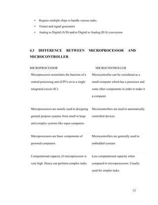
  • 12. 12 • Require multiple chips to handle various tasks. • Timers and signal generators • Analog to Digital (A/D) and/or Digital to Analog (D/A) conversion 4.3 DIFFERENCE BETWEEN MICROPROCESSOR AND MICROCONTROLLER MICROPROCESSOR MICROCONTROLLER Microprocessor assimilates the function of a central processing unit (CPU) on to a single integrated circuit (IC). Microcontroller can be considered as a small computer which has a processor and some other components in order to make it a computer. Microprocessors are mainly used in designing general purpose systems from small to large and complex systems like super computers. Microcontrollers are used in automatically controlled devices. Microprocessors are basic components of personal computers. Microcontrollers are generally used in embedded systems Computational capacity of microprocessor is very high. Hence can perform complex tasks. Less computational capacity when compared to microprocessors. Usually used for simpler tasks.
  • 13. 13 A microprocessor based system can perform numerous tasks. A microcontroller based system can perform single or very few tasks. Microprocessors have integrated Math Coprocessor. Complex mathematical calculations which involve floating point can be performed with great ease. Microcontrollers do not have math coprocessors. They use software to perform floating point calculations which slows down the device. The main task of microprocessor is to perform the instruction cycle repeatedly. This includes fetch, decode and execute. In addition to performing the tasks of fetch, decode and execute, a microcontroller also controls its environment based on the output of the instruction cycle. In order to build or design a system (computer), a microprocessor has to be connected externally to some other components like Memory (RAM and ROM) and Input / Output ports. The IC of a microcontroller has memory (both RAM and ROM) integrated on it along with some other components like I / O devices and timers.
  • 14. 14 The overall cost of a system built using a microprocessor is high. This is because of the requirement of external components. Cost of a system built using a microcontroller is less as all the components are readily available. Generally power consumption and dissipation is high because of the external devices. Hence it requires external cooling system. Power consumption is less. Instruction throughput is given higher priority than interrupt latency. In contrast, microcontrollers are designed to optimize interrupt latency.
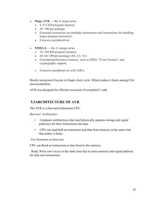
  • 15. 15 CHAPTER 5 AVR MICROCONTROLLER 5.1 INTRODUCTION Fig. 5.1 AVR AVR stands for Advanced Virtual RISC. The AVR is a modified Harvard architecture 8-bit RISC single chip microcontroller which was developed by Atmel in 1996. The AVR was one of the first microcontroller families to use on- chip flash memory for program storage, as opposed to one-time programmable ROM, EPROM, or EEPROM used by other microcontrollers at the time. 5.2 CLASSIFICATION OF AVR AVRs are generally classified into following:  Tiny AVR — the A tiny series  0.5–16 kB program memory  6–32-pin package  Limited peripheral set
  • 16. 16  Mega AVR — the A mega series  4–512 KB program memory  28–100-pin package  Extended instruction set (multiply instructions and instructions for handling larger program memories)  Extensive peripheral set  XMEGA — the A xmega series  16–384 KB program memory  44–64–100-pin package (A4, A3, A1)  Extended performance features, such as DMA, "Event System", and cryptography support.  Extensive peripheral set with ADCs. Mostly instruction Execute in Single clock cycle. Which makes it faster among 8 bit microcontrollers. AVR was designed for efficient execution of compiled C code. 5.3ARCHITECTURE OF AVR The AVR is a Harvard architecture CPU. Harvard Architecture • Computer architectures that used physically separate storage and signal pathways for their instructions and data. • CPU can read both an instruction and data from memory at the same time that makes it faster. Von Neumann architecture CPU can Read an instruction or data from/to the memory. Read, Write can`t occur at the same time due to same memory and signal pathway for data and instructions.
  • 17. 17 Fig. 5.2 Architecture of AVR  Connection of components with CPU within a Microcontroller is called a BUS. There are three types of bus: 1. Address Bus: It specifies the address. 2. Data Bus: It reads and writes on a specific address. 3. Control Bus: it controls the actions by sending and receiving messages, thus it is bidirectional. Key of microcontroller: 1. Register: it is a temporary storage and is a part of RAM. There are two types of registers- General Purpose Registers (GPR) and Specific Function Registers (SFR). GENERAL purpose  32 general purpose registers having storage capacity of 8 bit  Named as R0,R1,R2 to R31.  Register 0 to 15 & 16 to 31 are different.  Can store both Data & Addresses.
  • 18. 18 SPECIAL purpose: Three registers  Program counter  Stack Pointer  Status Register 2. Program Counter: it contains the address of next instruction to be executed by the CPU. It is also a register. 3. Accumulator: it is an intermediate register on which all Arithmetic and Logical operations are performed. 4. Clock Signals: these are digital signals which synchronize the action of a microcontroller. 5. Flash ROM: it is where the program code is stored. It is a fast erasing technology and erases all the contents at a time. 6. Interrupt: The interrupts refer to a notification, communicated to the controller, by a hardware device or software, on receipt of which controller momentarily stops and responds to the interrupt. 7. Stack: stack is used for the execution of the program. Whenever an interrupt occurs or a subroutine is called, the previous section of program is pushed onto the stack. After execution of the interrupt or the subroutine the execution is resumed from that part which was getting executed previously. 5.4 ATMEGA8 Fig. 5.3 Atmega8
  • 19. 19 5.4.1 ATmega8 - RISC Architecture ● 130 Instructions – Most Single-clock Cycle Execution ● 32 x 8 General Purpose Working Registers ● 64 x 8 Special Function Registers (I/O Registers) ● Up to 16 MIPS Throughput at 16 MHz ● On-chip 2-cycle Multiplier Nonvolatile Program and Data Memories ● 8K Bytes of In-System Self-Programmable Flash 10,000 Write/Erase Cycles ● Optional Boot Code Section with Independent Lock Bits ● 512 Bytes EEPROM (100,000 Write/Erase Cycles) ● 1K Byte Internal SRAM ● Programming Lock for Software Security Peripheral Features ● Two 8-bit Timer/Counters ● One 16-bit Timer/Counter with Capture Mode ● Real Time Counter with Separate Oscillator ● Three PWM Channels ● 6-channel ADC with 10 resp 8 Bit resolution (TQFP: 8 channels) ● Two-wire Serial Interface (TWI) ● Programmable Serial USART ● Master/Slave SPI Serial Interface ● Programmable Watchdog Timer with On-chip Oscillator ● On-chip Analog Comparator Special Microcontroller Features ● Programmable Brown-out Detection ● Internal Calibrated RC Oscillator ● External and Internal Interrupt Sources
  • 20. 20 ● Five Sleep Modes I/O and Packages ● 23 Programmable I/O Lines ● 28-lead PDIP, 32-lead TQFP, and 32-pad MLF Operating Voltages ● 2.7 - 5.5V (ATmega8L) ● 4.5 - 5.5V (ATmega8) Speed Grades ● 0 - 8 MHz (ATmega8L) ● 0 - 16 MHz (ATmega8) Power Consumption at 4 Mhz, 3V, 25°C ● Active: 3.6 mA ● Idle Mode: 1.0 mA ● Power-down Mode: 0.5 μA
  • 21. 21 5.4.2 Pin and Port Overview: Fig. 5.4 PDIP view of atmega8
  • 22. 22 Fig. 5.5 TQFP top view of atmega8 GND: Ground (0V) VCC: Digital Supply Voltage (2,7 – 5,5V) AVCC: Analog Supply Voltage connect to low-pass filtered VCC AREF: Analog Reference Voltage, usually AVCC /Reset: Low level on this pin will generate a reset Port B, Port C, Port D: General Purpose 8 Bit bidirectional I/O - Ports, Optional internal pull up-resistors when configured as input Output source capability: 20mA
  • 23. 23 Special Functions of the Ports available as configured using the SFRs: Port D: Uart, external Interrupts, Analog Comparator Port B: External Oscillator/Crystal, SPI Port C: A/D converters, TWI 5.4.3 ATMEGA 8 CORE ARCHITECTURE Fig. 5.6 Core Architecture of atmega8 ● Seperate Instruction and Data Memories (Harvard) ● all 32 General Purpose Registers connected to ALU
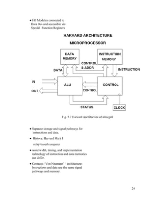
  • 24. 24 ● I/O Modules connected to Data Bus and accessible via Special Function Registers Fig. 5.7 Harvard Architecture of atmega8 ● Separate storage and signal pathways for instructions and data. ● History: Harvard Mark I relay-based computer ● word width, timing, and implementation technology of instruction and data memories can differ. ● Contrast: ‘Von Neumann’ - architecture: Instructions and data use the same signal pathways and memory.
  • 25. 25 Ability to fetch the next instruction at the same time it completes the current instruction. ● Speed is gained at the expense of more complex electrical circuitry. 5.4.4 Memory organization: Fig. 5.8 Memory Organization of Atmega8
  • 26. 26 ● Program Flash Memor y: On-chip, in system programmable 8 Kbytes, organized in 4K 16 bit words Program Counter (PC) = 12 bits Accessible via special instructions: LPM, SPM Boot Loader support: Boot Flash Section, SPM can be executed only from Boot Flash ● EEPROM - Memory: 512 Bytes, single Bytes can be read and written Special EEPROM read and write procedure using SFRs: EEPROM Address Register, EEPROM Data Register, EEPROM Control Register C – Library Functions available Precautions to prevent EEPROM memory corruption: ● No flash memory or interrupt operations ● Stable power supply
  • 27. 27 CHAPTER 6 PROGRAMS 6.1 7-segment display Fig. 6.1 7-Segment Display A seven-segment display (SSD), or seven-segment indicator, is a form of electronic display device for displaying decimal numerals that is an alternative to the more complex dot matrix displays. Seven-segment displays are widely used in digital clocks, electronic meters, basic calculators, and other electronic devices that display numerical information. 6.1.1 Introduction The 7 segment display can also be used for displaying numbers. Each of the segments of the display is connected to a pin on the 8051. In order to light up a segment on the pin must be set to 0V. To turn a segment off the corresponding pin must be set to 5V.
  • 28. 28 This is simply done by setting the pins on the 8051 to '1' or '0'. LED displays are Power-hungry (10mA per LED) and Pin-hungry (8 pins per 7-seg display). But they are cheaper than LCD display. 7-SEG Display is available in two types -1. Common anode & 2. Common cathode, but command anode display is most suitable for interfacing with 8051 since 8051 port pins can sink current better than sourcing it. Fig. 6.2 Types of 7-Segment Display 6.1.2 Creating Digit Pattern In Common Anode display, the common Anode pin is tied to 5v .The cathode pins are connected to port 1 through 330 Ohm resistance (current limiting). For displaying Digit say 7 we need to light segments -a ,b, c. in Common anode display , to do so we have to provide Logic -0 (0 v) at cathode of these segments. So need to clear pins- P1.0 ,P1.1,P1.2. That is 1 1 1 1 1 0 0 0 -->F8h. Digit Seg. h Seg. g Seg. f Seg. e Seg. d Seg. c Seg. b Seg. a HEX 0 1 1 0 0 0 0 0 0 C0 1 1 1 1 1 1 0 0 1 F9 2 1 0 1 0 0 1 0 0 A4 3 1 0 1 1 0 0 0 0 B0 4 1 0 0 1 1 0 0 1 99 Table 6.1: Hex Code for Displaying Various Digits
  • 29. 29 6.1.3 Multi 7 Segment interfacing Fig. 6.3 Interfacing Multi 7-Segment Display Since we can Enable only one 7-seg display at a time ,we need to scan these display at fast rate .the data lines are common for all the 4 segments The scanning frequency should be high enough to be flicker-free. At least 30HZ .Therefore – time one digit is ON is 1/30 seconds
  • 30. 30 6.1.4 PROGRAM FOR INTERFACING OF 7 SEGMENT DIPLAY WITH AVR MICROCONTROLLER #include <avr/io.h> #include <util/delay.h> int main(void) { DDRA = 0xFF; // Configure port B as output while(1) { //TODO:: application code PORTA = 0b00110000; // Display Number 1 _delay_ms(1000); // Wait for 1s PORTA = 0b01011011; // Display Number 2 _delay_ms(1000); // Wait for 1s PORTA = 0b01001111; // Display Number 3 _delay_ms(1000); // Wait for 1s PORTA = 0b01100110; // Display Number 4 _delay_ms(1000); // Wait for 1s PORTA = 0b01110111; // Display Letter A _delay_ms(1000); // Wait for 1s PORTA = 0b00111001; // Display Letter C _delay_ms(1000); // Wait for 1s PORTA = 0b01111001; // Display Letter E _delay_ms(1000); // Wait for 1s PORTA = 0b01110001; // Display Letter F _delay_ms(1000); // Wait for 1s } return 0;}
  • 31. 31 Fig. 6.4 Simulated Circuit 6.2LCD 6.2.1 Introduction A liquid-crystal display (LCD) is a flat panel display, electronic visual display, or video display that uses the light modulating properties of Liquid crystals. Liquid crystals do not emit light directly A liquid-crystal display (LCD) is a flat panel display, electronic visual display, or video display that uses the light modulating properties of Liquid crystals. Liquid crystals do not emit light directly
  • 32. 32 Fig. 6.5 LCD A liquid crystal display, is a thin, flat panel used for electronically displaying information such as text, images, and moving pictures. Its uses include monitors for computers, televisions, instrument panels, and other devices ranging from aircraft cockpit displays, to every-day consumer devices such as video players, gaming devices, clocks, watches, calculators, and telephones. Among its major features are its lightweight construction, its portability, and its ability to be produced in much larger screen sizes than are practical for the construction of cathode ray tube (CRT) display technology. Its low electrical power consumption enables it to be used in battery-powered electronic equipment. It is an electronically-modulated optical device made up of any number of pixels filled with liquid crystals and arrayed in front of a light source (backlight) or reflector to produce images in color or monochrome.
  • 33. 33 6.2.2 Program of 16x2 LCD interfacing with AVR microcontroller atmega8 #include <avr/io.h> void delay(unsigned char); //Main Code int main() { DDRB=0xff; //set PORTB as out put DDRD=0b01110000; //Set PD.4,5 and 6 as Output /* RS=PD5 R/W=PD6 E=PD4 */ //Give Inital Delay for LCD to startup as LCD is a slower Device delay(2); init_lcd(); while(1) { lcd_cmd(0x80); //Goto Line-1,first position lcd_send_string("WELCOME TO! "); lcd_cmd(0xC0); //Goto Line-2, first position lcd_send_string("EGLOB :) "); lcd_cmd(0x01); //Clear the lcd delay(1);
  • 34. 34 } } //LCD function /*------------------------------------------------------------------------------------------------------------*/ //Function for sending commands to LCD void lcd_cmd(unsigned char command) { //Put command on the Data Bus PORTB = command; //Enable LCD for command writing PORTD = 0b00010000; //Allow delay for LCD to read the databus delay(1); //Disable LCD again PORTD = 0b00000000; //Allow some more delay delay(1); } //Function for sending Data to LCD void lcd_data(unsigned char data) { //Put data on Data Bus PORTB= data; //Set R/S (Regiter Select) to High, and Enable to High PORTD = 0b00110000; //Allow for delay
  • 35. 35 delay(1); //Disable LCD again PORTD = 0b00100000; //Allow for some more delay delay(1); } //Function to send String to LCD void lcd_send_string(char* string) { while(*string) { //Send value of pointer as data to LCD lcd_data(*string); //Increment string pointer string++; } } //Function to Initilise LCD void init_lcd() { //Setup both lines of LCD lcd_cmd(0x38); //Set Cursor off - Enable LCD lcd_cmd(0x0E); //Clear Screen lcd_cmd(0x01); //Goto first position lcd_cmd(0x80); } /*----------------------------------------------------------------------------------------------------------*/ //Delay function
  • 36. 36 void delay(unsigned char dtime) { int i,j; for(i=0;i<=dtime;i++) { for(j=0;j<5000;j++); }} //You can use your own delay functions and replace this delay function with your code /*-----------------------------------------------------------------------------------------------------------*/ Fig. 6.6 Simulated Circuit