Transmission Control Protocol (TCP) and Starlink
0 likes•335 views

Geoff Huston, APNIC Chief Scientist, delivered a remote presentation on 'TCP and Starlink' at INNOG 8 held in conjunction with the 2nd India ISP Conclave held in Delhi, India from 23 to 28 May 2025.


Transmission Control Protocol (TCP) and Starlink
- 1. TCP and Starlink Geoff Huston AM APNIC APNIC 58
- 2. screenshot from starwatch app Screenshot: https://asia.nikkei.com/Business/Telecommunication/Elon-Musk-s-Starlink-launches-satellite-internet-service-in-Japan Screenshot - https://www.theverge.com/2022/8/25/23320722/spacex-starlink-t-mobile-satellite-internet-mobile-messaging LEOs in the News https://www.itnews.com.au/news/telstra-goes-live-with-starlink-for-homes-606423#:~:text=Telstra%20has%20kicked%20off%20its,the%20end%20of%20the%20year.
- 3. Newtonian Physics • If you fire a projectile with a speed greater than 11.2Km/sec it will not fall back to earth, and instead head away from earth never to return • On the other hand, if you incline the aiming trajectory and fire it at a critical speed it will settle into an orbit around the earth • The higher the altitude, the lower the orbital speed required to maintain orbit
- 4. Solar Radiation Physics • The rotating iron core of the Earth produces a strong magnetic field • This magnetic field deflects solar radiation – the Van Allen Belt • Sheltering below the Van Allen Belt protects the spacecraft from the worst effects of solar radiation, allowing advanced electronics to be used in the spacecraft
- 5. Low Earth Orbit • LEO satellites are stations between 160km and 2,000km in altitude. • High enough to stop it slowing down by “grazing” the denser parts of the earth’s ionosphere • Not so high that it loses the radiation protection afforded by the Inner Van Allen belt. • At a height of 550km, the minimum signal propagation delay to reach the satellite and back is 3.7ms, at 25o it’s 7.5ms. screenshot from starwatch app Image - spacex
- 6. Starlink Constellation If you use a minimum angle of elevation of 25o then at an altitude of 550km each satellite spans a terrestrial footprint of no more than ~900Km radius, or 2M K2 At a minimum, a LEO satellite constellation needs 500 satellites to provide coverage of all parts of the earth’s surface For high quality coverage the constellation will need 6x- 20x that number (or more!) 6
- 7. Starlink Constellation • 6,231 in-service operational spacecraft, operating at an altitude of 550km https://satellitemap.space/ 7
- 8. So LEOs are “interesting”! • They are very close to the Earth – which means: • They can achieve very high signal speeds • It’s a highly focussed signal beam • They are harder to disrupt by external interference • They don’t need specialised high-power equipment to send and receive signals • Even hand-held mobile devices can send and receive signals with a LEO (slowly!) • But you need a large number of them to provide a continuous service • The extremely host cost of launching a large constellation of LEO spacecraft has been the major problem with LEO service until recently • Which is why Motorola’s Iridium service went bankrupt soon after launch
- 10. Tracking a LEO satellite 550km 27,000 km/h Satellite horizon to horizon: ~5 minutes
- 11. Looking Up Starlink tracks satellites with a minimum elevation of 25o . There are between 30 – 50 visible Starlink satellites at any point on the surface between latitudes 56o North and South Each satellite traverses the visible aperture for a maximum of ~3 minutes 11
- 12. Starlink Scheduling • A satellite is assigned to a user terminal in 15 second time slots • Tracking of a satellite (by phased array focussing) works across 11 degrees of arc per satellite in each 15 second slot client 11o 15 seconds 12
- 13. Starlink Spot Beams • Each spacecraft uses 2,000 MHz of spectrum for user downlink and splits it into 8x channels of 250 MHz each • Each satellite has 3 downlink antennas and 1 uplink antennas, and each can do 8 beams x 2 polarizations, for a total of 48 beams down and 16 up. 13 “Unveiling Beamforming Strategies of Starlink LEO Satellites” https://people.engineering.osu.edu/sites/default/files/2022-10/Kassas_Unveiling_Beamforming_Strategies_of_Starlink_LEO_Satellites.pdf
- 14. Reported Capacity & Latency 14
- 15. Reported Capacity & Latency 15 Why is the Starlink carrier so unstable?
- 16. Starlink Scheduling • Latency changes on each satellite switch • If we take the minimum latency on each 15 second scheduling interval, we can expose the effects of the switching interval on latency • Across the 15 second interval there will be a drift in latency according to the satellite’s track and the distance relative to the two earth points • Other user traffic will also impact on latency, and also the effects of a large buffer in the user modem Loss Jitter
- 18. Varying SNR • Starlink likely uses IEEE 802.11ac dynamic channel rate control, adjusting the signal modulation to match the current SNR • This continual adjustment causes continual shift in the available capacity and imposes a varying latency on the round-trip time
- 19. Frames • Starlink does NOT provide each user with a dedicated frequency band • The system uses Multiplexing to divide a channel into frames, and sends 750 frames per second. Each frame is divided into 302 intervals. • Each frame carries a header that carrier satellite, channel and modulation information
- 20. Starlink Characteristics • Varying SNR produces varying modulation, which is expressed as varying capacity and delay • Relative motions of earth and spacecraft add to varying latency • 15 second satellite handover generates regular loss and latency extension • Contention for common transmission medium leads to queuing delays
- 21. TCP is the Internet • The Transmission Control Protocol is an end-to-end protocol that creates a reliable stream protocol from the underlying IP datagram device • This single protocol is the “beating heart” at the core of the Internet • TCP operates as an adaptive rate control protocol that attempts to operate efficiently and fairly
- 22. TCP Performance Objectives To maintain an average flow which is both Efficient and Fair Efficient: • Minimise packet loss • Minimise packet re-ordering • Do not leave unused path bandwidth on the table! Fair: • Do not crowd out other TCP sessions • Over time, take an average 1/N of the path capacity when there are N other TCP sessions sharing the same path
- 23. It’s a Flow Control process • Think of this as a multi- flow fluid dynamics problem • Each flow has to gently exert pressure on the other flows to signal them to provide a fair share of the network, and be responsive to the pressure from all other flows
- 24. TCP Control Data sending rate is matched to the ACK arrival rate TCP is an ACK Pacing protocol If the sender sends one packet each time it receives an ACK, then the sender will maintain a steady number of packets in flight within the network
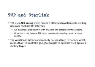
- 25. TCP and Starlink • TCP uses ACK pacing which means it attempts to optimize its sending rate over multiple RTT intervals • TCP assumes a stable carrier with low jitter and a stable channel capacity • When this is not the case TCP tends to reduce its sending rate to achieve stability • The variation in latency and capacity occurs at high frequency, which means that TCP control is going to struggle to optimize itself against a shifting target
- 26. How well does Starlink work? Speedtest measurements: We should be able to get ~180Mbps out of a Starlink connection. But Speedtest is NOT TCP – so lets look at TCP performance 26
- 27. “Classic TCP” – TCP Reno • Additive Increase Multiplicative Decrease (AIMD) • While there is no packet loss, increase the sending rate by one segment (MSS) each RTT interval • If there is packet loss (detected by duplicate ACKs) pause for 1xRTT and decrease the sending rate by 50% over the next RTT Interval by halving the sender’s send window • Start Up • Each RTT interval, double the sending rate • We call this “slow start” – probably because its anything but slow!!!
- 28. The Classic TCP Picture Queue formation Queue drain
- 29. CUBIC • CUBIC is designed to be useful for high-speed sessions while still being ‘fair’ to other sessions and also efficient even at lower speeds • Rather than probe in a linear manner for the sending rate that triggers packet loss, CUBIC uses a non-linear (cubic) search algorithm
- 30. CUBIC and Queue formation Total Queue Capacity (Onset of Packet Loss) Link Capacity Capacity (Onset of Queuing) Network Buffers Fill Network Buffers Drain
- 31. CUBIC assessment • Can react quickly to available capacity in the network • Tends to sit for extended periods in the phase of queue formation • Can react efficiently to long fat pipes and rapidly scale up the sending rate • Operates in a manner that tends to exacerbate ‘buffer bloat’ conditions
- 32. And there’s a whole lot more… TCP Variant Feedback RENO Loss AIMD Vegas Delay High Speed TCP Loss BIC Loss Binary Increase CUBIC Loss Cubic function increase - Linux-Adopted Agile-TCP Loss High Speed - Low Delay H-TCP Loss High Speed Fast Delay Akamai Propriatary Compound TCP Loss/Delay Microsoft Adopted Westwood Loss Dynamic setting of Slow Start Threshold Elastic TCP Loss/Delay High Speed - High Delay
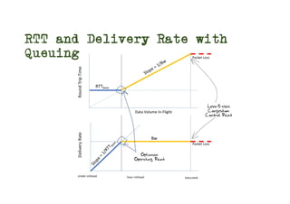
- 33. Optimising Flow State • There are three ‘states’ of flow management: • Under-Utilised – where the flow rate is below the link capacity and no queues form • Over-Utilised – where the flow rate is greater that the link capacity and queues form • Saturated – where the queue is filled and packet loss occurs • Loss-based control systems probe upward to the Saturated point, and back off quickly to what they guess is the Under-Utilised state in order to the let the queues drain • But the optimal operational point for any flow is at the point of state change from Under to Over-utilised, not at the Saturated point • We cen detect this point by careful handling of delay – the onset of queuing causes additional delay in the observed round trip time
- 34. Under-Utilised Over-Utilised Saturated RTT and Delivery Rate with Queuing
- 35. TCP Flow Control Algorithms “Ideal” Flow behaviour for each protocol RENO and CUBIC are loss-based control algorithms where the uppoer limit in the send rate is established by encountering packet loss BBR is a delay based control algorithm where the upper send limit is established by the onset of increased delay 35
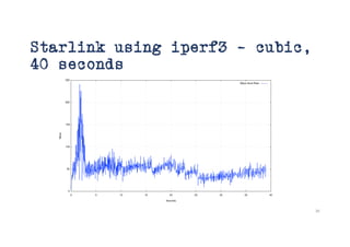
- 36. Starlink using iperf3 – cubic, 40 seconds 36
- 37. Starlink using iperf3 – cubic, 40 seconds 37 Slow Start Queue Drain Congestion Avoidance
- 38. Peak vs off-Peak - CUBIC Channel contention has a big impact on performance
- 39. Starlink with iperf3 – bbr, 40- seconds 39
- 40. Starlink with iperf3 – bbr, 40- seconds 40 15 second switch
- 41. From NANOG 92…
- 42. From NANOG 92… WHY does BBR outperform CUBIC on Starlink systems?
- 43. BBR Characteristics • BBR is not sensitive to packet loss, so the regular packet loss events every 15 seconds do not impact BBR performance • BBR uses even pacing of sent packets, so does not use network buffers to smooth out sender bursts • BBR does not perform continuous delay monitoring, but instead “spikes” the sending rate every 8 RTT intervals by a massive 25% • BBR only checks for a change in delay during this spike interval • This allows BBR to operate an internal model of channel capacity that is based on averaging across 8xRTT intervals, reducing its sensitivity to jitter and high frequency capacity changes
- 44. Protocol Considerations • Starlink services have three issues: • Very high jitter rates – varying signal modulation • High levels of micro-loss (1.4%) – largely due to 15s satellite handover events • Common bearer contention between users • Loss-based flow control algorithms will over-react and pull back the sending rate over time • Short transactions work very well • Paced connections (voice, zoom, video streaming) tend to work well most of the time • To obtain better performance you need to move to flow control algorithms that are not loss-sensitive, such as BBR
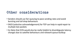
- 45. Other considerations • Senders should use fair queuing to pace sending rates and avoid bursting and tail drop behaviours • SACK (selective acknowledgement) for TCP can help in rapid repair to multiple lost packets • Its likely that ECN would also be really helpful to disambiguate latency changes due to satellite behaviours and network queue buildup
- 46. Starlink Performance Starlink is perfectly acceptable for: • short transactions • video streaming • conferencing • The service can sustain 40 – 50Mbps delivery for long-held sessions during local peak use times in high density use scenarios • The isolated drop events generally do not intrude into the session state • In off-peak and/or low-density contexts it can deliver 200-300Mbps • It can be used in all kinds of places where existing wire and mobile radio systems either under-perform or aren’t there at all! • Its probably not the best trunk infrastructure service medium, but it’s a really good high speed last mile direct retail access service, particularly for remote locations!
- 47. Making Starlink Faster • Increase antennae transmitter power • Use higher gain antennae with narrower beams • Drop the orbital altitude to 340Km • Drop the minimum elevation angle from 25o to 20o • Use more bands (Ka-, V-, and E- bands) (Proposed measures described in an October 2024 FCC application by Starlink)
- 48. Questions?