SlideShare a Scribd company logo
ArchiCADversion 7.0
Step by Step Tutorial
by Thomas M. Simmons
US version
BUDAPEST • MUNICH • SAN FRANCISCO • TOKYO • LONDON • MADRID • SAÕ PAULO • SANTIAGO DE CHILE
ArchiCAD Step by Step Tutorial, version 7.0
© 1998-2001 by Thomas M. Simmons. All rights reserved. Reproduction, paraphrasing or translation
without express prior written permission of the author and Graphisoft is strictly prohibited.
The Nokia K2 project used for illustrating the ArchiCAD package and book covers is copyrighted by
and used with the permission of Helin & Co. Architects, Helsinki, Finland.
Published by GRAPHISOFT R&D Rt., http://www.graphisoft.com
First edition.
Printed in Hungary.
ArchiCAD is a registered trademark and PlotMaker, Virtual Building, StairMaker and GDL are
trademarks of Graphisoft. Windows is a trademark of Microsoft Inc. Macintosh, Power Macintosh,
QuickTime and TrueType are registered trademarks of Apple Computer Inc.
ISBN 963 00 6850 8
About the Author
Thomas M. Simmons
President
ARCHVISTA
The ArchiCAD Step by Step Tutorial was developed by ARCHVISTA and used
with the ArchiCAD training course at the San Francisco Institute of Architects.
This is the first edition of Step by Step produced for ArchiCAD 7.0.
The author, Thomas M. Simmons, spent seven years as an architect and served
as the director of design technology for Esherick, Homsey, Dodge and Davis
Architects, an award-winning and internationally acclaimed architecture firm,
before starting his company, ARCHVISTA. While at EHDD Architects, he was
instrumental in integrating and managing ArchiCAD on projects ranging from
single-family houses, commercial buildings, libraries and aquariums.
Simmons received a Master of Architecture degree from the University of
California, Berkeley, and a Bachelor of Environmental Design degree from
Texas A & M University. He has been a speaker on a variety of subjects
including Beginning to Advanced ArchiCAD, Architectural Multimedia,
QuickTime VR and Architectural Visualization.
ARCHVISTA has produced several notable projects for the architectural and
ArchiCAD markets including the award-winning Architectural Record, Record
Houses CD-ROM - 1997 and 1998 and the award winning visualization of the
American Hebrew Academy with Aaron Green Architects. Additionally,
ARCHVISTA has produced two products for ArchiCAD: ProjectStart and
ProjectResource, management and organizational utilities.
Tutorial archi cad 7.0
1
Introduction
ArchiCAD Step by Step Tutorial
Introduction
Welcome to Step by Step
The Step by Step Tutorial for ArchiCAD 7.0 is designed as a 16- to 20-hour
course that will guide you through a project. By the end of this course, you
should have a basic understanding of ArchiCAD concepts, tools, drawing
techniques and modeling. The steps highlight the implementation of a project,
methods of design and the application of tools for construction documents.
The intention of this course is to offer a consistent and organized process for
learning ArchiCAD based on an architectural project.
Each step guides you through the concept or technique to be learned, the
information necessary to build the exercise, and what to do for that step. The
steps also contain diagrams of Toolbox and dialogs that provide quick
references to Tools used in that exercise.
Important Note on the Step Files
The ArchiCAD Step by Step Tutorial has been designed to introduce the
program’s functionality to users who have purchased a commercial or
educational license.
If you have purchased or been offered Step by Step for evaluation purposes, the
Step by Step CD-ROM contains a demo version of ArchiCAD. While offering the
full functionality of the software, this demo version contains security
restrictions. For example, you cannot save files or create a team project. This
means that you will not be able to do some of the exercises as described in the
manual.
2
Introduction
ArchiCAD Step by Step Tutorial
The Concept of a Virtual Building
Architectural software is evolving rapidly from an “automator” of two-
dimensional drafting to a three-dimensional building simulator. As a result of
this evolution, the architect’s ability to construct a “virtual building” on a
desktop computer, to simulate the building’s behavior both before it is built
and throughout its life cycle, will change the architect’s design process, fee
structure, and relationship with the client, contractor and the community. In
addition to transforming the architect’s own practice, ownership of the 3D
computer model will carry important competitive advantages in procuring all
future work associated with the same building.
Traditional CAD vs. Virtual Building Technology
So what is the difference between traditional CAD drafting and Virtual Building
Technology? Traditional CAD is the world of lines, arcs, circles and blocks.
With traditional CAD, your drawing is a 2D representation of how the building
will be built. It is very similar to hand drafting but automated with computer
technology.
With Virtual Building Technology, you construct a building using building
elements: floor slabs, walls, roofs, windows, doors, stairs and other objects. A
Virtual Building uses intelligent objects to create building elements. With object
oriented CAD each object in the system represents a building element with a
behavior and intelligence relevant to that element. For example, the behavior
of a door is different than the behavior of the wood used to construct it.
Because you have the real model of a building, not just a 2D representation of
one, you can ask it building specific questions. For instance, you can get
detailed reports on egress analysis, heat loss analysis, code compliance or cost
takeoffs.
From the Virtual Model, buildings can be analyzed with respect to building
mass, overshadowing and visual appearance. ArchiCAD can automatically
generate plans, elevations and sections, perspective views, animations and
virtual reality views.
Integrated Building Information
Architects and building professionals using integrated 3D CAD software
generate a wealth of valuable building information that can be used for both
the traditional architectural practice as well as for many new fields and
services. Some of the opportunities that can utilize this information are:
• Building master planning, design and development
• Creation of renderings, animations and virtual reality scenes
• Production drawings, details and schedules
• Building marketing
3
Introduction
ArchiCAD Step by Step Tutorial
• Management of building spaces and assets
• Post-occupancy studies and simulation of design changes
• Analysis and visualization of product performance over the building life
cycle
• Content development for electronic building component objects including
product data and links to manufacturer Websites
With ArchiCAD and its Virtual Building Technology, architects, in partnership
with owners, are in a prime position to assert their central role not only in the
initial design of buildings, but also in their long-term programming,
maintenance and operation.
How Firms use ArchiCAD
As the new age of Virtual Building Technology unfolds, architecture firms and
the building industry must consider how to effectively apply Virtual Building
Technology to design, production, collaboration and information analysis.
ArchiCAD offers a complete solution and, unlike other CAD systems, has been
built on the foundation of architecture.
With this in mind, there are a variety of architecture firms using ArchiCAD and
its Virtual Building Technology system. The firms range in size from one man
firms to several hundred and specialize in a variety of projects including
housing, retail, commercial, schools and others. Here is what several architects
have to say about ArchiCAD and their use of Virtual Building Technology:
House+House Architects (San Francisco, California)
“Part of ArchiCAD’s value lies in modeling and easy perspectives; you do not
need to put a lot of effort into it,” Steven House said. “But it is worth it to take
the extra step to create views with a different flavor. The results can be very
powerful.”
House+House are very hands on with their projects, working closely with
builders, artisans and craftsmen to ensure that no detail goes unconsidered.
“We are very excited about our explorations in ArchiCAD,” Steven said. “And
the potential it offers for us to communicate design ideas to our clients, our
builders and ourselves.”
STUDIOS Architecture (Washington, D.C.)
With a tight project timeline, the design team at STUDIOS appreciated
ArchiCAD’s ability to generate three-dimensional models automatically from
the floor plan and section views allowing them to advance the construction
documents, make design studies and prepare client presentations at the same
time with relatively little additional work.
4
Introduction
ArchiCAD Step by Step Tutorial
“Modeling in 3D gives you and your client a chance to look at a design
critically and react to it,” project architect Bill Deegan said. Deegan also cites
that STUDIOS could shave off critical time by sending QuickTime VR scenes to
the client by e-mail and through an Intranet which links STUDIOS U.S. offices
in Washington, D.C., San Francisco and New York.
The Orcutt/Winslow Partnership (Phoenix, Arizona)
When Orcutt/Winslow began to fully embrace the Virtual Building method of
working, they had to rethink their billing process. “The time spent on the
project is greater up-front, but the documents phase time and effort has been
significantly reduced,” Winslow said. ArchiCAD’s single, integrated database
allows them to start the input of specific materials and systems at a much
earlier point in the design phase. With this method, they can show these details
at any point, and comfortably make modifications because any changes made
will be updated in all views. “Our schematic designs show a much more
complete three-dimensional presentation to the client and allow us to evaluate
the design in 3D more thoroughly at early stages.”
“Office morale and profitability are both on the rise and we are currently in
the process of shifting our project phasing percentages to take into account the
Virtual Building methodology,” added project manager Russ Sanders. “More
time is expended up front establishing the links from the primitive model to the
layout sheets. Once this is done, the rest of the project can be developed within
the model. By the time we have completed the design development phase, we
are actually about 60 percent complete with construction documents.”
Rockefeller/Hricak Architects (Venice, California)
“We would like to think that the appearance of our work is a direct result of
how it gets built. Using ArchiCAD to build a ‘living’ model of the building helps
us to focus on issues and assist us in making design decisions as the project
takes shape.” The firm is concerned not just how buildings look, but also how
they function over time.
“We need to be able to predict how the building will look 10 to 20 years down
the road, because that affects the way we design it,” Hricak said. “If something
is going to wear out in 20 years, we need to understand how that element
interacts with what is around it. Obviously the structure is not going to wear
out, but windows will be repaired, and equipment will become obsolete.
ArchiCAD helps us be clear about the separation of systems and get a sense of
how the building will perform.”
5
Introduction
ArchiCAD Step by Step Tutorial
How the Book and CD-ROM Work Together
The book is divided into seven sections beginning with the introduction of
concepts then moving through the construction of a Virtual Building. The
interactive CD-ROM acts as a virtual assistant that answers questions with real-
time movies of each step. All you need to use the interactive is a standard web
browser.
Whenever you see this icon...
...it means there is a QuickTime movie demonstrating the step. To view the
movie, insert the Step by Step Tutorial CD-ROM into your computer’s CD-ROM
drive. Open the CD-ROM and double-click the file called Step Interactive. This
will open into your default web browser.
To locate the corresponding movie for a step, use the information under the
CD-ROM icon.
Part 1 - Indicates the main section, Part 1: Concepts and Tools
Step 4 - Indicates the step, Step 4: Editing and Notation
Movie C - Indicates the movie designation for Step 4, Movie C - Multiply Exercise
No 1 - 4 - Indicates the exercise numbers if the movie refers to more than
one exercise
To play the QuickTime movie, simply click the name of the movie (the name in
color with an underline), such as Movie C - Multiply Exercise. The screen will
jump to the movie and begin playing it.
It is that simple!
6
Introduction
ArchiCAD Step by Step Tutorial
How to Install and Use the Step Files and
the Demo Version of ArchiCAD 7.0 on
Windows
Insert the Step by Step CD-ROM into your computer’s CD-ROM drive. The main
dialog box of the installation appears on your screen, where you can choose
from four options by single clicking on the appropriate caption:
• Install Step by Step Tutorial
If you have an installed ArchiCAD 7.0 on your hard drive and you need only
the Step Files and the Tutorial, click Step by Step Tutorial and follow the
installation procedure. Once completed, the requested items appear in the
existing ArchiCAD 7.0 folder. Double-click on them and discover your new
ArchiCAD files and Tutorial.
Library Manager
If you try to open a Step file and the Library Manager dialog box appears,
asking where the ArchiCAD Object Library is located on your hard drive, you
must:
1. locate the ArchiCAD folder,
2. open it and select the folder called ArchiCAD Library 70,
3. click the Add button in the center of the dialog box,
4. click the Done button.
7
Introduction
ArchiCAD Step by Step Tutorial
• Install ArchiCAD 7.0 Demo
If you wish to install a Demo version of ArchiCAD on your hard drive, click
ArchiCAD 7.0 Demo and follow the installation procedure.
A dialog box will suggest the location of the installation on your hard drive, but
you can select another hard disk for the ArchiCAD Demo version.
Once completed, the ArchiCAD 7.0 Demo folder will appear in the specified
place. Double-click on ArchiCAD.exe contained in the ArchiCAD 7.0 Demo folder
and discover your new application.
• Browse this CD
If you wish to see or use the contents of the CD directly, click Browse this CD.
• Exit
If you wish to close the main dialog box and finish using the Step by Step
Tutorial CD, click Exit.
8
Introduction
ArchiCAD Step by Step Tutorial
How to Install and Use the Step Files and
the Demo Version of ArchiCAD 7.0 on
MacOS
Insert the Step by Step Tutorial CD-ROM into your computer’s CD-ROM drive.
The contents of the CD-ROM will appear on your screen.
• Install Step by Step Tutorial
If you have an installed ArchiCAD 7.0 on your hard drive and you need only
the Step Files and the Tutorial, click Step by Step Installer. A dialog box will
ask for the location of your ArchiCAD folder. Click the Select Folder button to
browse your computer for the requested folder. Click Continue and follow the
installation procedure.
Once completed, the requested items appear in the existing ArchiCAD 7.0
folder. Double-click on them and discover your new ArchiCAD files and
Tutorial.
9
Introduction
ArchiCAD Step by Step Tutorial
Library Manager
If you try to open a Step file and the Library Manager dialog box appears,
asking where the ArchiCAD Object Library is located on your hard drive, you
must:
1. locate the ArchiCAD folder,
2. open it and select the folder called ArchiCAD Library 70,
3. click the Add button in the center of the dialog box,
4. click the Done button.
• Install ArchiCAD 7.0 Demo
If you wish to install a Demo version of ArchiCAD on your hard drive, follow
the instructions below:
- Open the folder called ArchiCAD 7.0 Demo located on the Step by Step
Tutorial CD-ROM.
- Double-click on the Installer icon. A dialog box will suggest the location of
the installation on your hard drive, but you can select another folder for
the ArchiCAD Demo version.
- Click Continue. Once completed, the ArchiCAD 7.0 Demo folder will
appear in the specified place.
- Double-click on the ArchiCAD icon contained in the ArchiCAD 7.0 Demo
folder on your hard drive and discover your new application.
10
Introduction
ArchiCAD Step by Step Tutorial
Using the ArchiCAD 7.0 Demo Version
Double-click on the ArchiCAD.exe (PC) / ArchiCAD 7.0 icon (MAC), to start
the ArchiCAD 7.0 Demo version. The Welcome to ArchiCAD information box
appears:
Starting a Tutorial Exercise
When the ArchiCAD 7.0 version is open on screen, go to the File Menu and
Open the file Step-xx.pln located in the Step Files folder.
11
Introductory Step: Introduction to ArchiCAD
ArchiCAD Step by Step Tutorial
PART ONE:
CONCEPTS AND TOOLS
1. INTRODUCTION TO ARCHICAD
2. TOOLS AND PALETTES
3. CURSOR FORMS
4. EDITING AND NOTATION
5. THE 3D ENVIRONMENT
6. UNDERSTANDING LIBRARIES
12
Introductory Step: Introduction to ArchiCAD
ArchiCAD Step by Step Tutorial
Introductory Step:
Introduction to ArchiCAD
Overview
The Introductory Step begins with ArchiCAD’s workplace. Here you will learn
the basic windows of the working environment and how to customize these
windows to create your personal workspace.
This exercise will also introduce the concepts of objects and how an object’s
parameters influence the way it is defined.
Process to Learn
• ArchiCAD Workplace
Floor Plan Window
Section/Elevation Window
3D Window
• Concepts of Parametrics
• ArchiCAD’s Help System
Starting the Step
To begin this step, double-click the file named Introductory Step.pln contained
in the Step Files folder.
13
Introductory Step: Introduction to ArchiCAD
ArchiCAD Step by Step Tutorial
The ArchiCAD Workplace
This step introduces the visible elements of the ArchiCAD working
environment. They will help you find your way around the ArchiCAD
workplace and understand the role each component plays in using ArchiCAD.
In many respects, the ArchiCAD workplace is similar to conventional design
and drafting environments. We like to think that ArchiCAD begins where your
drafting table leaves off.
The ArchiCAD workplace is designed to provide you with tools that look and
feel comfortable, but have all the power and precision available to a
computerized system.
The Introductory Step opens to the ground floor of a two-story building. Here
we can view the three components of ArchiCAD’s workplace. These three
workspaces are linked working environments. The working environment
allows an interactive drawing process between the Floor Plan, Section/
Elevation and 3D Window. Elements are updated in all views to reflect
current changes to the model.
• Floor Plan Window
14
Introductory Step: Introduction to ArchiCAD
ArchiCAD Step by Step Tutorial
• Section/Elevation Window
• 3D Window
15
Introductory Step: Introduction to ArchiCAD
ArchiCAD Step by Step Tutorial
The Floor Plan Window
The center of the ArchiCAD workplace is the Floor Plan worksheet. This
Window plays two roles at the same time:
- It displays a representation of the project as a traditional architectural
drawing.
- It is a 2D/3D modeling environment that is interactive with the Sections/
Elevations and 3D workspace.
With the Floor Plan window open, we can view the plans for both floors of
this building. To move up a story, click on Stories in the QuickViews floating
Palette (normally displayed on the right) and then double-click on Upper
Floor. The use of the QuickViews Palette is explained in detail in Step 2.
The Floor Plan worksheet is like a sheet of drafting paper. However, a
traditional mechanical drafting board is limited by the size of the paper you can
fit on it, while the ArchiCAD worksheet can be as big as you want it to be. You
can pan and zoom the Window within the full drawing space to obtain the best
view of the work you are doing.
16
Introductory Step: Introduction to ArchiCAD
ArchiCAD Step by Step Tutorial
The Section/Elevation Window
Using the Section/Elevation Tool in the Toolbox, you can generate any
number of sections or elevations of your project, which will appear in separate
Windows.
The Section/Elevation Window is interactively linked to both the Floor Plan
and 3D Windows. Elements selected in this Window are recognized as walls,
beams, columns, slabs, roofs, windows, doors, lights and library parts. These
elements are fully editable using the same editing tools as you use in the Floor
Plan workspace.
You can also add drawing elements to this Window using the 2D drafting tools,
place objects and text blocks on the section/elevation and even copy and paste
parts of the Window to the floor plan for completing detailed working
documents.
Section/Elevation views are saved with your project model file. It is also
possible to save them as separate files in a variety of drawing formats using the
Save As... command under the File menu.
17
Introductory Step: Introduction to ArchiCAD
ArchiCAD Step by Step Tutorial
The 3D Worksheet Window
The 3D Window is used for three-dimensional visualization of the
architectural project and as a project editing environment.
Either the complete project or just the parts you select in plan view will be
displayed in the 3D Window. Block, Wireframe, Hidden line and Shaded
views are available in all types of parallel and perspective projections. The 3D
Window serves a variety of functions:
- In your design phase, the 3D Window will serve as a source for visual
feedback of your work.
- It is an interactive Window, so you can move freely about in the 3D
environment both in Parallel and Perspective projections.
- The elements in this Window, as in the Floor Plan and Section/
Elevation Windows, are completely editable.
- For PhotoRenderings, the 3D Window sets the view that will be used to
produce a final photorendering.
- For output to other applications, a 3D file can be exported from the 3D
Window.
18
Introductory Step: Introduction to ArchiCAD
ArchiCAD Step by Step Tutorial
The Concept of Parametrics
An ArchiCAD innovation, parametric object definition allows a single stored
object (i.e., window, door, light, stair or truss) to represent dozens of similar
objects by simply changing their height, thickness, material and other custom
parameters. Each object can also be re-saved under another name allowing you
to quickly build up your own specific library.
To view an example of how parameters are used, double-click on the Window
Tool in the Toolbox. The dialog contains various parameters that can create a
window with different forms, shapes, sizes and materials.
To make changes to the selected window, click in any of the Parameters fields
with your cursor and change the settings (i.e., width, depth, length, height).
As you change the settings, view the window in top view, side view, hidden
line 3D view, shaded 3D view and as a preview picture using the Display
Mode buttons.
You can choose between window objects using the thumbnail previews in the
browser at the top of the dialog, by selecting a different window library from
the list on the left-hand side of the dialog box or by choosing another catalog
with the Load Window button top right.
19
Introductory Step: Introduction to ArchiCAD
ArchiCAD Step by Step Tutorial
ArchiCAD’s Help System
ArchiCAD has several help systems in place:
1. Click on any interface item to display a help by explaining the use of the items.
2. When you begin an action, the Prompt Box will prompt you for the next
action. The Prompt Box is part of the Control Box (another floating palette,
normally situated bottom right) and can be displayed by clicking on the
prompt icon (Mac) or maximize icon (Windows) in the upper right corner of
the Control Box.
3. Integrated into ArchiCAD is the ability to launch several separate sources of
help documentation in HTML or PDF format that can be viewed while still in
the ArchiCAD application. To access the documentation, go to the Help menu
and select the desired subject.
20
Step 1: Virtual Building Basics
ArchiCAD Step by Step Tutorial
Step 1:
Virtual Building Basics
Overview
In this first exercise, you will see how the Virtual Building works by drawing a
simple set of elements in Floor Plan view, and then examining them in the 3D
Window and in a calculation list.
Process to Learn
• Creating Walls
• Insert Objects
• Change Wall Properties
• Creating a Calculation List
Starting the Step
To begin this step, double-click the file named Step-01.pln contained in the
Step Files folder.
21
Step 1: Virtual Building Basics
ArchiCAD Step by Step Tutorial
Introductory Exercise
The following exercise will demonstrate a simple introduction to the ArchiCAD
environment. You will create two simple intersecting walls, insert an object into
the wall, and create a quick 3D view of the results. As you follow this exercise
it is not necessary that your information and settings exactly match those
shown.
Double-click the ArchiCAD file named Step-01.pln in the Step Files folder. You
can use this file to begin the following exercise.
The Wall Tool should be active in the Toolbox. Move your cursor to the upper
left part of your screen and click once with the mouse to set the beginning of
the wall. Move the cursor horizontally to the right with the Shift key held
down. Click again to finish the wall. Your wall should look similar to the one
below.
Go to the Window Menu and select 3D Window to see a 3D view of the wall
that you built. The wall that you drew in plan is not just a 2D wall made up of
lines and fills, but an actual object. It is a wall with various architectural
building properties. Select Floor Plan to return to the Floor Plan Window.
Double-click on the Wall Tool in the Toolbox. A dialog box appears that
allows you to customize the properties of selected walls or new walls that are
yet to be drawn. Change the wall construction by clicking and holding on the
existing fill pattern. A pop-up menu will appear. Here you can select other wall
properties. These changes affect the wall globally, in plan, elevation, section,
3D and in listing information. Select the fill indicated below by moving your
cursor in the pop-up menu.
CD-ROM
Part 1
Step 1
Movie A
22
Step 1: Virtual Building Basics
ArchiCAD Step by Step Tutorial
Draw a new wall and notice the fill pattern and plan dimensional changes.
Select Undo from the Edit Menu (twice) to undo the two walls that you drew.
Now select the Wall Tool again and draw a new wall. This time hold the Shift
key down before clicking to end the wall. This will constrain the wall either
horizontally or vertically; draw a horizontal wall. To connect a wall to this new
wall, place the Cursor on the corner shown. The Cursor changes to a
Checkmark, indicating that the cursor is perfectly aligned with that corner of
the wall.
Once the Cursor appears, draw another wall, but this time vertically, with the
Shift key held down. The walls should look similar to those below.
23
Step 1: Virtual Building Basics
ArchiCAD Step by Step Tutorial
To see the clean intersections, turn the Clean Wall & Beam Intersections ON in
Options/ Display Options.
Now double-click on the Window Tool. This dialog allows you to customize
the settings for a selected window. Select a window and review the different
settings. In this case use the defaults.
With the Window Tool selected, move the cursor over one of the walls until it
changes into a Mercedes form. Now click on the wall. A hole appears where
the window will be placed. Next click to define on which edge of the wall
opening the window will actually be placed.
24
Step 1: Virtual Building Basics
ArchiCAD Step by Step Tutorial
Now go to the Window Menu and select 3D Window to see a 3D view of the
wall and placed window. To see a wireframe view as in the image on the right,
go to the Image Menu and select Shading.
Select Floor Plan from the Window Menu. Now select List Elements from
the Calculate Menu and choose Basic. This creates a simple list of information
that tracks all the drawn building elements and their related information. The
list you created here is very simple, but you can gather information such as
material, surface finish, quantity, volume, price, etc. All this listed information
changes dynamically as any changes are made in the Floor Plan, Section/
Elevation, 3D or Tool Setting.
These exercises are just an introduction to ArchiCAD. The tools, dialog boxes,
and information presented here and the following chapters are very powerful
and integrated, yet always easy to learn and use. The rest of this manual will
guide you through the ArchiCAD application in more detail.
25
Step 2: Tools and Palettes
ArchiCAD Step by Step Tutorial
Step 2:
Tools and Palettes
Overview
The second step will review the five main palettes used by ArchiCAD. This will
give you an overview of the purpose of the palette and how to access and use
them.
This exercise will also demonstrate how to customize the palette shapes and
sizes for your individual setup.
Process to Learn
• Customizing the Workplace
• Toolbox
• Info Box
• Coordinate Box
• Control Box
Starting the Step
Open a new ArchiCAD file with the default settings. To do this, hold down the
Alt key (Windows) or Option key (Macintosh), then go to the File Menu and
choose New and reset, or open the file named Step-02.pln contained in the
Step Files folder.
26
Step 2: Tools and Palettes
ArchiCAD Step by Step Tutorial
What to Do
Customizing the Workplace: The Tools and Palettes can be customized to
your preferences. To do this, go to the Window Menu and select Floating
Palettes/Palette Shapes. Here you can change the shape and size of your
Palettes. Also, each individual Palette can be turned on or off by selecting
Hide/Show.
1. The Toolbox: The Toolbox is where you start in ArchiCAD. The Toolbox is
divided into five basic parts: Selection Tools, 3D Tools, Notation Tools, 2D
Tools and Visualization Tools.
Arrow
Wall
Beam
Door
Lamp
Roof
Dimension
Level
Text
Zone
Fill
Circle/Arc
Fiqaure
Section
Stair
Marquee
Column
Window
Object
Slab
Mesh
Radial Dimension
Angle Dimension
Label
Line
Spline
Hot Spots
Camera & QTVR
(Toolbox is shown as expanded)
• Review the Tool Settings Dialogs: Each Tool has a settings dialog associated
with it. To review the dialogs for each Tool, double-click the Tool.
Note: that each tool has various settings for Floor Plan, Section, Model and
Properties. The Wall Settings dialog is typical of the basic settings for each
of the 3D Tool settings.
Figure
27
Step 2: Tools and Palettes
ArchiCAD Step by Step Tutorial
The Library Settings dialog (shown below) is similar for all library parts
which includes windows, doors, lamps, objects and stairs. This dialog contains
a library part browser at the top and a system explorer tree to the left. You can
customize the view of the dialog.
2. Info Box: The Info Box allows you to easily choose among construction
methods, change geometry methods, and view instant feedback on the
elevation, layer information and ID number of construction elements. It also
28
Step 2: Tools and Palettes
ArchiCAD Step by Step Tutorial
allows you to reach the most important settings of any element and directly
modify some of their parameters. The items displayed in the Info Box vary
according to which ArchiCAD Tool is currently selected.
• Review the Controls for Each Tool: In this exercise, click each Tool in the
Toolbox and observe how the Info Box settings differ for each Tool selected.
A few typical controls are shown below:
3. Coordinate Box: The Coordinate Box shows you the precise location of the
ArchiCAD Cursor within both the Cartesian and the polar coordinates for your
drawing. This allows the entering and the viewing of very accurate numeric
information through the keyboard, in addition to or instead of the mouse. This
Box also allows you to turn the Snap Grid on or off, turn Gravity on or off,
and move the User Origin.
• Draw a Wall Segment: Drawing information numerically input through the
keyboard can be used to define specific angles, lengths or location points. With
the triangle depressed in the Coordinate Box, click to start drawing a wall.
Enter 4'-8" for x, 0 for y and Return. You now have a 4'- 8" wall.
1. Click to start wall. 2. Type in the 3. Hit Return or Enter
coordinates. to finish.
4. Control Box: The Control Box gives you the ability to constrain the drawing
angle and cancel or confirm the current drawing operation. It also allows you
to group or ungroup elements, choose extension line settings, select offsetting
commands, and provides active Tool specific help in the Command Prompt
area during different drawing steps.
CD-ROM
Part 1
Step 2
Movie A
29
Step 2: Tools and Palettes
ArchiCAD Step by Step Tutorial
• Review the Control Box: Select different Tools from the Toolbox and draw a
simple shape with each one. Observe the Command Prompt area during the
tool operations for help.
Expanded Control Box with Command Prompt
30
Step 3: Cursor Forms
ArchiCAD Step by Step Tutorial
Step 3:
Cursor Forms
Overview
In this step, you will learn how ArchiCAD’s intelligent Cursor provides
automatic snaps, editing and selection functions. The Cursor is designed to
change form as it responds to a variety of functions in the working
environment.
This step will explore techniques of applying Cursor forms to drawing methods.
Process to Learn
• The Intelligent Cursor
Types of Cursor Forms
Functions of the Cursor
Starting the Step
To begin this step, double-click the file named Step-03.pln contained in the
Step Files folder.
31
Step 3: Cursor Forms
ArchiCAD Step by Step Tutorial
Information
ArchiCAD uses an intelligent Cursor to aid, simplify and speed the drawing
process. Various Cursor forms are used by ArchiCAD depending on the type of
Tool and function selected. As you work in ArchiCAD, you will see that in
different locations or situations the Cursor will change shape, informing you
about its relation to existing elements or actions expected from you.
What to Do
1. Empty Pencil: Select the Wall Tool and begin drawing a wall. An Empty
Pencil will appear after you begin drawing with the Tool. This indicates that
you are in the drawing mode. Click again to complete the wall.
2. Cross Hair: Move the Cursor away from the wall and note that your Cursor
appears as a Cross Hair. This indicates that ArchiCAD is waiting for you to
begin an operation using that Tool.
3. Arrow: Select the Arrow Tool in the Toolbox and note that the Cursor is now
shown as an arrow. This is your selection Tool.
4. Checkmark: Drag your Tool over the corner of the wall. A Checkmark will
appear indicating that the Cursor is snapping to the corner. The Checkmark
will appear differently for each side of the wall. This is because ArchiCAD uses
a construction line to automatically clean up wall intersections. The Heavy
Checkmark indicates the construction line side of the wall. To see the
construction line, turn Wall & Beam Intersections to No in Options/
Display Options.
Turn Wall & Beam Intersections to Yes again.
Select the Wall Tool and the Checkmark becomes a simple check.
CD-ROM
Part 1
Step 3
Movie A
No 1 - 9
32
Step 3: Cursor Forms
ArchiCAD Step by Step Tutorial
5. Filled Pencil: Click again as indicated in the diagram and drag the Empty
Pencil across the edge of the wall. Note the different Cursor forms that indicate
which side of the wall is the active construction line.
6. Perpendicular Sign: Now drag the Striped Pencil to a point that appears
perpendicular to the wall. The intelligent Cursor will indicate you are snapping
to a perpendicular edge.
7. Striped Pencil: Now drag the Empty Pencil across the end of the wall. Note
that on the end of the wall the pencil shows as filled. This is because a wall has
a hot point at the four corners.
8. Intersection: Now draw a line crossing the other wall as shown. Drag your
Cursor to the intersection of the two walls. The cursor changes to a
Crosspoint, indicating that you are snapping to an intersection.
9. Mercedes Sign: Now put your Cursor alongside the edge of the wall. Notice
how it changes to a Mercedes sign. This indicates that you are snapping to an
edge. Note the different Cursor forms that indicate which side of the wall is the
active construction line.
33
Step 3: Cursor Forms
ArchiCAD Step by Step Tutorial
10. Tangent Sign: Select the Wall Tool and select the Center Arc geometry
method from the Info Box. Draw a circular wall as shown. Now select the
Single Wall option from the Info Box and draw a wall to a tangent of the
circle as shown. The Cursor will change to a Tangent sign indicating you are
snapping to the tangent edge.
11. Trident Sign: Click on the Marquee Tool in the Toolbox. Now draw a
marquee window as shown. Notice that the Cursor changes to a Trident sign
when placed over the marquee area. When the Trident appears, you can click
and drag the marquee you have drawn and its contents.
12. Hammer: The Hammer is used to confirm an operation such as placing a
dimension or a slab. To place a dimension, select the Dimension Tool, click
your Cursor at both ends of the wall and then double-click. The Hammer will
appear to place the dimension.
13. Magic Wand: The Magic Wand allows automatic operations such as wall
tracing and creating fill boundaries. As an example, select the Wall Tool and
select the rectangular geometry option from the Info Box. Draw a rectangular
wall as shown. Now click on the Fill Tool, click the Magic Wand button from
CD-ROM
Part 1
Step 3
Movie B
No 10 - 15
34
Step 3: Cursor Forms
ArchiCAD Step by Step Tutorial
the Control Box and click inside the box to place the fill. The Magic Wand is
also available in the 3D Window.
14. Eyeball & Double Eyeball: The Eyeball and Double Eyeball indicates on
which side to confirm an operation. Highlight the Door Tool and drag your
Cursor to the edge of the wall until it turns into a Mercedes sign. Click on the
wall edge and an Eyeball will appear. As you move the Eyeball, the insertion
point of the door changes.
The Double Eyeball locates the position of an edge-placed door or window.
15. Eyedropper/Syringe: This feature will automatically capture the settings and
parameters from an object and allow you to draw with those settings or transfer
the settings to another object. Using the door you just inserted, drag your
Cursor to the edge of the door until you see a Checkmark. Now hold down
the Option key (Mac) or Alt key (Windows). An Eyedropper will appear. Click
on the door to capture its settings. Now draw another wall and place the door.
Notice that the two doors are identical.
35
Step 3: Cursor Forms
ArchiCAD Step by Step Tutorial
Draw a new wall and insert a window in it with the default window settings.
Next, double-click the Window Tool and change the window width. Click OK
and place the window into the wall. Now capture the settings of the new
window using the Option key (Mac) or Alt key (Windows) and the
Eyedropper. Drag your Cursor to the first window you inserted and hold the
Option and Command keys (Mac) or Alt and Ctrl keys (Windows) down. A
Syringe Cursor form will appear. Click the edge of the window to transfer the
window settings.
16. Markers for Half, Divisions, Percent & Distance: Turn on the Marker
button on the Coordinates Box and select Half.
Now drag your Cursor across the edge of the wall. A line marking the middle of
the wall will appear. These are Hotspots on the wall that your Cursor can snap
to. They are only temporary and will disappear after a few seconds.
Repeat the above step to place a Marker for Divisions, Percent and Distance.
17. Cursor Alignment: ArchiCAD’s Cursor has a Rubberband Line that can align
distant points and edges. This Rubberband Line has three modes:
- Horizontal Alignment
- Vertical Alignment
- Angular Alignment
To use these modes, click to start drawing a wall and hold down the Shift Key.
This will invoke an automatic mouse alignment in either a vertical, horizontal
or preset angle, which can be set in the Preferences. To use the Cursor
CD-ROM
Part 1
Step 3
Movie C
No 16 - 20
36
Step 3: Cursor Forms
ArchiCAD Step by Step Tutorial
alignment, select one of the three choices from the Control Box while holding
down the Shift Key.
18. Scissors: This form is used when trimming elements. The Black Scissors
appear on top of elements that can be trimmed, while the White Scissors
indicate that there is nothing to trim. To trim the wall, drag the Cursor to the
edge of the wall while you hold down the Command key (Mac) or Control Key
(Windows). The Black Scissors will appear. Now click on the wall.
19. Cloud: The Cloud represents the empty space over the horizon in perspective
views. You cannot draw in this space of the 3D Window.
20. Context Menu: ArchiCAD’s Context Menu offers quick Menu commands
specific to the item currently selected. To access this Menu, select the item and
hold down the Control Key on Macintosh or use the Right Click mouse option
on Windows.
37
Step 4: Editing and Notation
ArchiCAD Step by Step Tutorial
Step 4:
Editing and Notation
Overview
In order to use productively the Tools we have learned, some key methods of
editing and notation must be examined. This exercise will introduce these
methods.
Process to Learn
• Editing
Drawing Grid
Setting Mouse Constraints
Offset Controls
Multiply Command
Resize Command
Stretch Command
Explode Command
• Notation
Text
Label
Dimension
• Find & Select
Starting the Step
To begin this step, double-click the file named Step-04.0.pln contained in the
Step Files folder.
38
Step 4: Editing and Notation
ArchiCAD Step by Step Tutorial
What to Do
1. Drawing Grid: The Grid provides an easily adjustable and accurate Reference
Grid on which to draw. The default is a horizontal and vertical grid system;
however, the Grid can be rotated.
• Set the Grid to the Default Orientation: In the Coordinate Box, make sure
that the default horizontal/vertical grid is active by clicking on the appropriate
button. The left button is the default Normal Grid.
• Create a New Grid: Click on the Skewed Grid icon shown below.
Immediately after clicking on the button, draw a line anywhere in the Floor
Plan Window. When drawing the line, enter numeric angle information in the
Coordinate Box if needed. The first click will define a new User Origin.
2. Setting Mouse Constraints: Constraining the mouse allows you to draw
automatically at preset angles, such as 0, 90 and 45 degrees relative to the
active Grid.
• Edit Mouse Constraints: Go to Options/Preferences/Mouse Constraints
& Methods. Here you can set which Grid is used as the active Grid. If you
create a Skewed Grid, as in the previous exercise, here is where you indicate
if you want your Cursor to react relative to the Skewed Grid or to the default
Normal Grid when you draw your plan elements.
3. Offset Controls: ArchiCAD features the ability to create new lines, slabs,
roofs, walls, beams and curves that are a controlled distance from the existing
elements from which they are offset. You can make single or multiple offsets in
one command.
• Create a single Offset element: Draw or use a series of walls as shown in the
file Step-04.0.pln. To offset these walls, select the Wall Tool and select the
Single Offset button in the Control Box. Then click on the Magic Wand.
CD-ROM
Part 1
Step 4
Movie A
39
Step 4: Editing and Notation
ArchiCAD Step by Step Tutorial
Move the Magic Wand over to the walls. Click on the walls with the Magic
Wand and drag the desired distance away from the walls. Click to finish.
Select lines to offset.
Select the Single Offset button, the Magic Wand and then click and drag on
the lines.
Double-click on desired spot to end.
• Create Multi-Offset Elements: Creating multiple offset elements is almost
identical to creating single offset elements. Follow the same steps as previously
mentioned except in this case choose the Multiple Offset button. When
dragging to offset, every click location will create a new element. Double-click
to finish.
Select lines to offset.
Select the Multiple Offset button, the Magic Wand and then click to create
copies.
Double-click on desired spot to end.
CD-ROM
Part 1
Step 4
Movie B
40
Step 4: Editing and Notation
ArchiCAD Step by Step Tutorial
4. Multiply: The Multiply command creates any number of exact copies of
selected elements using the following options:
- Drag multiplies the copies along a straight path defined by the reference line.
- Rotate multiplies the copies along an arc, using the angle specified in the
reference arc or numerically.
- Elevate stacks the copies with a vertical displacement.
- Matrix creates a group of columns and grids with the option of vertical
displacement.
• Multiply in One Direction
Place and select column: Draw a column or double-click the file Step-04.1.pln
in the folder named Step Files. Select the column with the Arrow Tool. Select
Multiply... from the Edit Menu. In the Multiply dialog, select the Drag radio
button from the Choose an action section. Enter 3 as the number of copies.
Leave vertical displacement at zero. Select Distribute from the distribution
choices. Click OK.
• Drag copies: Click on the object and drag in any direction. Notice the
ghosting of the copies that are created. Click to place your desired endpoint
and to finish.
• Multiply in Multiple Directions: Draw a column or use the opened file Step-
04.1.pln. Select the column with the Arrow Tool. Select Multiply from the
Edit Menu. In the Multiply dialog, select the Matrix button from Choose an
Action. Enter 4 copies Along First Stroke, 5 copies Along Second Stroke and
leave vertical displacement at 0. Select Distribute from the distribution
choices.
41
Step 4: Editing and Notation
ArchiCAD Step by Step Tutorial
• Drag Copies: Click on the column and drag the copies horizontally. Click to
place the copies. Drag vertically to distribute the copies vertically. Click to
finish Matrix.
5. Resize: The Resize… command allows you to select objects/elements and
change their physical dimensions along with the spatial relationship.
• Create Several Elements to Resize: Place several library objects, enter text,
and draw a wall, similar to the diagram shown or double-click the file Step-
04.2.pln in the folder named Step Files.
• Select Elements to Resize: Select the wall and a library part to resize. Access
the Resize... command from the Edit Menu. Deselect Define Graphically
and enter 150 into the percentage box. Make sure that both the Resize library
parts and Resize wall, column thickness options are checked. Click OK
and then click in the Floor Plan Window to complete the command.
After resize, notice that affected items do not stay in the same location.
CD-ROM
Part 1
Step 4
Movie C
42
Step 4: Editing and Notation
ArchiCAD Step by Step Tutorial
• Select Elements to Resize Graphically: Select the same items from previous
step. Access the Resize... command from the Edit Menu. Enable Define
graphically. Make sure that both the Resize library parts and Resize wall,
column thickness options are checked. Click OK and then click in the Floor
Plan Window to select first resize reference point. Move the Cursor in a
diagonal manner and click at second location to define second reference point.
A rubberband boundary will appear indicating the increase or decrease in size.
Click to finish.
First boundary point Second boundary point
Resize boundary Resize complete
6. Stretch: The Stretch command is used to stretch or shrink any selected
ArchiCAD construction element (except the column). This command allows the
endpoint of the selected element to be moved to a new position, stretching or
shrinking the element, while the other endpoint remains at its original position.
• Draw Several Construction Elements: Draw a wall, line and place an object
or double-click the file Step-04.3.pln in the folder named Step Files.
• Stretch Elements: Select the wall and then choose Stretch from the Menu.
Click on the wall endpoint on its reference line side to move it to another
location. A stretch vector will appear. Move the Cursor to the desired position,
and click to finish. Repeat the Stretch commands with the other construction
elements.
CD-ROM
Part 1
Step 4
Movie D
No 6 - 7
43
Step 4: Editing and Notation
ArchiCAD Step by Step Tutorial
7. Explode: The Explode command allows you to literally explode any complex
construction element into basic ArchiCAD construction elements. Complex
construction elements are: walls, library parts, windows and doors, columns,
beams, slabs, roofs, stairs and dimensions. When exploded, these elements are
automatically transformed into groups of lines, fills, curves or other basic
elements. Once exploded they cannot be unexploded except by using the
Undo command.
• Draw Several Construction Elements: Draw a wall or double-click the file
Step-04.3.pln in the folder named Step Files.
• Explode the Elements: Select the wall and choose Explode from the Tools
Menu. The wall is now a grouped set of basic elements. Go to the Tools Menu
and select Suspend Groups. Now select a wall edge and delete it. The wall fill
is now also an independent fill. Note that all 3D information is lost when an
element is exploded. Repeat the Explode command for the other construction
elements and see how they are broken down.
Wall before exploding Wall after exploding Exploded elements ungrouped
8. Text: This sophisticated Tool offers multi-line texts, full-scale font options,
multiple styles and justification in any direction.
• Draw a Non-Breaking Text Block: To create a non-breaking text block,
activate the Text Tool and then double-click on the worksheet where you want
to type. The text line will continue until you stop typing or hit Enter to start a
new line.
• Draw a Breaking Text Block Area: To start a line of text, simply draw a
rubberband rectangle by clicking twice with the Text Tool on the worksheet. A
one-line block with the defined width remains on the screen, including a
flashing text cursor indicating your position in the text block.
• Type within the Text Block Area: Once the flashing text Cursor appears,
you can start typing. Type until the words wrap and continue onto the next
line. At any time, by hitting Enter, you can start a new line of text without
letting the text block control the return.
44
Step 4: Editing and Notation
ArchiCAD Step by Step Tutorial
• Spell Check: The Spell Checker command in the Tools Menu allows you to
check the spelling of your ArchiCAD project. The available features are quite
similar to those used by Microsoft Word. Spell checking works on text blocks,
zones, labels, custom text entered into dimension labels, as well as on door,
window, object and lamp parameters.
9. Label: Labels are text blocks or symbols (special graphical objects pre-saved as
ArchiCAD Label Files: *.lsm) optionally linked to construction elements,
allowing you to identify or comment elements or parts of your design. Labels
can be framed or unframed, with leader and arrowhead. The Label Settings
dialog box gives you control over the orientation, typography and text of your
label elements.
The available labeling options allow you to label or unlabel manually selected
elements, or to use automatic labeling for selected classes of construction
elements.
You can use two types of labels in ArchiCAD:
• Independent Labels are manually placed and display custom text or symbol
information.
Draw Arrowhead and Leader of Independent Label: Click where you
want the arrowhead to point on the floor plan. Draw a rubberband line from
your starting point and click where you want the first section of your leader to
end. Draw another rubberband line in the direction set by the Label Settings
dialog box for the label handle. Clicking where you want the end of the handle
will open the label text box automatically.
Draw label leader Define extents with rubberband rectangle
Type Label Text: Type the label text you desire in the text box and click the
OK button or hit Enter to complete the operation. A label with the default
settings will be placed.
45
Step 4: Editing and Notation
ArchiCAD Step by Step Tutorial
• Associative labels can be assigned automatically or placed manually. Optional
label contents are text, ID, Internal ID or symbol.
You can place an Associative Label manually, by clicking on an element with
the Checkmark or the Mercedes Cursor while the Label Tool is active.
10. Dimension: The ArchiCAD Dimension Tool is a powerful and sophisticated
feature that allows you to add customized dimension lines to your projects.
When you modify dimensioned elements (for example, stretching a wall) the
change is reflected in the dimension line and value.
• Configure the Settings for the Dimension Tool: Open the Dimension
Tool by double-clicking on its icon. Configure the settings. Make sure that the
Linear setting is enabled.
• Select Dimension Geometry: Select the Dimension Tool by clicking on its
icon. Next select the Horizontal Geometry Method from the Info Box.
• Select Dimension Points: Mark the first reference point by clicking on a wall
node to start from. Click on each end node of the wall and window, then
double-click to close the dimension chain. Hitting the Delete key once or
pressing the OK button in the Control Box will also display the Hammer
Cursor. Click the Hammer Cursor to place the dimension string.
CD-ROM
Part 1
Step 4
Movie E
46
Step 4: Editing and Notation
ArchiCAD Step by Step Tutorial
11. Find and Select: Find & Select command allows you to search for elements
matching a virtually limitless combination of criteria. It is also possible to
search for elements similar to the one that you select in your project, and save
search criteria for future use.
• Draw a Series of Walls and Windows: Draw a series of different walls and
insert window types with different settings or double-click the file Step-
04.4.pln in the folder named Step Files.
• Open Find & Select: Go to the Edit Menu and select the Find & Select
command. Select Of Type >> from the Find Elements pop-up menu.
Next, select the Window Type option in the Of Type >> pop-up menu. This
defines the first criteria and defines the element type.
The second criteria is to define the specifics of the Window Type. Click the
More Choices button for more search options. Click the pop-up button
(which currently shows Pencolor) and select Name. Next, click the pop-up
CD-ROM
Part 1
Step 4
Movie F
47
Step 4: Editing and Notation
ArchiCAD Step by Step Tutorial
button next to the Name field and select a window name from the list of
Window Types in the project.
To select the windows based on the search criteria entered, click the “+” button
to add to the selection and the “–” button to remove elements from the
selection. When the elements have been selected, double-click the Window
Tool and modify the Window Settings.
48
Step 5: The 3D Environment
ArchiCAD Step by Step Tutorial
Step 5:
The 3D Environment
Overview
The underlying principle of ArchiCAD is that a building is created on the
computer not as lines but as a Virtual Building complete with 3D information.
This step introduces how to view and edit the virtual model environment and
the types of options available.
You begin the lesson using the two basic methods of the 3D Settings: parallel
projections and perspective settings.
Process to Learn
• 3D Settings
Parallel Settings
Perspective Settings
• Marquee Selection Options
• Interactive 3D Window
Navigation
• Editing in 3D
Starting the Step
To begin this step, double-click the file named Step-05.pln contained in the
Step Files folder.
49
Step 5: The 3D Environment
ArchiCAD Step by Step Tutorial
3D Settings
1. 3D Projection Settings: Before you display a 3D view or ask for a
photorealistic rendering, you can choose from a number of view options in the
3D Projection Settings dialog box. There are two main dialog boxes for 3D
views: Parallel Projection Settings and Perspective Settings.
• Parallel Settings: With the Step-05.pln file open, choose the 3D Projection
Settings dialog under the Image Menu. Using the dialog, try different parallel
projections to view the model, such as axonometric, top, side and other view
options as shown below. To change your viewpoint, drag the camera around
the house and click OK. To change the sun position, drag the sun around the
house and click OK.
Parallel Projection Presets
CD-ROM
Part 1
Step 5
Movie A
50
Step 5: The 3D Environment
ArchiCAD Step by Step Tutorial
• Perspective Settings: Open the 3D Projection Settings dialog, under the
Image Menu. Click the Perspective button at the top of the dialog and use the
Perspective Settings dialog. To try different perspective views, drag the end
of the camera and/or the focal point to a different position and click OK.
2. Marquee Tool: Use your Marquee Tool to highlight specific areas. The model
will be clipped at the Marquee’s boundaries. The thin marquee images one
floor and the thick marquee images all floors.
• Marquee an Area: Select the Marquee Tool. Select an area of the plan and
then view either a parallel or perspective projection to see the result.
3. Interactive 3D Window: The 3D Window allows for interactive 3D motion.
Interactive navigation through your model is available in both Parallel and
Perspective modes. The following steps will guide you through various options
for determining position and movement in the 3D virtual environment.
CD-ROM
Part 1
Step 5
Movie B
51
Step 5: The 3D Environment
ArchiCAD Step by Step Tutorial
• Navigate the 3D Window - Parallel Projections: Go to the Image Menu,
select 3D Projection Settings and create a Parallel Projection.
Click on the Model Axis button and then select the Turn button in
the 3D Navigation Palette.
Place the Cursor on the 3D Window and click and drag the mouse slowly to
the right. Drag the mouse to the left. Now try upwards and downwards. You
are rotating the model about its axes.
Click on the Target Lock button and then repeat the different rolling
procedures. Notice the difference in the way the model rolls.
Click the Frontal View button and then click on a surface you want to
view in elevation. The view resets to the elevation of that element.
CD-ROM
Part 1
Step 5
Movie C
52
Step 5: The 3D Environment
ArchiCAD Step by Step Tutorial
• Navigate the 3D Window - Perspective Projections: Go to the Image
Menu, select 3D Projection Settings and create a Perspective Projection.
Click on the Camera button and then on the Walk button in the 3D
Navigation Palette.
Place the Cursor on the 3D Window with the Cursor Arrow facing up and
drag the mouse slowly upward to walk forward; drag the mouse down to walk
backwards, and to the right or left to walk to the side.
Try using the Turn button and the Lateral Move Tool . Notice the
difference in movement.
Click on the Target Lock button and repeat the previous Tool selections
and maneuvers.
Select the View Cone Angle to slide the button right or left to change the view
cone angle, which affects the current zoom.
4. Editing in 3D: The 3D Window also allows for editing and creating elements
interactively in 3D. The editing can be accomplished in the Parallel
Projection or Perspective Projection dialogs. The methods for either dialogs
are the same, but simpler viewing is an advantage in the Parallel Projection
CD-ROM
Part 1
Step 5
Movie D
53
Step 5: The 3D Environment
ArchiCAD Step by Step Tutorial
dialog. The following steps will demonstrate simple 3D editing in the Parallel
Projection dialog box.
• Create a Parallel Projection to Edit: Use the Parallel Projection from the
previous step.
- Click on the Edit Mode button in the 3D Navigation Palette to
enable 3D editing. This allows you to select elements in the 3D Window,
similar to the Floor Plan Window function.
- Click on the Sensitive Cursor switch in the 3D Navigation Palette.
This enables the Cursor to snap to any element node. If this is off, the
Cursor will only snap to nodes in the current reference plane.
- Click on the Pointer Lines switch next to the Sensitive Cursor switch.
This links the coordinate axes and the Cursor with dotted lines. This is a
very helpful Tool that allows you to see the spatial location of the Cursor
on screen when you are editing or creating elements.
- Move the Cursor over several wall nodes to see the results.
• Select a Wall and Suspend Groups: Walls are automatically grouped
together as you draw. This allows you to select all the walls by clicking on an
individual wall. To edit an individual wall, you must ungroup or suspend the
group. To do this, click on the face or node of a wall to select all the walls.
Then turn on Suspend Groups from the Tools Menu or select the Suspend
Groups button from the Control Box.
• Select a Wall to Edit: Click on the face or node of a wall. The wall nodes will
be highlighted indicating that the wall is selected.
CD-ROM
Part 1
Step 5
Movie E
54
Step 5: The 3D Environment
ArchiCAD Step by Step Tutorial
• Stretch the Wall: Click and hold the Cursor on a wall node. A Context Menu
appears. Here you can select various functions to apply to the selected wall.
Select the Vertical Stretch option and move your cursor down the wall. A
dashed ghost preview of your stretch effect is displayed as you move the
Cursor.
Release the cursor at the location shown Updated 3D Window view
• The Modified Wall: Once you click your Cursor to end the Stretch operation,
the 3D Window automatically updates itself. After the update, you can see
how the 3D edit appears.
5. More 3D Editing: Other elements can also be edited in the 3D Window. In
fact, almost all operations from the Floor Plan Window can be done in the
3D Window.
• Now that you have tried editing a wall in 3D, try editing the window or
dragging a copy of the window in 3D.
55
Step 6: Understanding Libraries
ArchiCAD Step by Step Tutorial
Step 6:
Understanding Libraries
Overview
ArchiCAD is an object based program. This step introduces the concept of
element types stored in outside files, including doors, windows, lamps, labels,
and general objects. These objects can be stored in an ArchiCAD Library, a
project library or over the Internet.
This exercise introduces the concept of a referenced library and how to
change, add and delete libraries from your project file.
Process to Learn
• What are Objects
Types of Objects
Purpose of Objects
Object Parameters
• Starting with the ArchiCAD Library
• Loading a Project Library
• Loading an Internet Library
Starting the Step
To begin this step, double-click the file named Step-06.pln contained in the
Step Files folder.
56
Step 6: Understanding Libraries
ArchiCAD Step by Step Tutorial
Information
Library Parts are parametric prefabricated complex elements created either by
ArchiCAD or a third party application and used as units in projects. When you
start ArchiCAD for the very first time, it searches for a Library under the name
ArchiCAD Library.
The icons in the Toolbox that reference ArchiCAD Libraries are as follows:
What to Do
1. View an Object Library: To review the Object Library and how it is
organized, double-click the Object Tool in the Toolbox. The Object Settings
dialog will appear.
The Object Settings dialog (shown below) is similar for all library parts which
includes windows, doors, lamps, objects and stairs. The dialog contains a
library part browser at the top and a system explorer tree to the left. You can
choose different views.
57
Step 6: Understanding Libraries
ArchiCAD Step by Step Tutorial
CD-ROM
Part 1
Step 6
Movie A
2. Review the Loaded Libraries: When ArchiCAD opens a project, it loads one
or more libraries from the local hard drive, network or the Internet. To review
which libraries that are currently loaded, open Library Manager from the File
Menu.
• Local/LAN: The Local/LAN tab page allows you to manage complete libraries
and individual library parts stored on local disks or on remote volumes
connected to your computer through a local area network.
Click on the Local/LAN tab and the currently loaded ArchiCAD Libraries will
appear in the dialog.
• FTP and Web Objects:
- Using the FTP Sites tab page, you can add libraries and single library parts
stored on FTP servers.
- The Web Objects tab page allows you to download GDL Objects from websites
and add them to your local libraries.
Since you are currently working from your local hard drive, the FTP Site and
Web Object Settings will be empty since no links have been established to an
online site.
58
Step 6: Understanding Libraries
ArchiCAD Step by Step Tutorial
3. Understanding the Status Report: If a Library Part within your project has
not been loaded, you will receive a status message like this:
If this happens, simply open your Library Manager by either clicking the
Library Manager... button in the bottom left corner of the Status Report or
by choosing the Library Manager command from the File Menu, then browse
and add the missing library part to the active libraries.
59
Step 7: Option Settings
ArchiCAD Step by Step Tutorial
PART TWO:
PROJECT & OFFICE SETUP
7. OPTION SETTINGS
8. DRAWING PREFERENCES
9. LAYER ORGANIZATION
10. QUICKVIEWS AND FAVORITES
60
Step 7: Option Settings
ArchiCAD Step by Step Tutorial
Step 7:
Option Settings
Overview
We can customize options such as line types, pens, colors, fills, composites and
zones to our specific project needs.
Note: If you only have a demo version of ArchiCAD, you will not be able
to do this exercise as described here, because copying is not available in
the demo version.
Process to Learn
• Pens & Colors
• Line Types
• Fill Types
• Composites
Starting the Step
Open the file named Step-07.pln contained in the Step Files folder.
61
Step 7: Option Settings
ArchiCAD Step by Step Tutorial
What to Do
The document just opened will be used as the basis for much of the remaining
tutorial. Each step will build upon the model to create a Virtual Building from
which to derive plans, sections, elevations, renderings, virtual reality scenes
and more.
Using the controls in the Options Menu, you can set up and customize
ArchiCAD to reflect your office standards and preferences.
1. Pens & Colors: ArchiCAD pen and color assignments are reviewed and
modified using the Pens & Colors… command. In ArchiCAD, pens are
simulated drawing instruments that have a specific color and line weight.
• Create Custom Pens and Colors: Open the Pens & Colors... dialog from
the Options Menu. Place your Cursor in a square within the selection box and
then drag it around the squares. Notice that the pen number and Pen Weight
change with each pen color. Highlight a pen color and double-click the square.
A Color Picker dialog will appear allowing you to customize the pen color.
(The Color Picker dialogs differ on Windows and Macintosh systems.)
62
Step 7: Option Settings
ArchiCAD Step by Step Tutorial
2. Line Types: When you choose the Line Types… command, a dialog box
appears allowing you to select, modify or delete the standard line types (solid,
dotted, dashed, etc.). You can also define your own customized line or symbol
line types.
• Create a Custom Line Type: Open the Line Types... dialog from the
Options Menu. Click New and enter the name Small Dashed. Click OK. Enter
the numeric values Dash - .05 and Gap - .05, or manually change the line type
spacing by selecting and dragging a flag.
• Create a Custom Symbol Line Type: Draw a simple group of elements using
the Line Tool. Select all the elements and copy the elements using the Copy
command.
Open the Line Types... dialog from the Options Menu. Click New and select
Symbol. Type in the name of the new line type. Click OK. Click on Paste line
components. Enter the numeric values or manually change the Symbol line
spacing and scale by selecting and dragging a flag.
CD-ROM
Part 2
Step 7
Movie A
63
Step 7: Option Settings
ArchiCAD Step by Step Tutorial
3. Fill Types: Fills are geometric patterns that can display two faces: bitmapped
and vectorial, but only one of the two at one time. You can set this option in
Display Options.
• Create a Custom Fill Pattern: Draw three lines as shown. Select the lines
and copy them using Copy in the Edit Menu.
Select Fill Types... from the Options Menu. Click on New, select Symbol Fill,
and type in a name. Click OK and then click Paste.
The elements you pasted create a new Fill Pattern. Edit the Bitmap pattern by
clicking in the Bitmapped Pattern box to create black or white pixels. An
exact preview of the pattern is not necessary in the box area.
CD-ROM
Part 2
Step 7
Movie B
64
Step 7: Option Settings
ArchiCAD Step by Step Tutorial
4. Composite Structures: Both walls and slabs can have composite structures.
Columns have separate fills for their Cores and their Veneers.
• Create a Custom Composite Wall: Open the Composites... dialog from the
Options Menu. Select Site Wall 08", duplicate and name it Wood Stud Wall.
Click OK. Highlight Concrete Structural and change to T & G Gypsum
Coneboard with 1/2" thickness. Add new skin with the Add button. Skin name
_2x6 Wd.Studs@12"oc.Spr.No.2, Skin thickness 6". After this add a new Skin
with the same preferences.
Note: Both Fill Types and Composite Structures can be shown with either
Bitmap or Vectorial patterns in the Display Options. Bitmap Patterns are
faster to display but cannot be scaled, zoomed or rotated, while Vectorial
Patterns are slower to display but can be scaled, zoomed and rotated.
CD-ROM
Part 2
Step 7
Movie C
65
Step 8: Drawing Preferences
ArchiCAD Step by Step Tutorial
Step 8:
Drawing Preferences
Overview
This step demonstrates how to define the preferences for the project. Drawing
preferences can range from setting the types of measurements used on a
project to the sensitivity of the cursor.
This exercise will show how to set these preferences to meet your specific project
and user needs.
Process to Learn
• Set Drawing Preferences
Working Units and Dimensions
Calculation Units and Mouse Constraints
Construction Elements and Zones
Imaging and Data Safety
• Shortcut Key Settings
• Set Drawing Scale
Starting the Step
Use your file from the previous step or open the file named Step-08.pln
contained in the Step Files folder.
66
Step 8: Drawing Preferences
ArchiCAD Step by Step Tutorial
What to Do
1. Set the Drawing Preferences: Before a drawing or model is started, it is
important to set up the standard settings for the project. To set the preferences,
go to the Options Menu and select Preferences. The pop-up menu at the
bottom of the command lists the available options. For the purpose of this
exercise, review these options and set them to reflect your preferences.
• Working Units and Dimensions: Go to the Working Units. Click Next to set
the Dimensions, which provide a mechanism for customizing and storing
different Dimensioning Standards. This is useful for working on several projects
with differing levels of accuracy (construction details versus site plans) or
projects being built in countries other than those in which they are designed.
67
Step 8: Drawing Preferences
ArchiCAD Step by Step Tutorial
• Calculation Units and Mouse Constraints: The Calculation Units dialog
allows you to set the units to use in quantity calculations. The settings you
make here will affect text format lists. The Mouse Constraints & Methods
dialog provides control over the angle pairs used for mouse constraint with the
Shift key and the sensitivity of the Cursor.
• Construction Elements and Zones: Construction Elements preferences
allow you to set the default for the line type depicting the outline of slab or
roof above or below a story as well as to set the general preferences for 3D
Intersection Priorities. The Zones screen contains controls for defining the
behavior of Related Constructions when creating zone lists. The top part of the
dialog box concerns recesses cut in walls by door and window openings; the
Wall & Column Subtraction area defines whether walls and columns can be
included or excluded from the zone’s size; and the low Ceiling Reductions
specifies to what degree reduced height spaces will be taken into account
when calculating zone sizes.
68
Step 8: Drawing Preferences
ArchiCAD Step by Step Tutorial
• Imaging and Data Safety: The Imaging & Calculation dialog provides
options for rebuilding the 3D Window, monitoring rendering progress,
creating reports and dealing with error alerts. The Data Safety dialog contains
a number of features to minimize the risk of data loss and file corruption. This
is especially important if your power lines suffer from voltage spikes or
failures, or if your computer is prone to software conflicts.
• Web Options and Miscellaneous: The Web Options dialog contains a
number of controls related to Internet and HTML formatting. The
Miscellaneous dialog contains preferences for a variety of features, including
multiplatform save, default colors and generic dialog box options.
2. Shortcut Keys: This command allows you to define your own shortcuts to
each Menu command. To view the shortcut key preferences, select Menu
Shortcut Keys from Preferences in the Options Menu.
69
Step 8: Drawing Preferences
ArchiCAD Step by Step Tutorial
To create a custom shortcut, choose a menu name from the pop-up list, then
select a command from the Commands list. You can create a shortcut to the
selected item by defining a character combination on the right side of the
dialog box. Confirm the defined shortcut by clicking the Assign button. If you
don’t need the selected shortcut anymore, click Detach.
3. Setting the Drawing Scale: Traditional concepts of architectural scale (for
example 1/4" =1') become important only when you are creating a scaled hard
copy of your project, or exporting the project into either PlotMaker or bitmap
picture formats for post-processing in another application. The scaled
dimensional size of the drawing does not change if you rescale your document.
Only the relative size of fixed (or paper) size elements like text or vectorial
hatch patterns changes, as compared to the construction elements (walls,
objects, slabs, etc.), which have been defined in world coordinates. These
fixed size elements stay at a fixed scale, independent of the working drawing
scale.
• After setting a scale, what you see will be a preview of the project if printed or
plotted at that scale. To see a real preview, not a zoomed one, choose Actual
Size in the Display Menu after setting the scale.
Note: If you change the drawing scale, the current view will change
accordingly, and the current magnification will remain constant. To return
to the previous view of the window, choose the Previous View command
in the Diplay Menu.
70
Step 8: Drawing Preferences
ArchiCAD Step by Step Tutorial
Create a plan with some construction elements, dimensioning and labeling:
To set the scale of your document, activate the Floor Plan Scale under the
Options Menu or click the scale icon in the workspace. In the Scale
dialog box specify the scale as 1/8'' = 1'-0''.
Change the Scale to 1/2''=1'-0''. Notice that the 4 pt. text and arrowhead remain
the same point size. The construction elements have changed in size relative to
the fixed size elements, but they still scale correctly at 1/2'' scale.
71
Step 9: Layer Organization
ArchiCAD Step by Step Tutorial
Step 9:
Layer Organization
Overview
This step is the foundation that manages all the plans, sections, elevations and
3D information for your Virtual Building. ArchiCAD manages this
information by using layers to turn information on or off.
As you draw an element in ArchiCAD, the element is automatically assigned a
layer.
Process to Learn
• Layer Settings
Layer Modification
Layer Combinations
• Project Standards
• Setting Up for Plans
• Setting Up for Sections/Elevations
• Setting Up for the 3D Environment
• Grids & Backgrounds
Starting the Step
Use your file from the previous step or open the file named Step-09.pln
contained in the Step Files folder.
72
Step 9: Layer Organization
ArchiCAD Step by Step Tutorial
What to Do
1. Layer Settings: ArchiCAD layers are used to organize the elements in your
drawing for selective displays and quantity calculations. The Layer Settings…
command displays the Layer Settings dialog box which allows you to define
the layer settings for your project. The currently defined layers for your project
are displayed in the scrollable list on the left side of the dialog box. To select a
layer, click it so that it appears highlighted.
• Modify Layers: Open the Layer Settings dialog under the Options Menu.
Select all Layers except the Mark-Up and the Hidden Mark-Up Layer and click
the Clear button. This provides a clean slate to add layers that are project
specific. Next, select each Layer Combination individually and click the Clear
button.
CD-ROM
Part 2
Step 9
Movie A
73
Step 9: Layer Organization
ArchiCAD Step by Step Tutorial
Using the Layer Settings dialog as shown, create new layers by selecting New
and typing the name of the new layer. Enter the layers from the Project Layer
List as shown below.
Project Layer List
Appliances Landscaping
Building Slabs Lamps
Ceiling Fills Plumbing
Ceiling Lights Roof
Ceiling Slabs Sections
Columns Site Plan Text
Dimensions Site Slabs
Elevations Site Terrain
Floor Plan Text Stairs
Framing Walls - Exterior
Framing Plan Text Walls - Interior
Furniture Zones
Furniture Plan Text
Once the layers have been entered, create project layer combinations. To do
this, type in the layer combination name and click Add.
Once all the layer combinations are entered, select Show or Hide layers for
each layer combination as shown. After a layer change, Modify the layer
combination to update the layer combination. Enter the Layer Combinations
from the Project Layer Combination Setup as shown below:
74
Step 9: Layer Organization
ArchiCAD Step by Step Tutorial
Project Layer Combination Setup
Ceiling Plan - Select these Layers to Show
Ceiling Fills, Ceiling Lights, Ceiling Slabs, Columns, Sections, Walls-Exterior
and Walls-Interior
Floor Plan - Select these Layers to Show
Appliances, Columns, Dimensions, Elevations, Floor Plan Text, Plumbing,
Sections, Stairs, Walls-Exterior, Walls-Interior and Zones
Framing Plan - Select these Layers to Show
Building Slabs, Columns, Framing, Framing Plan Text, Sections, Walls-
Exterior and Walls-Interior
Furniture Plan - Select these Layers to Show
Appliances, Columns, Furniture, Furniture Plan Text, Lamps, Plumbing,
Sections, Stairs, Walls-Exterior and Walls-Interior
Site Plan - Select these Layers to Show
Landscaping, Roof, Sections, Site Plan Text, Site Terrain
3D Model - Select these Layers to Show
Appliances, Building Slabs, Ceiling Lights, Ceiling Slabs, Columns,
Elevations, Framing, Furniture, Lamps, Landscaping, Plumbing, Roof,
Sections, Site Terrain, Stairs, Walls-Exterior, Walls-Interior and Zones
The layer combinations generally reflect the drawings that are to be produced
(such as floor plan, ceiling plan and furniture plan). It is also necessary to
create a 3D model layer combination that turns on all 3D information for
sections, elevations and visualization. For example, you may want to turn on
an overhead cabinet for a section or perspective view, but turn it off for the
floor plan.
When finished, click OK. A Warning will appear informing you that you have
deleted layers and asking if you wish to confirm this. Click Proceed.
Note: Default layers are assigned to each tool as a default setting. If the
layers are deleted the connection will terminate.
After having created the above layer combinations you can choose between
them under Option/Layers.
75
Step 9: Layer Organization
ArchiCAD Step by Step Tutorial
2. Grids & Background: The Grids & Background dialog allows you to define
a working grid configuration as well as establish a background color for your
workplace.
• Create a Project Grid: Set the Main Grid to 2' and the Snap Grid to a spacing
of 1".
Background controls the color of the 2D worksheet itself. Double-clicking the
background color will open the Edit Color sub-dialog box. You can select
your color graphically or numerically by mixing the HSL (Hue–Saturation–
Lightness) or RGB (Red–Green–Blue) components.
The Grid lines color control works in the same way as the Background. A
color for the construction grid can be selected for the grid lines themselves.
76
Step 10: QuickViews and Favorites
ArchiCAD Step by Step Tutorial
Step 10:
QuickViews and Favorites
Overview
In Step 10 you will learn how to use QuickViews and Favorites to set up
project views, display options, scale and layers as well as how to save default
tool settings and settings of previously selected elements.
The QuickViews Palette is generally used to establish the settings for drawing
sheets such as the Floor Plan, Ceiling Plan, Electrical Plan, etc. The Favorites
Palette can create office standards by saving the default settings for drawing
symbols, wall types, window types, roof assemblies, etc.
Process to Learn
• QuickViews
Types of QuickViews
Using a QuickView
Save Current View
Redefine View
• Favorites
Understanding Favorites
Creating Favorites
Selecting a Favorite
Starting the Step
To begin this step, double-click the file named Step-10.pln contained in the
Step Files folder.
77
Step 10: QuickViews and Favorites
ArchiCAD Step by Step Tutorial
What to Do
1. QuickViews Palette: There are two types of quickviews, QuickViews for
floor plans, sections and elevations and 3D QuickViews for perspectives and
parallel projections. The QuickViews Palettes allow you to move around, save
and publish different preset and user-defined views at various zoom levels and
locations.
• Go to QuickViews: Open the file Step-10. pln and click the QuickViews
Palette in the upper right-hand side of your screen. If the Palette is not there, go
to the Window Menu, select Floating Palettes and Show QuickViews, or
click on QuickViews in the display bar at the bottom of the Floor Plan
Window.
• Create New Views: Fit your drawing to the entire ArchiCAD Window by
choosing Fit in Window from the Display Menu. Notice the small Overview
Area in your QuickViews Palette. Now zoom in tightly on part of the drawing
by selecting Zoom In from the Display Menu and then selecting the area to
enlarge on your floor plan. Maybe you will need to choose Redraw All
OverViews from the QuickViews Menu.
Notice how the gray square updates in the QuickView according to what
portion of the drawing appears on your screen. These views can be saved by
clicking on the triangle in the upper right corner and selecting Save Current
View. When you are done, the new view should be listed in the scrollable list.
CD-ROM
Part 2
Step 10
Movie A
78
Step 10: QuickViews and Favorites
ArchiCAD Step by Step Tutorial
• Go to 3D QuickViews: Go to the 3D Window and if the 3D QuickViews
Palette does not appear, go to the Window Menu, select Floating Palettes
and Show 3D QuickViews.
• Create New 3D Views: To create 3D QuickViews, you can either use the
Image Menu commands or the Camera Tool to place one or several
perspective or VR cameras. Axonometric views defined in the 3D Projection
Settings dialog box are also available. When the image is generated, you can
save a 3D QuickView by clicking the pop-up button in the top right corner of
the Palette.
79
Step 10: QuickViews and Favorites
ArchiCAD Step by Step Tutorial
A pop-up menu appears, listing a number of commands. The list is somewhat
shorter than for 2D views. If you choose Save Current View… a dialog box is
displayed as for 2D views with a number of options specific to 3D views.
2. Favorites Palette: The Favorites Floating Palette allows you to save and
easily recall default tool settings and settings of previously selected elements.
• Go to Favorites: To access this palette, choose Window/Floating Palettes/
Show Favorites. The Palette appears and remains visible on top of the other
Windows, like the QuickViews Palette.
• Creating Favorites: You can save Favorites with the pop-up control on the
top right of the Palette. You can add to the Favorites the currently active tool’s
default settings by choosing Save Current Default Settings… in the pop-up
menu on the top right. Enter a name in the dialog box that appears.
Note: This command has no effect if the Arrow or the Marquee Tool is
active in the Toolbox.
• Select another tool and repeat the steps.
• Selecting a Favorite: On top of the Palette, you can choose with a small pop-
up control the amount of detail to display.
CD-ROM
Part 2
Step 10
Movie B
80
Step 10: QuickViews and Favorites
ArchiCAD Step by Step Tutorial
Select one of the wall types you created. To set the Wall Tool to your selected
favorite, click the Set button. The Wall Tool is now set, draw the wall and the
default is your selected favorite.
81
Step 11: Building Slab
ArchiCAD Step by Step Tutorial
PART THREE:
CREATING A VIRTUAL BUILDING
11. BUILDING SLAB
12. WALLS AND COLUMNS
13. DOORS AND WINDOWS
14. STAIRS AND HANDRAILS
15. ROOF PLAN
16. BUILDING STRUCTURE
17. FURNITURE AND EQUIPMENT
18. CEILINGS AND LIGHTS
19. MOLDINGS AND PANELS
20. ZONES AND SECTION/ELEVATION
21. SITE LAYOUT
22. CREATING LIBRARY PARTS
82
Step 11: Building Slab
ArchiCAD Step by Step Tutorial
Step 11:
Building Slab
Overview
This step will teach you how to use the Slab Tool for creating floor assemblies
and how to use the slab as a modeling tool. You will explore various ways of
manipulating slab shapes and slab openings.
Process to Learn
• Slab Tool
Creating a Slab
Displaying Slab Outline
Slab Materials
• Editing a Slab
Editing a Node
Setting Materials
Starting the Step
Use your file from the previous step or open the file named Step-11.pln
contained in the Step Files folder.
83
Step 11: Building Slab
ArchiCAD Step by Step Tutorial
What to Do
1. Slabs: Slabs are the basic horizontal building blocks in ArchiCAD. Slabs are
drawn on the Floor Plan as polygons, allowing them to accommodate any
design. Existing slabs are easily modified on the floor plan or through the Slab
Settings dialog box.
In this exercise we will create a building slab as shown below. This slab will
become the foundation for creating walls and footings.
• Select the 3D Model Layer Combination: To set the 3D model workspace
that will turn on the Building Slab layer, select the 3D Model layer
combination from the Options/Layers/Layer Settings dialog box.
• Edit Slab Settings: Double click the Slab Tool and set the slab settings to the
information as shown below. First set the Floor Plan and Section Attributes and
then the Model Attributes:
84
Step 11: Building Slab
ArchiCAD Step by Step Tutorial
Slab thickness: 1'-0'' and Slab elevation: 0'-0'' to Project Zero
Slab Section Attribute: Concrete Structural Slab layer: Building Slabs
Slab material: Wood-Flooring strip
• Draw the Slab: With the slab settings configured, go to the Info Box and
select the polygon slab geometry option.
In the Coordinate Box, click the triangle so that it is depressed. This turns on
Relative Coordinates, which means that the Origin begins at x=0 and y=0 each
time a drafting or editing process is under way. Click on the Project Origin
and begin drawing a slab. First select the Y key to highlight the Y field in the
Coordinate Box. Enter 24'-0" for Y and 0 for X. To confirm the slab
dimension, use the Enter key. Continue drawing the remaining slab points with
the Coordinate Box as previously described.
CD-ROM
Part 3
Step 11
Movie A
85
Step 11: Building Slab
ArchiCAD Step by Step Tutorial
Complete the remaining points on the slab based on the following dimensions.
18'
7'
Project Origin
13'-0"
3'-0"
9'-0"
13'-0"
3'-0"
24'-0"
18'-0"
38'-0"
38'-0"
18'-0"7'-0"
• Create a Curve in the Slab: To draw a curve in the slab we must add two
points to the slab and then extrude a curve from the edge of the slab. First go
to the Toolbox and select the Arrow Tool. With the Arrow Tool selected,
click the edge of the slab so that it is highlighted.
Next, go to the Control Box and set the Distance where the first point of the
slab will start, which will be from the upper right corner of the rectangular slab
you just created. Place the Cursor over the edge of the slab to get a distance
CD-ROM
Part 3
Step 11
Movie B
86
Step 11: Building Slab
ArchiCAD Step by Step Tutorial
mark and click where the distance mark appears. Then click again to confirm
the new slab point.
Now repeat the above exercise and add a second point as shown below.
Finally, click in-between the two points you have added to the slab and choose
the Curve from the Pet Palette that appears. Enter the radius, 5'-8", in the
Coordinate Box and confirm with the Return key.
87
Step 11: Building Slab
ArchiCAD Step by Step Tutorial
The final slab will look like this:
88
Step 12: Walls and Columns
ArchiCAD Step by Step Tutorial
Step 12:
Walls and Columns
Overview
In this step, you will learn how to build, move and shape Wall and Column
elements. It will teach you how to apply dimensions to walls and columns as
well as how to use the coordinate system.
Process to Learn
• Wall Tool
Wall Settings Dialog Box
Wall Construction Types
Wall Reference Lines and Intersections
• Column Tool
• Dimension Tool
Starting the Step
Use your file from the previous step or open the file named Step-12.pln
contained in the Step Files folder.
89
Step 12: Walls and Columns
ArchiCAD Step by Step Tutorial
What to Do
1. Layer Combination: Layer combinations allow us to set our workplace to the
appropriate plan type, such as the Floor Plan, Ceiling Plan, Furniture Plan or
3D Model.
• Select the Floor Plan Layer Combination: To set the Floor Plan workspace,
select the Floor Plan layer combination from the Options/Layers/Layer
Settings dialog box.
2. Walls: The wall is a fundamental element in the practice of architecture. When
you create a wall in ArchiCAD, you create the outline and hatching of a wall in
2D, a solid wall body in 3D and the wall properties.
• Edit Wall Settings for Exterior Walls: Double-click the Wall Tool and set the
exterior wall settings to the information as shown below. First, set the Floor
Plan and Section Attributes and then the Model Attributes. Select the layer
Walls-Exterior for the layer setting for exterior walls.
Exterior wall height: 9'-0"
Exterior wall width: 9 1/2"
Exterior wall composite: Brick Veneer + 2x4 Wd Stud @16" O.C.
Wall material - Exterior : Ext-Brick New
Wall material - Interior : Surface-Whitewash
90
Step 12: Walls and Columns
ArchiCAD Step by Step Tutorial
• Create the Exterior Walls: Walls can be created two ways, either by drawing
each wall point by point, similar to the way the slabs were created, or by
extruding the walls from the slab.
First, set the reference line of the wall to the exterior edge. To do this, select
the right reference line option from the Info Box.
Then turn the Wall & Beam Intersections to Yes in the Options/Display
Options dialog box.
To extrude the walls, select the Magic Wand and click on the edge of the slab.
The walls will automatically trace the outline of the slab.
The extruded walls will appear as in the following plan.
• Edit Wall Settings for Interior Walls: Double-click the Wall Tool and set
the interior wall settings to the information as shown below. Select the Layer
Walls - Interior for the layer setting for the interior walls.
Interior wall height: 7'-10"
Interior wall width: 4 1/2"
CD-ROM
Part 3
Step 12
Movie A
91
Step 12: Walls and Columns
ArchiCAD Step by Step Tutorial
Interior wall fill pattern: Gypsum Board
Wall material: Surface-Whitewash
• Create the Interior Walls: Select the single wall geometry option from the
Info Box.
Drag the Cursor to the corner of the exterior wall and click. Then drag the
Cursor to the opposite wall corner and click.
3. Columns: The Column is a Tool for easy definition of columnar structures. All
elements created with the Column Tool are either rectangular or circular and
can stand free or be connected to walls.
• Place a Column: Open the Column Settings dialog by double-clicking on the
Column Tool, and then set the column to 6" x 6" x 7'-10". Set the Floor Plan &
Section Attributes and then the Modes Attributes as shown below. Select the
insertion point to upper right and place a column at the corner of the wall.
Place the Column to the Columns Layer.
CD-ROM
Part 3
Step 12
Movie B
92
Step 12: Walls and Columns
ArchiCAD Step by Step Tutorial
Column Core Attributes: Wood
Column Materia: Wood - Pine
• Multiply the Columns: Click the Arrow Tool, select the column and choose
Multiply from the Edit Menu. In the Multiply dialog select Matrix, and set 3
copies along the first stroke and 1 copy along the second stroke. Select the
Distribute option. Click OK. Click the column corner, drag the 3 copies to the
wall corner and click. Now enter 3'-0" for the X coordinate to complete the
second stroke and hit Enter.
4. Dimensions: ArchiCAD provides various options for dimensioning: Semi-
Automatic, Fully Associative and Various Measurement Units and Standards.
• Add Dimensions to the Plan: Open the Dimension Tool by double-clicking
on its icon. Select the layer Dimensions for the layer setting and set the text
size and the Witness Line Type as shown below.
CD-ROM
Part 3
Step 12
Movie C
93
Step 12: Walls and Columns
ArchiCAD Step by Step Tutorial
Next, select the Horizontal Geometry Method from the Info Box palette. Mark
the first dimension reference point by clicking on a wall node.
Click on each end node of the wall, then double-click to close the dimension
chain. Hitting the Delete key once or pressing the OK button in the Control
Box will also display the Hammer Cursor. Place the dimension string by
clicking the Hammer Cursor at the desired location.
Finish adding dimensions as described on the following floor plan. Remember
to change the direction of the dimension (vertical, horizontal and angle) by
choosing it from the Info Box.
94
Step 13: Doors and Windows
ArchiCAD Step by Step Tutorial
Step 13:
Doors and Windows
Overview
In Step 13, you will learn about the Door and Window Tools, which create
realistic architectural openings in wall elements by inserting special library
parts with editable parameters.
Because the Door and Window Tools behave almost identically, we will often
refer to them as the Door/Window Tool unless a specific difference needs to
be mentioned.
Process to Learn
• Door Tool
• Window Tool
• Parameters for Doors/Windows
• Using the ArchiCAD Library
• Placing a Door/Window
• Viewing a Door/Window
• Creating a New Story
• Copying Elements between Stories
Starting the Step
Use your file from the previous step or open the file named Step-13.pln
contained in the Step Files folder.
95
Step 13: Doors and Windows
ArchiCAD Step by Step Tutorial
Lower Story
What to Do
1. Doors and Windows: Both windows and doors are Library Parts, meaning
you can select any library folder and load its contents for further use. All the
Library Parts in loaded libraries are available for the current project. Windows
and doors can only be added by placing them into an existing wall.
CD-ROM
Part 3
Step 13
Movie A
96
Step 13: Doors and Windows
ArchiCAD Step by Step Tutorial
• Edit Door Settings: Double-click the Door Tool and select a door object from
the ArchiCAD Library 70. The door’s location in the ArchiCAD Library 70 is
shown above. Configure the appropriate door dimensions and information.
Click OK.
To set the leaf style, click the fifth button in the Door Settings dialog box.
Scroll through the list and select the style you would like to use.
97
Step 13: Doors and Windows
ArchiCAD Step by Step Tutorial
• Place Doors: The Info Box allows you to select either Edge, Sill or Reveal for
your method of construction. You also select to place a door according to its
center or edge. Select the appropriate settings.
In the Control Box select the distance marker from the pop-up menu. Set the
distance to 2'. Move the Cursor over the edge of the wall. Click on the distance
marker that appears. Click once to start door placement then move your Cursor
to indicate the inside face of the door and also the swing direction. Click again.
• Place Windows: Placing windows involves steps very similar to choosing and
selecting doors. Refer to the steps in the door exercise for window settings and
placement.
98
Step 13: Doors and Windows
ArchiCAD Step by Step Tutorial
• Place a Corner Window: ArchiCAD will automatically cut both sides of a
corner wall when you place a corner window. To place a corner window,
double-click the Window Tool and select a corner window. Then click on the
corner point of the wall and then click on the inner or outer side of the wall.
Place a Corner Window with the settings shown in the picture above.
Note: The same window is placed in both of the walls, if we want to
modify the windows one by one, the Corner Window Function checkbox
should be turned off. With this the windows are editable as singly.
CD-ROM
Part 3
Step 13
Movie B
99
Step 13: Doors and Windows
ArchiCAD Step by Step Tutorial
2. Story Settings: Choosing the Stories in the Options Menu opens a sub-menu
with commands that allow you to:
- Define the vertical structure of your design, story by story
- Navigate between stories by determining which story is currently displayed
- Move elements and items between them using a special Cut, Copy and
Paste
All Story functions are controlled through the Stories sub-menu. The Stories
defined in the Story Settings… dialog box are displayed at the bottom of the
sub-menu. The current Story is shown with a check mark in the listing and the
name appears in the title bar of the Floor Plan Window function.
• Create an Upper Story: Open the Story Settings dialog box under the
Options Menu. Click in the Name text box and enter Lower Story. Next, click
Insert Above and enter Upper Story in the Label text box. Enter 9' for the
Height to Next floor.
Now highlight the Lower Story again and click the Column and Slab icons
within the Edit Elements of Selected Story. This will allow us to copy all
elements from the Lower Story except for columns and slabs.
Click the Copy All button and then highlight the Upper Story and click the
Paste Selected Types button and click OK. The Upper Story is now created.
To move between floors, go to the Options Menu, Stories and select the floor
you wish to go to.
CD-ROM
Part 3
Step 13
Movie C
100
Step 13: Doors and Windows
ArchiCAD Step by Step Tutorial
3. Ghost Story: The Ghost Story will display every element located on another
story behind the one that you’re currently working on. Ghost story elements
can be snapped to and their settings can be viewed or copied, but can only be
edited on their home story. You can either display a given story or the one
directly above or below the current one.
• Go to the Upper Story: To move to the Upper Story, select Stories from the
Options Menu and select 1. Story.
• Turn on the Ghost Story: To view the Ghost Story, select the Show Ghost
Story from Stories in the Option Menu or turn it on in the Stories dialog.
Drag your Cursor to an element on the Ghost Story. You will notice that the
Cursor snaps to it but a warning message appears if it is selected, indicating
that is inactive since it is on the floor below.
You can also choose to view the story above or below your current story.
4. Edit the Upper Story: Now edit the walls, doors and windows to reflect the
design needs for the upper story. Select the 3D Model Layer Combination.
• Delete Curved Wall: Since the curved wall is not required on the Upper Floor,
select the Arrow Tool and click on the curved wall to highlight it. Then hit the
Delete key to erase it.
101
Step 13: Doors and Windows
ArchiCAD Step by Step Tutorial
• Edit and Extend the Wall: First click the upper wall with the Arrow Tool and
highlight it. Now hit the delete key and erase it. Next, select the remaining
lower wall and highlight it. Select the Stretch command from the Edit Menu,
click on the outside edge of the wall and drag your Cursor to stretch the wall.
Now stretch the wall to the outside point of the opposite wall.
Select the entrance door previously copied from one story lower, delete it, then
place a glass wall in its place with the same settings as of the opposite wall.
Select and delete the Gypsum interior wall, then stretch the main wall as
shown below. Then draw a new Gypsum interior wall.
102
Step 13: Doors and Windows
ArchiCAD Step by Step Tutorial
• Edit the Wall Heights: The exterior walls around the Master Bedroom need to
be increased in height for the barrel vault roof. To do this select the four walls,
then open the Wall Settings by clicking the Wall button in the Info Box. Set
the height of the walls to 11'-0".
• Edit the Doors and Window: Change the doors and windows to reflect the
design for the Upper Story plan. Refer to the directions in the previous part of
this step for placement of windows and doors.
103
Step 14: Stair and Handrails
ArchiCAD Step by Step Tutorial
Step 14:
Stairs and Handrails
Overview
This step will teach you how to create a custom stair using the Stair Tool.
StairMaker lets you easily design and construct all kinds of stairs required for
ArchiCAD projects by selecting from a set of predefined geometry types, or by
drawing the main geometry of the stair and editing parameters.
Process to Learn
• Stair Tool
Creating a Stair Object
Selecting the Stair Type
Setting Flight and Tread
Defining the Stair Structure
Selecting the Handrail
• Handrail Object
Editing a Handrail
Placing a Handrail
Starting the Step
Use your file from the previous step or open the file named Step-14.pln
contained in the Step Files folder.
104
Step 14: Stair and Handrails
ArchiCAD Step by Step Tutorial
What to Do
1. Create a Second Floor Slab: Before adding the stair we must add the Second
Floor slab.
• Edit Slab Settings: Go to the Upper Story. Double click the Slab Tool and set
the slab settings to the information as shown below. First set the Floor Plan and
Section Attributes and then the Model Attributes:
Slab thickness: 1'-0'' and Slab elevation: 0'-0'' to Project Zero: 9'
Slab Section Attribute: Wood 45 Slab layer: Floors
Choose One Story Down from the list as shown below.
Slab material: Wood-Flooring Strip
• Draw the Slab:
With the slab settings configured, go to the Info Box and select the slab
geometry continuous slab option.
105
Step 14: Stair and Handrails
ArchiCAD Step by Step Tutorial
To create the slab, click the Cursor on the inside edge of the walls. To finish,
click on the first point again or click the OK button in the Control Box.
2. Stair Object: You can create stairs using two different methods:
- Using the Stair Tool
- Using the prefabricated stair objects stored in the ArchiCAD Library.
The Stair Tool (an external object tool) is used to place and edit Stair
Object library parts into the project, which add a floor plan symbol to the
plan, appear in Sections/Elevations, 3D visualizations and appear in
quantity calculations. The Stair is created by selecting a stair type from the
Stair Type Selection dialog.
• Set the Stair Settings: Open the Stair Tool dialog and select Create New
Stair from the pop-up menu.
Select a straight run stair type with no landing from the Stair Type Selection
dialog and double-click to edit the stair settings.
CD-ROM
Part 3
Step 14
Movie A
106
Step 14: Stair and Handrails
ArchiCAD Step by Step Tutorial
The dialog opens to the settings for Geometry, Flight and Tread. In the
Geometry Settings, edit the stair size as shown. Then select the stair to structure
connection button as shown below.
Click the Stair Structure button to set the settings for Structure, Attributes and
Landing. Set the Structure to a closed stair type and material Attributes
describing the stair structure to Wood-Oak.
Next, click the Tread Settings button and set the material finish for the treads.
Select the Attribute finish as Wood-Oak.
Finally, click the Railing button to set the type of stair railing, location of the
railing, newel settings and any additional parameters. For this stair, select the
Solid Frame with Balustrade from the pop-up Railing Setting.
In the preview, you can select the location of the railing and then you can give
its type. Set the railing to be on the left side.
When finished, click the OK button. A Save as dialog will appear. Save the new
stair to your ArchiCAD Library 70/Object Library 70 folder as House Stair.esm.
107
Step 14: Stair and Handrails
ArchiCAD Step by Step Tutorial
The stair will appear in the Stair Settings dialog. Now set the stair settings for
the insertion point and parameter settings for the 2D drawing. First, click the
stair parameter for Dashed Lines Above Break to turn it on.
Next, set the layer to Stairs and click OK.
Finally, rotate the stair by dragging your Cursor inside the stair preview
window until the Cursor changes to a rotate symbol. Click your Cursor to rotate
the stair as shown. Next, click the corner of the stair where the stair will be
inserted. A box will appear marking that corner as the insertion point for the
plan. Finally click OK.
• Insert the Stair: Now that the stair has been selected and the parameters have
been set, we need to place it on our plan. To do this, go to the Lower Story
plan by selecting Stories from the Options Menu. Now move the Cursor to
the corner of the window where the stair will be placed. This is the corner
where the stair insertion point was defined in the Stair Settings dialog. Click
to place the stair into the plan.
108
Step 14: Stair and Handrails
ArchiCAD Step by Step Tutorial
• Now let's see the other method:
Select the Stairs Straight Run 70 element as shown below.
Set the parameter values as shown in the picture, then place the element on the
Floor Plan. Switch on the Show One Story Up checkbox.
Note: This object will be used throughout the rest of the tutorial.
3. Handrail Object: The Object Tool is used to place and edit library parts that
include handrails. This will add a floor plan symbol to the plan, appear in
Sections/Elevations and 3D visualizations and appear in quantity calculations.
• Edit Handrail Object: To edit the Handrail Object, double-click the Object
Tool and select Rail Balustrade 70 from the Object Library as shown.
CD-ROM
Part 3
Step 14
Movie B
109
Step 14: Stair and Handrails
ArchiCAD Step by Step Tutorial
Set the parameters as shown below.
Set the materials to Wood-Oak. Next, select the Stairs layer and click the upper
right corner of the handrail to mark the insertion point. Click OK.
• Place Handrail Object: Before placing the handrail, select the Diagonal
geometry method from the Info Box. This will allow you to insert the object
and stretch it to the final length.
To place the handrail, drag the Cursor to the edge of the stair and click. Now
drag the Cursor to the point where the handrail will end and click.
Repeat this for the remaining handrails.
110
Step 15: Roof Plan
ArchiCAD Step by Step Tutorial
Step 15:
Roof Plan
Overview
In this Step, you’ll explore the basic techniques used to create roofs by building
several roof geometry types using the Roof Tool.
Process to Learn
• Roof Tool
Slope Direction and Pivot Lines
Types of Roofs
PolyRoof
Domed Roof
Vaulted Roof
Pitched Roof Controls
• Displaying Roof Outline
• Trim Walls and Columns to Roof
• Creating a Roof in the 3D Window
• Placing Skylights and Dormers
Starting the Step
Use your file from the previous step or open the file named Step-15.pln
contained in the Step Files folder.
111
Step 15: Roof Plan
ArchiCAD Step by Step Tutorial
Lower Story Roof Plan
Dome Roof
What to Do
1. Dome Roof: A Dome Roof is created using the Roof Tool. The number of
strips and segments that make up the dome can be defined in the Dome
Settings dialog box. Once the dome is created, its parts can be edited as
individual pitched roofs, but not as a whole.
• Edit Roof Settings: Double-click the Roof Tool and set the roof settings. First
set the Floor Plan and Section Attributes.
CD-ROM
Part 3
Step 15
Movie A
112
Step 15: Roof Plan
ArchiCAD Step by Step Tutorial
Next, set the Materials for the roof in the Model Attributes. Set the current layer
to the Roof Layer.
• Define the Dome Roof Outline: With the Roof Tool selected, select the
Dome Roof in the Info Box. With the first click, you define the center of the
Dome, the second click marks the beginning and the third click defines the end
of the outline.
• Edit the Dome Settings: Once you have defined the outline, the Dome
Settings dialog box appears. Edit the settings for the dome as shown below.
113
Step 15: Roof Plan
ArchiCAD Step by Step Tutorial
Upper Story Roof Plan
Barrel Vault Roof Pitched Roof
2. Pitched Roof: By choosing the PolyRoof geometry method, you can create
equally sloped roofs on any polygonal or curved base.
• Select the Polyroof Geometry Method: With the Roof Tool selected, select
the Polyroof in the Info Box.
• Draw the Pitched Roof Outline: Draw the roof axis point by point along the
exterior edge of the wall. When you complete the roof, a PolyRoof Settings
dialog appears.
CD-ROM
Part 3
Step 15
Movie B
114
Step 15: Roof Plan
ArchiCAD Step by Step Tutorial
Now enter the roof settings into the PolyRoof Settings dialog box. Set the
Eave Overhang to 1'-0", set the Roof Thickness to 4", the roof height to 9'-0"
and the pitch to 5/12. The thickness represents both the roof framing and the
roofing system. Click OK to create the roof.
• Change Hip to Gable Roof: Select the Arrow Tool and select the pitched
roof you created. To ungroup the roof, select Ungroup from the Tools Menu.
Select the Hip roof to be deleted and hit the Delete key. Now click the Roof
Tool, select the edge of the roof and stretch the ridge to meet the edge of the
wall as shown. Repeat for the opposite Gable roof.
Trim the Wall Tops to the Roof. Select all the walls under the new roofs and go
to the Edit Menu. Select the Trim to Roof command and check Trim Top.
Click Trim.
115
Step 15: Roof Plan
ArchiCAD Step by Step Tutorial
3. Barrel Vaulted Roof: This method allows you to model any form of a roof
structure, including the most complex ones. In this exercise, we will model a
simple Barrel Vaulted Roof in the 3D Window.
• Create a 3D Parallel Projection: Select 3D Projection Settings from the
Image Menu. Create a parallel project similar to the following view.
• Create the Barrel Vault Roof in 3D: Click the Roof Tool, select the Edit
Mode button from the 3D Navigation Palette and select the Barrel Vaulted
geometry method from the Info Box.
First open the Magic Wand Settings from the Tools Menu and change the
Deviation from Curves to 1" from 2".
Note: Clean Wall & Beam Intersections must be turned ON in order to
create a Barrel Vaulted Roof in 3D.
Drag the Cursor to the corner of the wall where the Barrel Vaulted roof will
begin. Click and drag the Cursor to define the width of the Barrel Vault. Click at
the wall corner and a Pet Palette will appear with three editing options. Select
the Curved Barrel Vaulted option.
CD-ROM
Part 3
Step 15
Movie C
116
Step 15: Roof Plan
ArchiCAD Step by Step Tutorial
To accurately define the height of the roof, first you have to change the height
system to User Origin, and after this enter 3'-0" into the Coordinate Box and
hit the Enter Key.
Now define the length of the Barrel Vaulted Roof by dragging the Cursor the
length of the building and clicking on the wall corner to finish.
• Trim Roof in 3D: The next step is to connect the wall with the Barrel Vaulted
Roof. To do this we need to extend the wall and trim it to the roof. Select the
Arrow Tool and click the wall as indicated below at left. Double click the Wall
Tool and change the wall height to 15'-0" to extend it beyond the roof.
With the wall selected, choose the Trim to Roof command from the Edit Menu.
Select Trim Top in the appearing dialog . Click the Trim button to trim the wall.
Rotate around the model and repeat the same procedure with the opposite wall.
117
Step 15: Roof Plan
ArchiCAD Step by Step Tutorial
4. Placing Skylights and Dormers: Smart skylights are objects that can be
intelligently placed within a roof. The skylight object placed on top of a roof
will be automatically inserted in the roof and adjusted to the correct roof slope
angle, at the appropriate elevation, rotated to the correct angle (parallel with
the roof’s reference line) and a hole will automatically be cut in the roof.
• Place the Skylight: Skylight objects are stored in the Dormers and Skylights
folder of the standard ArchiCAD Library. Double-click the Object Tool and
select Skylight Top Hung from ArchiCAD Library 70. The Skylight’s location in
the ArchiCAD Library is shown below. Set the parameters values as shown in
the picture. Set the Current layer to Roof.
To place the skylight, you must have a roof. You can insert the skylight object
in it in either 2D or 3D. In the Floor Plan Window, you place the skylight
inside the outline of the roof.
In the 3D Window, click on the roof plane. ArchiCAD will detect the location
of the mouse-click and place the skylight on the roof plane.
You can place the Skylight object to the other roofs by using the multiply
command. First select the Skylight object in the Floor Plan Window and after
this open the Edit Menu and select the Multiply command.
CD-ROM
Part 3
Step 15
Movie D
118
Step 15: Roof Plan
ArchiCAD Step by Step Tutorial
If you open the 3D Window then you will see the Skylights are placed to the
roof.
119
Step 16: Building Structure
ArchiCAD Step by Step Tutorial
Step 16:
Building Structure
Overview
This step will teach you to build, move and edit beams and roof framing
elements. The Beam Tool creates straight, horizontal construction elements of
rectangular profile. You will see how you can generate Truss elements with
TrussMaker.
Process to Learn
• Footings
• Beam Tool
Beam Settings
Placing a Beam
Editing Beams
• TrussMaker
Creating Trusses
Truss Profile
Starting the Step
Use your file from the previous step or open the file named Step-16.pln
contained in the Step Files folder.
120
Step 16: Building Structure
ArchiCAD Step by Step Tutorial
What to Do
1. Structural Footing: The Slab Accessories command places the Footing with
Stem wall object, which can model a concrete footing with stem wall and sill
plate.
• Select the Lower Level Slab: The Slab Accessories command uses the slab
as an outline for creating the footing. To select the slab, go to the Lower Level
by selecting the level from the Stories menu option.
Next, select the Slab which is situated under the perimeter of the building. The
slab will be highlighted by dots at each point on the slab indicating that the
slab is selected. Now go to the Extras Menu and select Slab Accessories from
the Accessories command.
• Set the Parameters: The Object Settings dialog box is where you can select
the xs7-footing object. If you select this then the Interface of the object will
appear. This contains two pages, on the first page you can set the plate type,
stem wall and footing dimensions, on the second page you will find the
parameters for the section attributes. Change the dimensions as required and
then click the OK button.
Place the object to the Building Slabs layer as shown below.
Note: The parametric object section fills will only be valid if you check the
Use Symbol Section Attributes checkbox in the Section Attributes tab page.
CD-ROM
Part 3
Step 16
Movie A
121
Step 16: Building Structure
ArchiCAD Step by Step Tutorial
2. Beam Tool: The Beam Tool creates straight, horizontal construction elements
of rectangular profile. Beams interact with one another, and with construction
elements. Beams can be drawn on the Floor Plan or in the 3D Window and
can accommodate holes. In this exercise we will create the floor framing for
the Upper Story.
• Select the Framing Plan Layer Combination: To set the Framing Plan
workspace, select the Framing Plan layer combination from Layers in the
Options Menu.
• Go to the Upper Story: To move to the Upper Story, select Stories from the
Options Menu and select Upper Story.
• Edit Beam Settings: Double-click the Beam Tool and set the Beam Settings.
First, set the information for the Floor Plan and Section Attributes. Give the
Beam a dashed line type and select Wood as the Section Attribute.
Set the Beam size to 10" x 2" and the top of the framing to 8'-10".
Set the materials to Pine for all sides of the Beam and select the Framing layer.
CD-ROM
Part 3
Step 16
Movie B
122
Step 16: Building Structure
ArchiCAD Step by Step Tutorial
• Create Floor Framing: Select the Distance Marker option in the Coordinate
Box and enter 1'-4". Drag the Cursor to the inside edge of the wall. Markers
will appear on the wall. With the Beam Tool selected, click on the marker and
drag the Cursor to the opposite wall until you see a Checkmark Cursor form,
then click to finish your first beam.
Select the Arrow Tool, click on the beam to highlight it and select Multiply
from the Edit Menu. Choose Spread, enter 1'-4" for spacing and click OK.
Now click the edge of the beam to highlight it and drag the Cursor to the
corner at the opposite side of the bedroom.
123
Step 16: Building Structure
ArchiCAD Step by Step Tutorial
• Edit Beam Settings: Double-click the Beam Tool and set the Beam Settings.
Set the Beam size as 1'-0" x 6" and the top of the framing to 8'-10".
• Create Beams: With the Beam Tool selected, click on the middle of the edge
of the column and stretch the beam to the next column. Repeat this for each of
the columns.
When finished, fill in the floor framing similar to the previous exercise.
• Create Beam Under the Wall. Edit Beam Settings: Double-click the Beam
Tool and set the Beam Settings. Set the Beam size as 1'-2" x 9 1/2" and the top
of the Beam to 9'.
124
Step 16: Building Structure
ArchiCAD Step by Step Tutorial
Set the materials to Surface-Whitewash for all sides of the Beam and select the
Wall-Exterior Layer.
Place the Beam as shown below.
3. TrussMaker: TrussMaker allows you to create girder and truss objects for
visualization purposes. When properly installed, the TrussMaker hierarchical
menu appears in ArchiCAD’s Extras Menu.
• Create a Truss Outline: Scroll over to an empty space on your Floor Plan.
Open the Line Settings and set the pen color to pen 1/black. Select the Line
Tool and select the Single Line option. Click on the Floor Plan and enter the
length of the line using the Coordinate Box, 12'-1" in the X coordinate and 0'
in the Y coordinate. Now press Enter.
Open the Pen Color Palette again and change the pen color to pen 9/
Magenta. Now draw a vertical line for the truss. Select the Half mark from the
Control Box and click to start the line, then enter 2'-8 9/32" for the Y
coordinate and press Enter.
CD-ROM
Part 3
Step 16
Movie C
125
Step 16: Building Structure
ArchiCAD Step by Step Tutorial
Open the Circle/Arc Tool and set the pen color to pen 1/black. Next, select
the Circle Tool and select the 3 point geometry method from the Info Box.
Click the end of the horizontal line to start, then click the top end of the vertical
line and click the other end of the horizontal line to finish the curve.
Finally, select the Line Tool again and add several additional support lines to
the truss as shown.
Note: During the Truss creation you can assign sections to pen colors.
• Select TrussMaker: To create the truss object from the outline you created,
select all the lines you created. To do this, select the Arrow Tool and click once
on one side of the truss and drag your Cursor across the lines you created.
When the Cursor crosses all of the lines, click a second time to select the lines.
Now go to the Extras menu and select Create Truss from TrussMaker.
• Set the Parameters: The Object Settings dialog will appear displaying options
for timber construction, hollow section and rolled steel. Select the Timber
Construction option and click on the Attributes tab. Enter 11' for the height of
the truss. Set the material to Wood-Pine, and set the layer to Roof Layer as
shown below.
126
Step 16: Building Structure
ArchiCAD Step by Step Tutorial
Next, click the Truss Profiles tab and set the parameters as shown below. When
finished, click Save and save to your hard drive, to the ArchiCAD Library 70.
After this an object will appear on the 2D plan. Select the Arrow Tool and click
on the corner of the truss to select it. Then select Drag from the Edit Menu,
click on the edge of the truss and drag it to the column as shown in plan.
Finally, select the Multiply command from the Edit Menu, define 3 copies and
choose Distribute. Click at the corner of the truss, drag to the opposite wall
and click to finish.
127
Step 17: Furniture and Equipment
ArchiCAD Step by Step Tutorial
Step 17:
Furniture and Equipment
Overview
In this Lesson, we explore placing, editing and creating furniture and
equipment with the Object Tool. This connects you to the ArchiCAD Object
Library.
In Step 22, we will learn how to create custom 2D and 3D library parts that
can be added to your project library.
Process to Learn
• Object Tool
Placing Objects
Rotating Objects
Multiplying Objects
Stretching Objects
• The ArchiCAD Library
Starting the Step
Use your file from the previous step or open the file named Step-17.pln
contained in the Step Files folder.
128
Step 17: Furniture and Equipment
ArchiCAD Step by Step Tutorial
Lower Story Furniture Plan
What to Do
1. Objects: The Object Tool is used to place and edit library parts within the
project, which add a floor plan symbol to the plan, appear in Sections/
Elevations and 3D visualizations (if they have a 3D description) and appear in
quantity calculations.
ArchiCAD Library objects range from furniture and bathroom appliances to any
building block that you may find easier to define this way than with other
Tools in ArchiCAD, such as balustrades, special chimneys, etc.
The available objects reside in the current ArchiCAD Library. Object library
parts consist of:
• A 2D graphic symbol representing the object on the floor plan
• A 3D shape appearing in Sections/Elevations and 3D images described in a
GDL (Geometric Description Language) script
• A Properties definition, describing the object and its components
• Go to the Lower Story. To move to the Lower Story, select Stories from the
Options Menu and select Lower Story. Switch off Show Ghost Story. To do
this, select Show Ghost Story from Stories in the Options Menu.
129
Step 17: Furniture and Equipment
ArchiCAD Step by Step Tutorial
• Set the Plan to the Furniture Plan Layer Combination: To set the working
environment to the Furniture Plan, select the Furniture Plan layer combination
in Options/Layers/Layer Settings.
• Select Furniture and Equipment: Open the Object Settings dialog and
select the object from within the ArchiCAD Library as shown:
• Set the Drawing Information: Next change the object parameter information
to reflect the drawing information required for the object.
• Select Layer: Select the appropriate layer for each library part:
Furniture objects are placed on the Furniture layer
Plumbing objects are placed on the Plumbing layer
Appliance objects are placed on the Appliances layer
130
Step 17: Furniture and Equipment
ArchiCAD Step by Step Tutorial
• Set Background Fill for Plan Symbol: Objects can display a graphic fill in
the Floor Plan Window. Click the Plan Symbol line in the Parameters box to
reveal the plan parameters. If you want to choose another fill, highlight the
Background Fill Pen and choose color. After this, highlight the Background Fill
Type and click the pop-up symbol to view the Fills.
Now we will use the default settings.
• Select Insertion Point and Rotate: Objects can be placed, selected, and
fitted to other elements by using object hotspots. Object hotspots are defined
in the 2D symbol of the library part. This hotspot is marked with a highlighted
rectangle whenever the object appears in the Object Settings dialog box.
To rotate the object, drag the Cursor over the object. When the Cursor changes
to a Rotate Cursor form, click the Cursor to rotate the object.
131
Step 17: Furniture and Equipment
ArchiCAD Step by Step Tutorial
• Place the Object: To position an object, click on the desired position in the
floor plan. The insertion point will be stored as the anchor point. You can use
numerical input, gravity, rulers or the grids to assist you in positioning objects
accurately. This allows you to fit fixtures or furniture to corners, specific
positions, or to each other with great accuracy. Fitting an object to a specific
position (a chair to a table, for instance) is further helped by the object’s
hotspots because the Cursor is sensitive to these points.
2. Multiply Objects: Objects can be multiplied using the Multiply command. In
this exercise, place the table and then place a chair. Select the chair with the
Arrow Tool and choose Multiply from the Edit Menu.
Next, set the Multiply action to Rotate, the number of copies to 3 and select
Increment. When finished, click OK.
Move the Cursor to the center of the table. A Checkmark will appear. Click on
the center to mark the center of the rotation. Move the Cursor to the center of
the chair and click to mark the edge of the rotation. Now move the Cursor to
the right and three copies of the chair will appear. Move to the point where the
second chair is to be placed and click.
CD-ROM
Part 3
Step 17
Movie B
CD-ROM
Part 3
Step 17
Movie A
132
Step 17: Furniture and Equipment
ArchiCAD Step by Step Tutorial
3. Stretching Objects: To stretch an object, select the object with the Arrow
Tool, choose Stretch from the menu or click on the edge of the object and
hold the mouse button down. Now pull away from the object to stretch it.
4. Place More Objects: Once you are finished with the Lower Story Furniture
plan, select Stories from the Options Menu and select the Upper Story. Place
the upper story furniture and plumbing fixtures using the same steps as
described in the previous exercise. Use the upper story plan shown below for
location and object names.
Upper Story Furniture Plan
133
Step 18: Ceilings and Lights
ArchiCAD Step by Step Tutorial
Step 18:
Ceilings and Lights
Overview
In this Lesson, we explore placing, editing and creating a 3D ceiling, a 2D
ceiling pattern and ceiling lights using the Slab Tool, Fill Tool and Lamp
Tool.
Ceiling lights are 3D objects, so when placed on a ceiling, they become both a
2D graphical element as well as an element containing light.
Process to Learn
• Lamp Tool
• Fill Tool
• Creating Ceiling Grids
• Fill Origin
Link to Project Origin
Link to Fill Origin
Display Options
• 2D and 3D Ceilings
Starting the Step
Use your file from the previous step or open the file named Step-18.pln
contained in the Step Files folder.
134
Step 18: Ceilings and Lights
ArchiCAD Step by Step Tutorial
What to Do
Ceilings are created in 3D using the Slab or Roof Tool. The 3D ceiling,
however, does not create a 2D representation for the Ceiling Plan. Therefore,
we must also place a Fill pattern to indicate the ceiling for the reflected ceiling
plan. This exercise describes how to create and place the ceiling fill pattern
and the associated light objects.
Switch off the Grid Display, to do this click Grid Display in the Options Menu.
1. Set the Plan to the Ceiling Plan Layer Combination: Layer combinations
allow us to set our workspace to the appropriate plan type, such as the Ceiling
Plan, Floor Plan and Furniture Plan. To set the working environment to the
Ceiling Plan, select the Ceiling Plan layer combination from Options/Layer/
Layer Settings.
2. Fill Patterns: Fills are geometric patterns that have three view options: solid,
bitmapped and vectorial. In a project, all fills are displayed either as
bitmapped or vectorial. You can change this option under Display Options
command in the Options Menu.
• Change Fill Display from Bitmap Pattern to Vectorial Hatching for exact
ceiling grid representation.
• Create a New Fill Pattern for the Ceiling: Follow the steps in Step 7 for
creating Custom Fill Patterns, but in this case, create a 2' square, copy it, and
create a new 2' x 2' Grid Fill as shown below. First, Draw a 2' square with the
Line Tool, select the lines and choose Copy from the Edit Menu.
CD-ROM
Part 3
Step 18
Movie A
135
Step 18: Ceilings and Lights
ArchiCAD Step by Step Tutorial
Create a new 2' x 2' Ceiling Grid Symbol Fill as shown in Step 7.
• Draw the New Fill Pattern for the Ceiling: Double-click the Fill Tool and
select the 2' x 2' Grid from the pop-up Fill Settings. Select the Ceiling Fills
layer and click OK. To place the fill, click the Magic Wand and click the
Cursor inside the Kitchen boundary.
136
Step 18: Ceilings and Lights
ArchiCAD Step by Step Tutorial
• Defining the Grid Start Point: Each fill has a Fill Handle that determines the
location of the fill start point and the angle. To adjust the fill, click the Arrow
Tool, select the edge of the fill and open the Fill Settings. Change the fill to
Link to Fill Origin in the dialog and click OK. With the fill highlighted, click
the X at the center of the fill and drag the Cursor to relocate the Fill Origin.
• Draw the Gypsum Board Ceiling: Open the Fill Settings and select
Gypsum Board from the fill pop-up selection. Change the fill method to Link
to Project Origin. Select the Poly Fill geometry method and draw the ceiling
over the entry as shown.
3. Lower Story Lights: The Lamp Tool is used to place additional light sources as
library parts into the project. Most of the Lamp Tool’s settings, features and
techniques are identical to those of the Object Tool. The additional Lamp
controls affecting their behavior in PhotoRenderings are found in the middle part
of the Lamp Settings dialog box. You can set the light source’s color by double-
clicking the Light Color box. The switch next to the light color control allows
CD-ROM
Part 3
Step 18
Movie B
137
Step 18: Ceilings and Lights
ArchiCAD Step by Step Tutorial
you to define whether the given lamp will be lit or not in the PhotoRendering.
The brightness of the light can be set either with a sliding switch, or by entering a
number between zero and 100 in the box next to the switch.
• Select a Light: Open the Lamp Tool, select lights from the ArchiCAD library,
and select the Lamps or Ceiling Lights layer as required.
• Set the Lamp Object Information: Next change the Lamp Object parameter
information to reflect the drawing information required for the object.
Remember to set the height of Lights as you edit the Lamp Settings.
• Turn OFF Show Light Cone: The parameter Show Light Cone should be
turned off for each light inserted. This feature shows the extent of light in
elevations and in the 3D Window but will not be required for this exercise.
• Place the Strip Lamps and the Recessed Spot Lamps to the Ceiling Lights
Layer. The other types of Lamps should be placed on the Lamps Layer. After
you finished to place the ceiling Lamps, set the Layer combination to Furniture
Plan.
138
Step 18: Ceilings and Lights
ArchiCAD Step by Step Tutorial
• Place the Lights: Click on the desired light location.
4. Draw a 3D Ceiling with the Slab Tool: Now that we have created a 2D
representation of the ceiling for the Ceiling Plan, let’s create a 3D Ceiling using
the Slab Tool. To do this, open the Slab Tool and set the Model Attributes to
Whitewash and the slab thickness to 1/2".
for the Living Room for the Kitchen
Set the slab layer to Ceiling Slabs.
Close the dialog and select the rectangular geometry method. Draw the 3D
ceiling for the Kitchen.
After drawing the Kitchen, hold down the Space bar (activate the Magic Wand)
and click to the edge of the Gypsum Board Fill to create the ceiling for the
Living Room.
CD-ROM
Part 3
Step 18
Movie C
139
Step 18: Ceilings and Lights
ArchiCAD Step by Step Tutorial
5. Display Options - Changing Door Swings to show Headers: Under the
Options menu, click Display Options and change the Doors & Windows toggle
button from Show on Plan to Reflected Ceiling.
6. Upper Story Lights: Add lights following steps similar to those used on the
Lower Story. Be aware that vertical height placement of lights needs to
correspond to the varying roof/ceiling heights.
7. Use Display Options under the Options Menu to change back to Show on
Plan.
140
Step 19: Moldings and Panels
ArchiCAD Step by Step Tutorial
Step 19:
Moldings and Panels
Overview
With the Wall Accessories command, you can place a variety of objects that
add details to your walls including different types of moldings, wall panels
and wainscot options.
This exercise will also describe how to add these details to your walls and how
to customize the profiles of moldings and trim.
Process to Learn
• Wall Accessories Command
Interior Moldings
Panel Details
Creating Trim Profiles
Parametric Options
Starting the Step
To begin this step, double-click the file named Step-19.pln contained in the
Step Files folder.
141
Step 19: Moldings and Panels
ArchiCAD Step by Step Tutorial
What to Do
1. Select the Walls: ArchiCAD applies moldings and panels to selected walls. In
this exercise we will apply wall panels with molding to the Kitchen walls. To
do this, select the Arrow Tool. To select multiple walls, hold down the Shift
key while selecting individual walls. Select each of the four Kitchen walls
clicking on the inside of each wall.
2. Apply the Molding and Panels: Now that the walls have been selected, go to
the Extras Menu and select Wall Accessories from the Accessories Menu.
In the Object Settings dialog box select the Moldings and Panels object and
set the Section Attributes to the type of molding profiles you would like to use.
CD-ROM
Part 3
Step 19
Movie A
142
Step 19: Moldings and Panels
ArchiCAD Step by Step Tutorial
On the Section Attributes page of the User Interface you can choose the type of
the moldings. Set the parameters as shown below.
Set the Layer to Furniture Layer.
Once finished, click the OK button. The Eyeball icon will appear as your
Cursor. Click within the inside of the Kitchen walls. ArchiCAD will build the
panels around the room.
Set the Plan to the 3D Model Layer Combination.
143
Step 19: Moldings and Panels
ArchiCAD Step by Step Tutorial
Select 3D Projection Settings from the Image Menu and choose Perspective
Settings. Set the parameters as shown below.
The final panel system will look similar to the image below.
144
Step 20: Site Layout
ArchiCAD Step by Step Tutorial
Step 20:
Site Layout
Overview
This step will demonstrate several techniques for creating a site. Both the Slab
Tool and the Mesh Tool can be used to create a site plan.
Additionally, we will also learn how to use the Spline Tool to create
topographic lines and transform them into a mesh.
Process to Learn
• Spline Tool
Natural Spline
Bézier Spline
Freehand Spline
• Figure Tool
• Converting Splines to Mesh
• Tools for Creating a Site
Slab Tool
Mesh Tool
• Level Dimension Tool
• Gravity Tool
Starting the Step
Use your file from the previous step or open the file named Step-20.pln
contained in the Step Files folder.
145
Step 20: Site Layout
ArchiCAD Step by Step Tutorial
Information
• Natural Spline method: This type of curve is defined by placing nodes,
which the program automatically connects, thereby generating a smooth
custom curve. The angle of the tangent and the shape of the spline generated
with it is affected by each subsequent node defined.
• Bézier Spline method: These type of curves are more complex in nature, but
they allow more accurate reproduction of specific custom shapes. Bézier
Splines are defined by nodes, just like Natural Splines, but they also have
editable tangent handles on each side of these points. The shape of the Bézier
Spline is affected by the direction of the tangent, and the length of each
tangent handle.
• The Freehand geometry method allows you to draw freehand curves. This is
particularly useful to mark up documents. When you start marking up,
ArchiCAD automatically activates the Spline Tool with the Freehand geometry
method.
Selected Splines can be converted from one type to another by clicking the
appropriate icon in the Spline Settings dialog box.
What to Do
1. Set the Plan to the Site Plan Layer Combination: Layer combinations allow
us to set our workspace to the appropriate plan type, such as the Ceiling Plan,
Floor Plan and Furniture Plan. To set the working environment to the Site Plan,
select the Site Plan layer combination from the Options/Layers/Layer
Settings.
146
Step 20: Site Layout
ArchiCAD Step by Step Tutorial
2. Figure Tool: The Figure Tool offers a dedicated Tool and a sophisticated
interface with a variety of options for inserting a figure into the floor plan. In
this exercise, the Figure Tool will be used to insert an image of a site plan
contour drawing. This will be used as a background to create a 3D mesh of the
project site.
• Select the Figure Tool: Go to the Upper Story. Open the Figure Settings
dialog by double-clicking on the Figure Tool. Click the Open button to select
the site plan image. Select the Site Figure picture file from the Step Files/Step
Images folder.
• Edit the Figure Settings: Enter the size of the site plan in the Figure Size
parameters. The dimensions are 121'-11" x 119'-2". Set the anchor point to the
lower left corner as shown. Finally, set the layer to Site Terrain and click OK.
• Place the Figure: Place the site image near the corner of the house as shown.
Once placed, select the Arrow Tool and click once on the figure to highlight
the figure handles.
CD-ROM
Part 3
Step 20
Movie A
147
Step 20: Site Layout
ArchiCAD Step by Step Tutorial
Select Drag from the Edit Menu and click on the X mark on the middle left of
the figure. Drag the Cursor to the Project Origin of the model at the lower left
of the house and click to finish.
3. Spline Tool: The Spline Tool is ideal for generating and defining custom
curves with both precision and ease. The Tool is capable of generating an
infinitely variable series of custom curves. These curves are commonly defined
as Natural Splines, Bézier Curves or Freehand Splines. The Tool gives greater
freedom in defining free-form structures and objects without the constraint of
the circular Arc Tool.
• Create Contours with Spline Tool: First, set the Spline layer to Site Terrain
and then using either Natural Splines, Bézier Splines or Freehand Splines create
site contours using the inserted Site Figure as a drawing guide.
Natural Spline drawing process Closing Spline
Bézier Spline drawing process Closing Spline
Freehand Splines are curved line segments
CD-ROM
Part 3
Step 20
Movie B
148
Step 20: Site Layout
ArchiCAD Step by Step Tutorial
4. Mesh Tool: The Mesh Tool allows the creation of an editable continuous
surface made up of triangular polygons. This mesh is appropriate for a variety
of uses, but the most obvious one is for terrain/site creation.
• Set up the Site Settings in the Mesh Tool: Open the Mesh Settings and
configure the appropriate options. Set the Mesh layer to Site Terrain. Set the
vertical height of the terrain to 0" or -9' to Project Zero.
• Convert Splines to Mesh: Select the Mesh Tool and choose the rectangular
geometry method. Draw a rectangular bounding area around the site figure.
Now with the Mesh Tool chosen, select the rectangle you have just drawn and
select the Magic Wand Tool. With the Magic Wand, click on the outermost
contour/spline. The New Mesh Points dialog box will appear. Choose Add
New Points. Reselect the Magic Wand and click on the next contour. Continue
doing this until all contours/splines have been converted into mesh points.
CD-ROM
Part 3
Step 20
Movie C
149
Step 20: Site Layout
ArchiCAD Step by Step Tutorial
• Assign Z-values to the Mesh: Using the Mesh Tool, select the site border.
The corners of the contour boundary should appear. Click on any corner in the
selected contour. A Pet Palette appears with various choices. Select the box
with the Z. Now a dialog box appears. Here you can change the entire Z-value
of the selected contour or just the individual point.
Continue entering the remaining contours. A smaller Pet Palette will appear
for the remaining contours.
Continue entering the Z-value to complete the site as shown below. As the Z
changes are made, a mesh can be seen taking shape in plan. The actual mesh is
created as the Z-values are changed. Initially no mesh is visible because all the
contours are at the same height.
• Modify in 3D: After the mesh is created, select the mesh in the 3D Window
and select a node from the mesh. The node can be raised or moved to alter the
shape of the mesh.
• Create 3D view: Check your mesh work. If you want to see all the Model and
not just the terrain, select the 3D Model layer combination from the Layer
Settings. Go to the Image Menu and select 3D Projection Settings. Make sure
you are in the Parallel Projection Settings dialog box. Select Isometric and
click OK.
150
Step 20: Site Layout
ArchiCAD Step by Step Tutorial
• Place Site Level Dimensions: Using the Level Dimension Tool, add level
symbols to the mesh as indicated. Place on the Site Plan Text layer. Do not
forget to reselect the Site Plan layer combination, because the Site Plan Text
layer is hidden in the 3D Model layer combination.
5. Gravity Tool: The Gravity Tool allows the user to access vertical (Z) data
from existing slab, roof and mesh objects in both the Floor Plan and 3D
Windows. When a wall is drawn or an object is placed using the Gravity Tool,
it will automatically snap to the Z coordinate.
• Turn Gravity On: Select the Level Dimension Tool from the Toolbox. Click
on the Mesh Gravity button in the Coordinate Box and place the level
dimensions on the outermost contours/splines as shown below.
CD-ROM
Part 3
Step 20
Movie D
151
Step 20: Site Layout
ArchiCAD Step by Step Tutorial
• Check Mesh Z-Value: Select the Level Dimension Tool from the Toolbox.
Move the Cursor over the mesh. Notice that as the Cursor moves over the
mesh, the Z-value changes. This is the distance from the top of the mesh to the
Project Zero. To view the distance to the Current Story, click the pop-up icon in
the Coordinate Box next to Project Zero and change the option to Current
Story.
152
Step 21: Zones and Sections/Elevations
ArchiCAD Step by Step Tutorial
Step 21:
Zones and Sections/Elevations
Overview
This step will demonstrate how to set up and assign different Zones to spaces of
different use in a building. This allows the project to be later evaluated on a
Zone basis.
You will also learn methods of defining section and elevation views on the
floor plan and how to update them. These views are part of the Virtual
Building, allowing for an interactive communication between all views.
We will also learn how to place notes on the sections and elevations.
Process to Learn
• Zones
• Section/Elevation Tool
Creating a Section/Elevation
Editing a Section/Elevation
• Links between Plan and Section/Elevation
• Adding Elevation Dimensions
Adding Linear Dimensions
• Adding Notes
• Interior Elevations
Starting the Step
Use your file from the previous step or open the file named Step-21.pln
contained in the Step Files folder.
153
Step 21: Zones and Sections/Elevations
ArchiCAD Step by Step Tutorial
What to Do
1. Zone Tool: ArchiCAD has the ability to add zone-oriented information to the
plan through the zone stamps, spatially marked by the zone fills. Furthermore,
the use of zones enables Zone listing, i.e., the evaluation of the project by
zones. Zones can be assigned to rooms, groups of rooms or even larger parts
of a project. In addition to the zone fill and zone stamp, ArchiCAD features the
zone space, i.e., a 3D zone body associated with the Zone that is also visible in
3D views. The availability of zone spaces makes the accurate analysis of both
the geometric and quantitative attributes of Zones possible.
• Select the Floor Plan Layer Combination: To set the Floor Plan
workspace, select the Floor Plan layer combination from the Options/Layers/
Layer Settings.
• Edit the Zone Settings: Before placing a zone stamp, open the Zone
Settings dialog box by double-clicking the Zone Tool. Edit the Zone
Parameters for the Kitchen as shown.
Zone Category: Residential and Recreation
Zone Name: Kitchen
Zone Number: 101
Turn off the Room Materials Codes and Show Ceiling Height parameters. Then
turn on the Show Area.
CD-ROM
Part 3
Step 21
Movie C
154
Step 21: Zones and Sections/Elevations
ArchiCAD Step by Step Tutorial
Next, let’s set the material type for the 3D Zone surfaces. To do this, click the
3D button to view the Model Attributes.
2. Set Zone Preferences: Before placing the Zone Stamp, set the preferences to
reflect how you would like area calculations to be shown. Go to the Options
Menu and select Calculation Units from the Preferences option.
In the Zones tab page of Preferences dialog box you can set many things for
the zones method.
155
Step 21: Zones and Sections/Elevations
ArchiCAD Step by Step Tutorial
3. Zone Definition: There are two zone definition methods. You can either
manually draw the contour of a zone or let ArchiCAD automatically recognize a
zone surrounded by walls. Once the zone fill is defined, its zone stamp
automatically appears on the Floor Plan.
• Place the Zone using the Recognition Method: If an area is completely
surrounded by walls, ArchiCAD will automatically recognize it as a zone space
by placing a zone fill and a zone stamp in it. With the Zone Tool selected,
select the wall perimeter recognition method from the Info Palette.
Click the cursor inside the Kitchen. A fill pattern will be placed and a Hammer
Cursor will appear. Click the Hammer where you would like to place the center
of the Zone stamp.
• Place the Zone using the Polyline method: With this method, you simply
draw a polyline (as you would for any other polygon) by clicking at every
corner of the zone. You can finish drawing the polyline either by clicking again
at the starting point or by double-clicking the last point.
With the Zone Tool selected, select the polyline method from the Info Box
and enter the Zone information in the Info Box for the Entry as follows.
Zone Category: Residential and Recreation
Zone Name: Entry
Zone Number: 102
156
Step 21: Zones and Sections/Elevations
ArchiCAD Step by Step Tutorial
To begin drawing the outline of the Zone, click at the corner of the wall and
drag the cursor to the next corner. Click the next corner and repeat at all
corners of the Entry.
Click the first point or click the OK button to close. A fill pattern will be placed
and a Hammer cursor will appear. Click the Hammer where you would like
to place the center of the Zone stamp.
We will use the same method for the Living Room as we used for the Entry.
Enter the Zone Information.
Zone Category: Residential and Recreation
Zone Name: Living Room
Zone Number: 103
First draw the outline of the main space as shown below:
157
Step 21: Zones and Sections/Elevations
ArchiCAD Step by Step Tutorial
Next, add a curve to the zone. To do this, select the Arrow Tool in the
Toolbox and select the Zone. With the Zone selected, select the Zone Tool.
Click the edge of the Zone as illustrated.
In order to refresh the content of a zone stamp for the modified zone, you have
to select the Zone and then the Update Zones... command from the Tools
Menu.
A dialog box appears with feedback on how zones have changed and includes
controls for additional modification.
158
Step 21: Zones and Sections/Elevations
ArchiCAD Step by Step Tutorial
Clicking on Update Selected Zones button applies the changes immediately
to the zone stamp.
4. Viewing a Zone in 3D: To view zone spaces in 3D, go to the Image menu,
choose Select Image Items and make sure that only the Zone icon is selected.
Open the 3D Projection Settings dialog box and select Dimetric Axonometry
from Parallel Projection Settings. The 3D Window will appear with a shaded
massing view of the zones.
159
Step 21: Zones and Sections/Elevations
ArchiCAD Step by Step Tutorial
To view the shaded Zone surrounded by the construction elements in
wireframe, choose the 3D Window Settings from the Image Menu. In the
dialog, select the Best option from the Contours pop-up list.
Go to the Image Menu, choose Select Image Items and check All for
Element Types to Show in 3D.
To see everything, choose the 3D Model layer combination.
Note: Elements hidden by the zone shape are not displayed at all.
160
Step 21: Zones and Sections/Elevations
ArchiCAD Step by Step Tutorial
5. Section/Elevation Tool: This Tool is used to generate elevations and sections
from the model by placing section symbols on the floor plan. The Section/
Elevation Tool places standard section/elevation symbols on the floor plan
with optional breakpoints, including markers with identifiers and a section line.
Every section symbol is automatically linked to a new Window in which the
section/elevation model can be displayed. In the Section/Elevation Settings
dialog box can be set which stories of your project the Section/Elevation
symbols appear on.
6. Set the Plan to the 3D Model Layer Combination: Layer combinations
allow us to set our workspace to the appropriate plan type, such as the Ceiling
Plan, Floor Plan and Furniture Plan. To set the working environment to the 3D
Model, select the 3D Model layer combination from the Layers command in
the Options Menu.
• Edit the Section/Elevation Settings Dialog: Before placing the Section/
Elevation mark, open the Section/Elevation Settings dialog by double-
clicking the Section/Elevation Tool. For the name, enter Section, and set it to
the Sections layer.
Next, set the section line to show on all stories. To do this, select All from the
Show Section Line on Stories pop up button.
This option also allows you to select Home if you want the section line to
appear only on the story it was created on.
CD-ROM
Part 3
Step 21
Movie A
161
Step 21: Zones and Sections/Elevations
ArchiCAD Step by Step Tutorial
The section line can also appear on specific stories only by defining the
Horizontal or Vertical Range, which will both limit the width or the height
of the section cut as well as control where the section mark appears. Select
Infinite from Horizontal and Vertical Range.
• Place the Section/Elevation Marks: Go to the Lower Story. To start a section
line, click with the mouse to draw a rubberband on the floor plan. To finish
drawing the section line, either click twice at its endpoint or click the OK button
in the Control Box. Then click the Eye Cursor form on the side of the section
direction.
7. Viewing the Section/Elevation: You can view your section/elevation by
choosing its name from the Window Menu’s Sections/Elevations Sub-menu.
The elements displayed are the same as would appear in the 3D Window. In
other words, layer visibility, selection and the settings of the Image/Select
Image Items dialog box will all be effective.
• View a Section/Elevation: Choose the section or elevation name from the
Window Menu’s Sections/Elevations Sub-menu. The chosen section/
elevation will appear in a new Window.
162
Step 21: Zones and Sections/Elevations
ArchiCAD Step by Step Tutorial
8. Editing the Section/Elevation: By default, Section/Elevation Windows are
a model type and are automatically linked to the Virtual Building. Any change
made on the floor plan will appear in the Section/Elevation Window when
activated and likewise any changes to the Section/Elevation Window will be
automatically updated on the Floor Plan Window.
• Edit an Element: Go to the Section/Elevation Window and select a
drawing element or object.
When the object is selected, choose Drag from the Edit Menu and drag a
window to a new location. Now go back to the plan to see how the changes
you made are translated to update the Floor Plan Window.
After seeing the changes, go back to the Section/Elevation Window and drag
the window back to its original location. You can place the window to its
original location in the Floor Plan Window, but in this case the window sill
does not change to its original size. You have to resize it manually by selecting
the window and changing the sill height in the Window Settings dialog box.
CD-ROM
Part 3
Step 21
Movie B
163
Step 21: Zones and Sections/Elevations
ArchiCAD Step by Step Tutorial
• Add Linear Dimensions: First, open the Dimensions Settings dialog box
and configure the settings. Set the Dimensions Setting layer to Elevation and set
the Font Height to 3pt.
Finally, select the vertical geometry method from the Info Box.
Next, place target nodes at the points where dimensions are required. When all
the target points are placed, double-click to close the Dimension Chain.
• Add Elevation Dimensions: You can add elevation dimensions for elevations
and sections. First open the Dimension Settings dialog and select the
Elevation Dimension option. Change the marker size to 5pt.
164
Step 21: Zones and Sections/Elevations
ArchiCAD Step by Step Tutorial
Then, place targets at the locations to describe the elevation heights and
double-click to place the dimensions.
Finally, select the middle Elevation Dimension and change its direction in the
Dimension Settings dialog box.
For practice, you can add the rest of the linear and elevation dimensions as
described on the following section plan.
165
Step 21: Zones and Sections/Elevations
ArchiCAD Step by Step Tutorial
• Add Notes and Drawing Elements: You can add both notes and drawing
elements such as drawing symbols, lines, circles and fills to a section and
elevation. To add a note, open the Section/Elevation Window and select the
Label Tool. Set the Label Settings to the Elevation layer. Set the Font Height
and arrow size to 3pt.
Click the point where the arrowhead is to be placed. Draw a rubberband from
the starting point and click where the note is to be placed.
Additionally, symbols from the ArchiCAD Library can be added to the Section
and elevation. The process is the same as the floor plan environment. Open the
Object Settings dialog and select a symbol. In this case, select the Detail
Marker 70 symbol from the Graphic Symbols 70 folder.
Set the size to 3'x3' and place the symbol where the detail needs to be marked.
After placing it, select it and set the layer to Elevation.
9. Create Interior Elevations: The Interior Elevation command allows you to
create interior elevations of Zones. The Interior Elevation hierarchical menu
appears in the Tools Menu. The interior elevations will appear in a new listing
type Window from which you can copy and paste them on the floor plan or in
a Section/Elevation Window.
166
Step 21: Zones and Sections/Elevations
ArchiCAD Step by Step Tutorial
• Place an Interior Elevation Marker: The Interior Elevation Marker is an
Object type library part. A number of markers are available in the Interior
Elevations 70 folder of the standard ArchiCAD library. To place a marker,
double click the Object Tool and select the Interior Elevation Marker as
shown. Close the Object Settings dialog box and place the marker in the
Kitchen.
• Create the Interior Elevations: To create the interior elevations, go to the
Tools Menu and select Create from the Interior Elevations command.
The interior elevations will be created as follows:
CD-ROM
Part 3
Step 21
Movie D
167
Step 22: Creating Library Parts
ArchiCAD Step by Step Tutorial
Step 22:
Creating Library Parts
Overview
In this step, you will learn how to create a customized 2D and 3D library part
as well as how to save as a library part.
Note: If you only have a demo version of ArchiCAD, you will not be able
to do this exercise as described here, because saving files is not available
in the demo version.
Process to Learn
• Creating a 2D Library Part
• Creating a 3D Library Part
• Library Part Window
• 2D Symbol Window
• 3D Window View
• Save Special - Library Part
Starting the Step
Open the file named Step-22.pln, or open a new ArchiCAD file with the default
settings. To do this, hold down the Alt key (Windows) or Option key
(Macintosh), then go to the File Menu and choose New and reset. Save the
Untitled document as Creating Objects.
168
Step 22: Creating Library Parts
ArchiCAD Step by Step Tutorial
What to Do
1. Library Parts: Doors, windows, objects, lamps and zones are Library Parts
defined by a 2D symbol that will appear in projects, a 2D description that
defines this symbol, and a 3D description that defines the 3D model of the
item. In addition, you can attach technical data to the item, which will be
processed when the List Components command is performed.
• Create a 2D Object: With the new ArchiCAD file open draw a circle and two
lines in plan to represent an electrical symbol.
Select all of the electrical symbol items and select Save Special and ArchiCAD
Object from the File Menu. When the Save dialog box appears, choose the
folder where you want to save the new object, name the new ArchiCAD library
part Electrical Symbol and click Save.
The electrical symbol is now a new library part in your library. To view it,
select the Object Tool and open the Object Settings dialog.
CD-ROM
Part 3
Step 22
Movie A
169
Step 22: Creating Library Parts
ArchiCAD Step by Step Tutorial
• Create a 3D Object: Draw a table and follow the same steps for creating a 2D
object. Once the object is saved, it will contain a vertical parameter and a preview
in side and 3D views. Table size is 4' x 4" x 2'-6". Tabletop thickness is 3".
• Create a Custom Window: ArchiCAD Tools such as the Wall and Slab Tool
can be used to create more than just walls and slabs. Think of these tools as
vertical and horizontal 3D drawing tools. The following example will show
how these tools can be used to create a custom window.
Open a new ArchiCAD file by selecting New from the File Menu. Next, open
the Wall Settings dialog and set the width and height of the wall parameters to
the frame size of the window. Frame Size is 1 1/2'' x 4''. Now draw a simple
window with the measurements 5'-0" x 6'-0" as shown and with two mullions.
Mullion size is 1" x 3".
Now open the Slab Settings dialog and set the slab parameters to match the
width of the glass and to a glass material. Draw the glass slab inside the frame
as shown. Glass width is 1/4''.
CD-ROM
Part 2
Step 19
Movie C
CD-ROM
Part 3
Step 22
Movie B
170
Step 22: Creating Library Parts
ArchiCAD Step by Step Tutorial
Create a 3D parallel projection as a Side view and move the camera so that it is
a view from the top of the window (azimuth = 90).
From the 3D Window, Select File/Save as. In the Save dialog box choose the
ArchiCAD Window file from the Files of Type, choose the folder where you
want to save the new window object, and name the new ArchiCAD Library Part
'Custom Window', and click Save. A new dialog, Save as Library Part, will
appear. From the 3D Description Format select Editable GDL Script. In this
case the window will be editable. Your new window can now be accessed with
the Window Tool.
171
Step 23: Materials
ArchiCAD Step by Step Tutorial
PART FOUR: VISUALIZATION
23. MATERIALS
24. RENDERING SETTINGS
25. 3D CUTAWAY
26. VIRTUAL REALITY
27. PERSPECTIVES & ANIMATIONS
28. SUN STUDY
29. WORKING WITH PHOTOGRAPHS
172
Step 23: Materials
ArchiCAD Step by Step Tutorial
Step 23:
Materials
Overview
This step demonstrates how the Materials dialog box allows you to determine
the characteristics of the materials used for the construction elements.
The exercise will create a new material and edit an existing material as well
as assign a material color, 3D fill pattern and texture.
Process to Learn
• Materials Settings
Reflection
Transparency
3D Hatching
• Textures
Texture Library
• Color
Starting the Step
Open the file named Step-23.pln contained in the Step Files folder.
173
Step 23: Materials
ArchiCAD Step by Step Tutorial
What to Do
1. Materials: Choosing Materials… from the Options Menu to display the
Materials dialog box allows you to determine the characteristics of the
materials used for the construction elements.
The Tool Settings dialog boxes for each 3D drawing tool allow you to select
materials for ArchiCAD construction elements. Shaded images in the 3D
Window will use material colors only, but when your plans are rendered using
the PhotoRendering Projection command (Image Menu), all the
characteristics of the materials are used in the rendering process. The
Materials dialog box contains controls for every aspect of ArchiCAD surface
materials.
• Open the Materials Settings: Clicking the Expert… button expands the
Material dialog box to include a large number of controls for reflection,
transparency and emission attributes. You can also choose options for 3D
Hatching and Textures associated with either standard or custom materials.
• Create New Materials: Click the pop-up button in the upper right corner and
pick Paving-Asphalt from the materials list. With this material selected, click
Rename... and change the name to Cobblestone.
• Set a Materials Color: Double-click the color and change to a medium gray.
The color picker dialog is different for the Windows and Macintosh systems.
CD-ROM
Part 4
Step 23
Movie A
174
Step 23: Materials
ArchiCAD Step by Step Tutorial
• Set a Materials 3D Hatch Pattern: In the 3D Hatching area, click the pop-up
button and pick the Cut Stone fill pattern. Fill names are organized in
alphabetical order.
• Set a Materials Texture: Click the Edit Texture button and select the texture
Stone 3 in the ArchiCAD Library 70 using the Search button:
- Textures 70
- Stone 70
- Stone 3
175
Step 23: Materials
ArchiCAD Step by Step Tutorial
• Material Surface Type: Select a material type from the Type pop-up menu
where several surface characteristic options can be found. Select Matte as the
surface type for Cobblestone.
Selecting a material type will automatically configure the Reflection and
Transparency settings. You can also manually set these controls to a custom
material setting.
176
Step 24: Rendering Settings
ArchiCAD Step by Step Tutorial
Step 24:
Rendering Settings
Overview
ArchiCAD has several types of rendering settings. This step teaches you how to
apply these settings, when to best use them and what effect the different options
create.
Process to Learn
• 3D Window Settings
• Sun Settings
• Select Image Item Settings
• Photorendering Settings
Effects
Image Size and Background
Brightness and Imaging
Memory Settings
Starting the Step
Use your file from the previous step or open the file named Step-24.pln
contained in the Step Files folder.
177
Step 24: Rendering Settings
ArchiCAD Step by Step Tutorial
Information
ArchiCAD has two environments for rendering and viewing your 3D model.
1. 3D Window - The 3D Window is considered the working environment for
your project. It is an interactive window that can be viewed and edited.
2. PhotoRender Window - The PhotoRender Window is considered to be the
final rendering of a selected view in your 3D Window. This rendering is
higher quality and can take more time to render than the 3D Window.
What to Do
1. Select Image Items: Choosing the Select Image Item command from the
Image Menu displays a dialog box from which you can select the ArchiCAD
construction elements to be rendered in the 3D Window.
• Change Element Types to Image: Marquee an area of the floor plan with the
All Floors construction methods’ Marquee Tool. Open the Select Image
Items dialog box in the Image Menu. Uncheck the window and door icon
image item, and Go to 3D Projection Settings or directly to the 3D Window if
you already have a view set up for your model. Look at the rendering after
completion and notice that the doors and windows are not present in the 3D
image.
2. 3D Window Settings...: Choosing the 3D Window Settings… command
from the Image Menu displays a dialog box that allows you to define the
CD-ROM
Part 4
Step 24
Movie A
No 1 - 2
178
Step 24: Rendering Settings
ArchiCAD Step by Step Tutorial
characteristics of the image in the 3D Window. The settings you can make are
categorized as follows:
- Methods, where you can set different parameters of Hidden Line and Shaded
3D Models.
- Effects, where you can specify the use of 3D hatching, shadow-casting and
transparency in shading.
- Display, where you can set the size and background of the 3D Window, as
well as line weight used in the display.
• Change the Rendering Method: Open the 3D Window Settings dialog box
in the Image Menu. Change the Hidden Line Mode from Analytic to Raster.
Render a Hidden Line image. Notice the speed difference, but also the change
in line quality and accuracy.
Next, change the Shaded Mode to Raster and the Contours from Best to Off.
Notice the lines at the edge of the shaded model.
• Change the Rendering Effects: Turn Vectorial 3D Hatching and
Transparency in Shading from Off to On and render an Analytic Shaded image.
Next, turn Vectorial Sun Shadows from Off to Contours On. This will create a
shadow with an outline.
179
Step 24: Rendering Settings
ArchiCAD Step by Step Tutorial
Note: Tuning on any of the Rendering Effects will add additional
calculation time to a shaded image.
3. Sun Settings: Clicking the More Sun… button in the 3D Projections
Settings dialog gives access to the Sun sub-dialog box for a series of more
sophisticated sunlight settings.
• Change Sun Settings: Open 3D Projection Settings in the Image Menu.
Click on the More sun... button. Change the Intensity of light to 20 percent.
Change the Ambient Light to 60 percent. Change the color of the sunlight to
red. Change the time of day, and then produce a PhotoRendering and observe
the results. Go back and make readjustments and render another image; notice
the changes.
4. PhotoRendering Settings: The PhotoRendering Settings sub-menu
contains four commands. These in turn access dialog boxes that contain
different settings for the photorendering process. The four commands are also
available from the top of each of the four dialog boxes. The following sections
describe these dialog boxes.
CD-ROM
Part 4
Step 24
Movie B
180
Step 24: Rendering Settings
ArchiCAD Step by Step Tutorial
• PhotoRender Effects: This dialog box controls the rendering quality of the
final image. One also can control the presence of the various lighting effects in
the final image that can affect quality, realism, and rendering speed.
Change Effects settings: Select Flat Shading from the Method section in the
PhotoRendering Settings, turn Antialiasing Off, and disable Emission and
Shadow casting. Render a PhotoRender Projection.
Now go back and select the Best option for Method and Antialiasing. Enable
all the Effects, Light sources, and Shadow casting. Render a PhotoRender
Projection. Notice the difference in speed and quality of the two renderings.
181
Step 24: Rendering Settings
ArchiCAD Step by Step Tutorial
• PhotoRender Size & Background: In this dialog box you can set the
attributes of the background for your rendered 3D model.
Change the colors and size: Click on Sky Color. Select a color for the sky.
Click on Ground Color. Select a color for the ground. Click on the Pixel pop-
up menu and select the proper units (pixel, cm or inches) for the size of your
window. Select 72 dpi for Resolution. Before rendering a PhotoRender
Projection, click the Size to 3D Window button. This will size the rendered
image to the same size as your 3D Window.
Select a Background Picture: Next, click the Picture button and select an
image from the Background Images 70 library in the ArchiCAD Library. A
preview of the picture will appear. Place the Cursor in the preview to move the
picture, click the Size to 3D Window button and render a PhotoRender
Projection.
182
Step 24: Rendering Settings
ArchiCAD Step by Step Tutorial
• PhotoRender Brightness: This dialog box gives you choices regarding
exposure and provides you with the option of making partial PhotoRenderings.
• Change exposure and Brightness settings: Create a PhotoRendering from a
previous step. After the rendering is done, go to the PhotoRendering
Settings under the Image Menu and select the Brightness tab. Move the Image
Brightness slider to the left (Bright). Click on Apply. Look at the image. Move
the slider to the right (Dark). Click on Apply. Compare the effects. Select
different settings from the Overexposure correction area. Click Apply and
notice the effect on the image.
183
Step 24: Rendering Settings
ArchiCAD Step by Step Tutorial
• Memory Settings: In the Memory dialog box you can see information about
the size of the available memory. ArchiCAD can also make an estimate of the
amount of memory that is needed for your photorendered image, if you click
the Estimate Complexity button.
184
Step 25: 3D Cutaway
ArchiCAD Step by Step Tutorial
Step 25:
3D Cutaway
Overview
This step introduces you to the option of cutting away your model in 3D. This
allows you to create 3D cutaway sections, plan views and details of your
model.
Process to Learn
• 3D Cutting Planes
• 3D Cutaway Option
• 3D Section
• 3D Window Settings
• Section Cut Color
• Clear All Cutting Planes
• Creating a Cutting Plane
Starting the Step
Open the file named Step-25.pln contained in the Step Files folder.
185
Step 25: 3D Cutaway
ArchiCAD Step by Step Tutorial
Information
3D Cutting Planes: Choosing the 3D Cutting Planes… command displays
the 3D Section dialog box. By using 3D sections, you can get either ordinary
cross sections or special sections to visualize the project in new ways.
3D Cutaway: 3D Cutaway is an imaging mode in ArchiCAD. If it is active, the
cutting places defined in the 3D Cutting Planes dialog box are applied to the
model every time it is rebuilt.
Note: that 3D cutting planes can only be defined and the cutaway
performed with the 3D Window active.
What to Do
1. Create a 3D Projection: Select the 3D Model layer combination. Open the 3D
Projection Settings dialog box from the Image Menu. Create either a
Perspective or Parallel projection.
2. 3D Cutting Planes: The three basic orthogonal representations of your
building (front, side and top) are displayed in the 3D Section dialog box.
This command is not available if the 3D Window is closed or empty.
• Create a Cutting Plane: Open the 3D Cutting Planes from the Image Menu.
Draw a line through the front view. This line represents a cutting plane
perpendicular to the given orthogonal view. The Eyeball Cursor appears after
you have drawn each line, prompting you to click on the side of the line you
would like to remove. The parts of the project views displayed as shaded will
be removed. Finally, draw a line through the top view also.
CD-ROM
Part 4
Step 25
Movie A
No 1 - 3
186
Step 25: 3D Cutaway
ArchiCAD Step by Step Tutorial
• Select the Color Highlight for Cut Surfaces: The Fill Material & Edge Pen of
Cuts controls allow you to highlight the edges and surfaces of elements cut in
3D Sections. You can create special section cut surfaces with different colored
edges, as well as cut surfaces having custom material definitions.
To create such highlighting, click the Custom radio button and choose a
material from the pop-up menu and/or a pen from the palette.
3. 3D Cutaway: To activate 3D Cutaway, select its Menu item. A Checkmark
placed before the name of the command indicates that it is active. To deactivate
3D Cutaway, choose the command again and the Checkmark disappears.
4. View the 3D Cutaway from Different Views: Create a Parallel and
Perspective projection. Activate the 3D Cutaway command.
187
Step 25: 3D Cutaway
ArchiCAD Step by Step Tutorial
5. Clear All Cutting Planes: If you want to remove all cutting planes, click the
Clear All Cutting Planes button, then Rebuild, and finally choose the 3D
Cutting Planes command.
Hint: The number of cutting possibilities offered here is much greater than
you generally need in architecture. You can, however, make good use of
them when you are dealing with non-orthogonal details or when showing
material cutaways.
188
Step 26: Virtual Reality
ArchiCAD Step by Step Tutorial
Step 26:
Virtual Reality
Overview
This step allows you to create a navigable object or scene taking advantage of
virtual reality technology. For a VR Object, you define a spherical path for the
camera and navigate along the sphere.
For a VR Scene, you create navigable panoramic scene. You define one or a
series of cylindrical panoramas to be viewed in the virtual reality player
application. This allows you to stand at a single point and turn 360 degrees to
view the building space of your model.
Note: If you only have a demo version of ArchiCAD, you will not be able
to do this exercise as described here, because saving files is not available
in the demo version.
Process to Learn
• VR Object Tool
• VR Scene Tool
• Placing a VR Object or Scene
• Creating a VR Movie
• VR Settings
• Compression
Starting the Step
Open the file named Step-26.pln contained in the Step Files folder.
189
Step 26: Virtual Reality
ArchiCAD Step by Step Tutorial
What to Do
1. Virtual Reality Object: ArchiCAD allows you to create navigable objects
taking advantage of virtual reality technology. You define a spherical path for
the camera along which sphere or part of a sphere the viewpoint can
optionally be positioned and navigated. The navigable object can be viewed in
the QuickTime® VR MoviePlayer application.
• Define the VR Object: Select the 3D Model layer combination. Open the
Camera Tool from the Toolbox, select VR Object tab page and enter the
object information as indicated. Enter the Radius as 50' and Center Z as 5'. The
remaining parameters can remain at their default settings.
• Place the VR Object: A click on the Floor Plan determines the center of the
VR Object, which will show both the initial direction of view and the extent of
view. Additional clicks on the floor plan will not create new cameras; you can
only have one camera active at a time.
CD-ROM
Part 4
Step 26
Movie A
190
Step 26: Virtual Reality
ArchiCAD Step by Step Tutorial
CD-ROM
Part 4
Step 26
Movie B
• Configure the Rendering Settings: Open the Photorendering Settings or
3D Window Settings from the Image Menu to set the effects and settings,
depending on which source you choose.
• Create the VR Object: Choose Create VR Object from the Image Menu.
Choose options as desired:
- Source: 3D Window or Photorendering Window
- Result: Choose Millions of Colors for the VR Object and the Image
compression. (Image Compression is supported only by QTVR 2.0 Engine.)
Graphisoft recommends using Cinepak compression.
Note: You must have the appropriate QuickTime VR Extensions properly
installed on your computer in order to take advantage of this option.
The better the image quality, the longer it will take to process. Save, and when
ArchiCAD is finished processing, open the VR Object file. To open the VR
Object, go to the location you choose to save the VR Object file and double-
click on the file.
2. VR Scene: ArchiCAD allows you to create navigable panoramic scenes using
virtual reality technology. You define one or a series of cylindrical panoramas
to be viewed in the virtual reality player application.
• Setup the VR Scene: Select the 3D Model layer combination. Open the
Camera Tool from the Toolbox, select VR Scene tab page and enter the
object information as indicated.
191
Step 26: Virtual Reality
ArchiCAD Step by Step Tutorial
• Place the VR Scene Nodes: A click on the Floor Plan places the center of the
VR Camera.
- Panorama 1: First click places the camera and the second click defines view
direction.
- Additional Panoramas: Single click
- Connecting Panoramas: Click center of camera to be connected to and click
again to place camera or (with Camera Tool still selected) draw a line between
center nodes of unconnected cameras.
• Configure the Photorendering Settings: Open the Photorendering
Settings to set the effects and settings.
192
Step 26: Virtual Reality
ArchiCAD Step by Step Tutorial
• Create the VR Scene: Choose Create VR Scene from the Image Menu. First
choose which type of VR Scene to render. ArchiCAD offers three types:
- VR Scene - Saves all panoramas defined on the plan and includes a control file
to navigate between panoramas.
- Panoramas - Saves only individual panoramas and does not include the control
file.
- Pictures - Saves pictures of the panoramas for editing as PICTs.
• Select the VR Scene. Next enter the final rendered image size of the VR Scene.
The parameters are measured in pixels. The Image Height and Image Length
refer to the rendering size while the settings for the Window Size in VR Player
refers to the size of the VR viewing window. The View Cone is the angle of
view of the camera and the Initial View is the angle of the camera when the VR
first starts.
Finally, choose Millions of Colors for the VR Object and the Image
Compression (image compression is supported only by QTVR 2.0 Engine).
Graphisoft recommends using Cinepak compression. The better the image
quality, the longer it will take to process.
193
Step 26: Virtual Reality
ArchiCAD Step by Step Tutorial
Save, and when ArchiCAD is finished processing, open the VR Scene file. To
open the VR Scene, go to the location you choose to save the VR Scene and
double-click on the file.
194
Step 27: Perspectives & Animations
ArchiCAD Step by Step Tutorial
Step 27:
Perspectives & Animations
Overview
In this Lesson, you will learn how to define a Fly-Through Path for an
animation using the Camera Tool and how to create and store single point
perspectives.
Process to Learn
• Camera Tool
Placing a Camera
Placing Multiple Cameras
• Camera Settings
• Path Settings
• Creating an Animation
• Compression
Starting the Step
Open the file named Step-27.pln contained in the Step Files folder.
195
Step 27: Perspectives & Animations
ArchiCAD Step by Step Tutorial
What to Do
1. Placing a Camera: Select the 3D Model layer combination. Choose the
Camera Tool in the Toolbox. Select the Camera type tab. Set the camera
settings; Camera Z is the eye level of the camera, and Target Z is the height of
the target to be viewed, and the View Cone is the camera view cone angle.
Your first click on the Floor Plan places a camera with default parameters.
Draw a rubberband line to set the view direction, and click again to define the
target’s position in 2D. The target elevation becomes a default elevation value.
When the operation is completed, the sun symbol appears with default
settings.
To change the camera direction, sun direction or camera information, select the
camera with the Arrow Tool. With the camera selected, activate the Camera
Tool and drag the highlight points or change the Camera Settings and click
Apply.
CD-ROM
Part 4
Step 27
Movie A
196
Step 27: Perspectives & Animations
ArchiCAD Step by Step Tutorial
2. Creating an Animation: An animation is created and modified in the same
way as the placing a single camera.
• Setup the Camera: Select the Camera Tool from the Toolbox and make sure
that the Camera tab page is chosen in the Camera/VR Settings dialog box.
• Place the Cameras along the Animation Path: Place the cameras after each
other, as shown below. (Drawing a rubberband line on the plan helps position
cameras.)
After placing the cameras, a Fly-Through path will be defined automatically. If
you want to change the settings of the cameras separately, double-click on the
Camera Tool and browse between the cameras.
CD-ROM
Part 4
Step 27
Movie B
197
Step 27: Perspectives & Animations
ArchiCAD Step by Step Tutorial
• Set Animation Path Settings: Click the Path... button. Set the Motion Controls,
the Display Option and the number of the Inbetween frames as indicated.
198
Step 27: Perspectives & Animations
ArchiCAD Step by Step Tutorial
Each camera you add to the path is considered a keyframe. ArchiCAD can
interpolate between keyframes to create Inbetween views, which produce a
smoother animation. But increasing the number of images requires more time
to create and more disc capacity to store.
4. Create Animation: Go to the Image Menu and select Create Fly-Through.
Choose options as desired:
• Source: This option allows you to toggle between the 3D Window or
Photorendering Window option and to define which frames are rendered.
• Result: With this option, choose the number of colors for the animation and
the compression. Graphisoft recommends using Cinepak compression. The
better the image quality, the longer it will take to process.
Save, and when ArchiCAD is finished processing, open the Animation file. To
open the Animation, go to the location you choose to save the Animation and
double-click on the file.
199
Step 28: Sun Study
ArchiCAD Step by Step Tutorial
Step 28:
Sun Study
Overview
This step uses the Create Sun Study... command to generate a series of
normal or photorendered 3D pictures defined by the current 3D Projection
Settings, the current 3D Window or Photorendering Settings respectively,
and the Sun position settings defined in the Create Sun Study dialog box,
similarly to the Create Fly-Through command.
Process to Learn
• Sun Settings
• Setting Camera View
• Create Sun Study
• Compression Options
• Source Options
• Camera Settings
Starting the Step
Open the file named Step-28.pln contained in the Step Files folder.
200
Step 28: Sun Study
ArchiCAD Step by Step Tutorial
What to Do
1. Set up the Sun Study: ArchiCAD allows you to generate a series of normal or
photorendered 3D pictures defined by the current 3D Projection Settings,
the current 3D Window or Photorendering Settings, and the Sun position
settings defined in the Create Sun Study dialog box. These generated images
mimic the effect of the sun and the resulting shadows over a period of time on
the modeled building.
• Set up the Camera: Select the 3D Model layer combination. Open the
Camera Tool from the Toolbox, select the Camera tab page and enter the
camera information and Sun settings as indicated.
• Place a Camera on the Plan: Place the camera as indicated on the floor plan.
For more information on placing a camera, see Step-27.pln. Once placed, select
the Arrow Tool and select the placed camera with the Cursor as shown.
CD-ROM
Part 4
Step 28
Movie A
201
Step 28: Sun Study
ArchiCAD Step by Step Tutorial
2. Set PhotoRender Settings: Before we create the sun study, go to the Image
Menu and set up the PhotoRender Settings for the final rendering.
3. Create the Sun Study: Go to the Image Menu and select Create Sun Study.
• Source: This option allows you to toggle between the 3D Window or
PhotoRendering Window as the rendering source and to define the date and
time for the Sun Study.
You can define a particular day of the year for the previously set geographical
location in the upper left part of the dialog box. Use the pop-up menu to select
the month and time of day in the text box or use the pop-up button to advance
up or down. Use the radio buttons in the middle left section of the dialog box
to define a full Sun Study from sunrise to sunset for the selected day or specify
a part of the day for the Sun Study.
• Result: With this option, choose the number of colors for the animation and
the Image Compression. Graphisoft recommends using Cinepak compression.
The better the image quality, the longer it will take to process.
202
Step 28: Sun Study
ArchiCAD Step by Step Tutorial
• Save, and when ArchiCAD is finished processing, open the Sun Study file. To
open the Sun Study file, go to the location you choose to save the Sun Study
and double-click on the file.
203
Step 29: Working with Photographs
ArchiCAD Step by Step Tutorial
Step 29:
Working with Photographs
Overview
When using a scanned photograph as the background of your rendering, you
may want to render onto the photograph and fit your ArchiCAD model into
the photograph’s environment.
This exercise will also introduce the concept of aligning a photograph with
your ArchiCAD model and how to import a photograph into ArchiCAD.
Process to Learn
• Importing a Photograph
Figure Tool
• Matching the Model to the Photograph
Align View Command
Starting the Step
To begin this step, double-click the file named Step-29.1.pln contained in the
Step Files folder.
204
Step 29: Working with Photographs
ArchiCAD Step by Step Tutorial
What to Do
1. Matching the Model to a Photograph: When using a scanned photograph
as the background of your rendering, you may want to fit your ArchiCAD
model into the photograph’s environment. In the photorendering made from
the Camera placed by this command, the perspective of your building in
ArchiCAD will match the perspective of the background.
• Select and Place a Picture: Opening the file, a floor plan will open that
appears as follows.
Open the Figure Tool and select the Open... button from the dialog. Select the
scanned image from the Step Files/Step Images folder called Hall.jpg. A
preview of the image will appear in the Figure Settings dialog. Resize the
image to 34' x 50' and select the upper left anchor point.
CD-ROM
Part 4
Step 29
Movie B
205
Step 29: Working with Photographs
ArchiCAD Step by Step Tutorial
Now place the scanned image on the Floor Plan as shown below:
Next, select the Arrow Tool and click on a corner of the placed image to
highlight it. Now go to the Image Menu and select the Align View... command.
Now drag your Cursor to the first point on the plan that you wish to align the
view with as the diagram shows below, click the upper and lower points of the
wall you are aligning the Floor Plan with.
206
Step 29: Working with Photographs
ArchiCAD Step by Step Tutorial
Once completed, repeat the same steps for the second set of points.
When the last point is placed, the Align View dialog will appear asking for the
heights of the points you specified. In this case, enter 10'-6" for the left point
height and 8'-0" for the right point height. Finally, a camera will appear on the
floor plan that is aligned with the photograph.
Before viewing the furniture in the final photograph, set the photograph as the
picture background to be rendered using the Image Size & Background
command from the PhotoRendering Settings as we did in the previous
207
Step 29: Working with Photographs
ArchiCAD Step by Step Tutorial
exercise. Choose the Hall.jpg photo from the Step Files/Step Images folder, and
set the Resulting Image option to 326 x 480.
Next, set the size of the 3D Window to the same size as the photograph. To do
this select the 3D Window Settings command from the Image Menu. Set the
Window Size in Pixels to 326 x 480.
Select the required objects (chairs, table, carpet) and finally choose
PhotoRender Projection from the Image Menu. The resulting image will be
a composite of the furniture rendered onto the photograph.
Note: You can check this step in the file named Step-29.2.pln.
208
Step 29: Working with Photographs
ArchiCAD Step by Step Tutorial
209
Step 30: Building Information - Calculations
ArchiCAD Step by Step Tutorial
PART FIVE:
PROJECT INFORMATION
30. BUILDING INFORMATION - CALCULATIONS
31. DOOR AND WINDOW SCHEDULES
210
Step 30: Building Information - Calculations
ArchiCAD Step by Step Tutorial
Step 30:
Building Information -
Calculations
Overview
Step 30 will demonstrate how to list the project information you assigned to
elements and objects. We will review several types of list options provided with
ArchiCAD and discuss how you can customize these templates for your specific
project use.
Process to Learn
• Descriptions of List Schemes
• List Elements
• List Components
• List Zones
• Calculate Menu Appearance
Starting the Step
Open the file named Step-30.pln contained in the Step Files folder.
211
Step 30: Building Information - Calculations
ArchiCAD Step by Step Tutorial
Information
ArchiCAD’s integrated Virtual Building construction database can reveal the
number of elements in a project, the elements’ spatial disposition or the quantity
of the elements’ components through the complex feature set of the Calculate
Menu. Having analyzed project data and relevant database information,
ArchiCAD can generate three fundamental types of calculation reports:
1. Element List Schemes: The Element Lists are best used for creating schedules
and inventories, and to display the parameters of construction elements in a
project. Parameters, components and descriptors can also be included in the lists.
2. Component List Schemes: The Component Lists are generated when bills of
materials, quantity takeoffs or price lists are required. Typically in these
reports, Component type properties are summed up and displayed; however,
certain element parameters can also be listed.
3. Zone List Schemes: Zone Lists are generally used to create room schedules
and finish schedules. Zone Lists can include parameters of zones and related
construction elements.
What to Do
1. Select the 3D Model Layer Combination: To set the 3D Model workspace
that will turn on all the 3D elements, select the 3D Model layer combination
from the Options/Layers/Layer Settings.
2. Create a Listing for Each Scheme: Learn what elements, components and
zone information is stored in your Virtual Building with both plain text and
graphic list formats.
• Create a Plain Text Format List: Plain text reports display calculation results
in editable tabulated text format. The reports appear in text windows and can
be saved as spreadsheet or text files. To view an example of a plain text format,
select Basic from List Elements in the Calculate Menu.
CD-ROM
Part 5
Step 30
Movie A
212
Step 30: Building Information - Calculations
ArchiCAD Step by Step Tutorial
• Create a Graphic Format List: Graphic outputs allow for both alphanumeric
and image information, including element symbol drawings, logos and other
bitmaps. Graphic output reports can be saved as RTF List files, ArchiCAD
Project files or PlotMaker documents. It is also possible to copy all or part of
these lists into an ArchiCAD plan. To view an example of a Graphic format,
select Window Legend 70 from List Elements in the Calculate Menu.
• Create Additional Listing Reports: There are a variety of listing reports
available for you in ArchiCAD's Calculate Menu. Select and view a few more
report options that are of interest to you.
3. Saving the List: Once a list is created, it can be saved in various formats. If it is
a plain text format, it can be saved as either a plain text, tabbed text or HTML
format. To do this, go to the File Menu and select the Save As... command.
If it is a graphic format, it can be saved as either an RTF (rich text format),
ArchiCAD Project or as a PlotMaker format. To do this, go to the File Menu and
select the Save As... command.
CD-ROM
Part 5
Step 30
Movie B
213
Step 30: Building Information - Calculations
ArchiCAD Step by Step Tutorial
A list can also be copied and pasted into your Floor Plan Window or an
Elevation/Section Window. To do this, first fit the report to the window by
selecting Fit in Window from the Display Menu. Then click and drag your
Cursor across the report. A marquee will be created. Select Copy from the Edit
Menu and then go to your floor plan or an elevation/section and select Paste
from the Edit Menu.
Note: When a list report is saved out from ArchiCAD or pasted into an
Elevation/Section Window, the list is no longer connected to the model.
214
Step 31: Door & Window Schedules
ArchiCAD Step by Step Tutorial
Step 31:
Door & Window Schedules
Overview
When doors and windows are placed into walls, ArchiCAD can create
customized schedules. The schedules are linked to the parameters within each
door and window for information such as details, UV rating, hardware type,
material, etc.
Process to Learn
• Door and Window Parameters
• Editing the Parameters
• Creating a Door Schedule
• Creating a Window Schedule
• Updating the Schedule
• Updating the Drawing
Starting the Step
Open the file named Step-31.pln contained in the Step Files folder.
215
Step 31: Door & Window Schedules
ArchiCAD Step by Step Tutorial
What to Do
1. Format the Window Schedule: To format the Window Schedule, go to the
Calculate Menu and select Window Schedule from the Door/Window
Schedule command.
Select Basic_Window_Set from the Schedule Settings pop-up option. We
will use this as a template for our custom Window Schedule. Next, click the
button Edit Settings... and then click the button Duplicate. Enter a new name
for the Window Schedule called Project_Window_Schedule and click OK.
• Format using the Window Scheduler: The Window Scheduler dialog will
format your Window Schedule, allowing you to specify what information is
displayed, its sequence within the schedule and how it is displayed.
Let us begin by customizing the schedule to contain custom information and
formatting. First set which columns of information are to be displayed. Switch
off the ID parameter and switch on the Frame Width, the Frame Thickness, the
Sash Frame Thickness, the Sash Frame Width and the Sash Frame parameters.
To do this, click the General tab and scroll through the Available Parameters,
checking or unchecking the desired information to be displayed as columns.
Next, click the Fields tab and drag the selected Parameter Names up or down
to set the sequence in which the columns will appear within the chart. To do
CD-ROM
Part 5
Step 31
Movie A
216
Step 31: Door & Window Schedules
ArchiCAD Step by Step Tutorial
this, click the double arrow at the left of the name and hold the mouse button
to drag up or down.
To set the text justification for each column, highlight the Parameter Name (e.g.
Frame Width) and select the text justification icon.
Finally, select the Format tab to set the Window Schedule size, header and
footer options and pen weight. When finished, click the OK button.
• Format using the List Preview/Edit: The List Preview/Edit dialog allows
you to preview how the schedule will look before placing it and to change or
update schedule information. When you update schedule information, it will
also update placed windows within your model. To open the List Preview/
Edit dialog, go to the Calculate Menu and select Window Schedule from the
Door/Window Schedule command.
Next, add a column header title to identify the columns for the schedule. To do
this, first hold down your Shift key and click on the Header Detail, Jamb Detail
and Sill Detail options as shown.
With the two column titles highlighted, click the Edit header pop-up button
and select Insert Header above. Now hold your Control (Win)/Option (Mac)
key down and click on the title and type in Details. You can change all the field
name by clicking it with the Control key down.
Now do this with the Sash Frame parameters.
217
Step 31: Door & Window Schedules
ArchiCAD Step by Step Tutorial
To update the windows within your model, highlight the window within the
schedule you would like to modify. To change the size of the window, modify
the Width or Height. To update the parameters for the selected window,
change the Frame Width, Frame Thickness, etc. options as shown. When
finished click the Close button.
2. Create a Window Schedule: To create the Window Schedule you can either
place it on the drawing or open a list window. For this exercise we will place it
on the floor plan. First create a story that is dedicated to schedules. To do this,
go to the Options Menu and select Stories/Story Settings. In the dialog box
highlight Upper Story and click Insert Above. Now name the new story
Schedules. When finished, click OK.
Next, open the List Preview/Edit dialog for the Window Schedule again. To
do this go to the Calculate Menu and select Window Schedule from the
Door/Window Schedule command. Now click the Place on Drawing
button.
ArchiCAD will place the schedule onto your floor plan.
CD-ROM
Part 5
Step 31
Movie B
218
Step 31: Door & Window Schedules
ArchiCAD Step by Step Tutorial
3. Update the Model: When changes are made within the List Preview/Edit
dialog, these changes can automatically update the model. First, change some
parameters within the dialog. When finished click the Apply Changes button
and the model will be updated.
4. Update the Window Schedule: Once the schedule is placed on the floor plan
it can be automatically updated. To do this, click the Close button and then
select your Arrow Tool. Drag your Cursor to the corner of the schedule and
click to highlight the schedule. With the schedule highlighted, open the List
Preview/Edit dialog for the Window Schedule again.
Now click the Update on Drawing button. ArchiCAD will then update the
placed schedule.
5. Repeat for the Door Schedule: The same steps can be applied to creating,
modifying and updating the Door Schedule.
219
Step 32: PlotMaker Drawings
ArchiCAD Step by Step Tutorial
PART SIX:
DOCUMENT LAYOUT
32. PLOTMAKER DRAWINGS
33. PLOTMAKER LAYOUTS
34. UPDATING LAYOUTS, PRINTING & PLOTTING
220
Step 32: PlotMaker Drawings
ArchiCAD Step by Step Tutorial
Step 32:
PlotMaker Drawings
Overview
This step will teach you how to save your plan drawings, elevations and
sections as PlotMaker drawings. These drawings are placed on a sheet layout
in PlotMaker.
These drawings are hotlinked to your ArchiCAD model file.
Note: If you only have a demo version of ArchiCAD, you will not be able
to do this exercise as described here, because saving files is not available
in the demo version.
Process to Learn
• Saving As a PlotMaker Drawing
Floor Plan
Elevation
Section
3D View
• PlotMaker File Format
• PlotMaker Naming
• Hotlinks
Starting the Step
Open the file named Step-32.0.pln contained in the Step Files folder.
221
Step 32: PlotMaker Drawings
ArchiCAD Step by Step Tutorial
Information
• PlotMaker File Type: PlotMaker is a stand-alone program for arranging and
plotting CAD files from ArchiCAD. PlotMaker is strictly a two-dimensional
drawing environment with no access to any 3D information contained in the
original. The original layering structure is, however, preserved. In order to use
PlotMaker you must save the appropriate files as PlotMaker (.PMK) type
documents first.
• Hotlinks: Once a PlotMaker file is saved from ArchiCAD, it is linked to the
ArchiCAD model. This means that as the model updates and changes,
ArchiCAD updates your layouts.
What to Do
1. Set the Plan to the Furniture Plan layer combination: PlotMaker can
control the Layers and Layer Combinations for ArchiCAD plan files such as
Floor Plan, Ceiling Plan and Furniture Plan. The Sections and Elevations,
however, must be set in ArchiCAD to show the appropriate information before
being saved to PlotMaker. To do this, select the Furniture Plan layer
combination.
2. Save the Lower Story as a PlotMaker Drawing File: PlotMaker Drawing
files are linked to the original ArchiCAD model file.
CD-ROM
Part 6
Step 32
Movie A
No 1 - 3
222
Step 32: PlotMaker Drawings
ArchiCAD Step by Step Tutorial
• Create a PlotMaker Drawing for Lower Story: Once on the 0. Story verify
that all the drawing elements and layers that are to be visible in the plotted
document are appropriately shown on screen. Go to File Menu and Save As.
Change file format to PlotMaker Drawing. Save the PlotMaker Drawing with the
name 'Plan-0' to the appropriate project folder.
3. Save the Upper Story as a PlotMaker File: Repeat the same steps from the
previous steps to save the upper story PlotMaker file.
4. Save the Section/Elevation: Go to the Windows Menu and open a Section/
Elevation Window.
Set the Plan to the 3D Model layer combination.
223
Step 32: PlotMaker Drawings
ArchiCAD Step by Step Tutorial
Next repeat the same steps above to save each section and elevation as a
PlotMaker file.
5. Review the Hotlinks Created from the PlotMaker Files: Go to the File
Menu and select Save Special and Hot-linked Drawings.
Notice that the files we saved out for our plans, sections and elevations are
now registered in our model as hotlinks. In the future, as the model changes,
we can click Save or Save All to update all these hotlinks.
Note: If you are using a demo version of ArchiCAD, you can open the file
named Step-32.1.pln in the Step Files folder to see the above Window.
224
Step 32: PlotMaker Drawings
ArchiCAD Step by Step Tutorial
6. 3D Views: First we will create a perspective view with 3D Cutaway to show
the structure and the interior of the building. Select the 3D Cutting Planes
from the Image Menu and set the cutting plane as shown below.
After this we have to switch on the 3D Cutaway in the Image Menu. When
ArchiCAD has finished the calculation, a picture like this will appear:
Select Save as from the File Menu and when the dialog box appears, choose
the .tif file format and set the name to Section View. Save the file to the Step
Image folder under the Step Files folder.
Switch off the 3D Cutaway in the Image Menu.
225
Step 32: PlotMaker Drawings
ArchiCAD Step by Step Tutorial
Now we will make some elevations from the 3D Model. Select the Marquee
Tool from the Toolbox. Set the marquee type to Bold Marquee. The Bold
Marquee selects the elements on all stories.
Open the 3D Projection Settings dialog box and click Parallel Projections.
Select Dimetric Axonometry and click on the OK button.
Change the 3D View Mode to Hidden Line. You will see the 3D View of the
building as shown below.
Select the Look to mode from the 3D Navigation Palette as illustrated, and
clickon the wall surface. You will see how the view point changes.
Make all elevations from the model and select Save as from the File Menu.
Save the elevations as East Elevation, North Elevation, West Elevation and
South Elevation to the Step Files folder as a PlotMaker file.
226
Step 33: PlotMaker Layouts
ArchiCAD Step by Step Tutorial
Step 33:
PlotMaker Layouts
Overview
This lesson will demonstrate how to create a new sheet layout for your
PlotMaker drawings, how to create a title block, how to add PlotMaker
drawings and how to scale or resize the drawings.
Note: If you only have a demo version of ArchiCAD, you will not be able
to do this exercise as described here, because saving files is not available
in the demo version.
Process to Learn
• PlotMaker Layout Window
• PlotMaker Drawing Window
• Setting up a New Layout
• Add Drawing
• Set Drawing Scale
• Drawing Frame
• Drawing Layers
Starting the Step
PlotMaker is a separate application from ArchiCAD. Go to the ArchiCAD 70
folder and double-click the PlotMaker application icon to launch the program
or select it from the Start button. Once PlotMaker opens, click OK on the first
screen. Hold down the Alt key (Windows) or Option key (Macintosh), then go
to the File Menu and choose New and reset to create a file with the default
settings.
227
Step 33: PlotMaker Layouts
ArchiCAD Step by Step Tutorial
Information
1. The Layout Window: Drawings are loaded into PlotMaker as single elements
that are placed in the Layout Window. The Layout is a visual representation of
the drawing sheets to be used for your final output. The Layout is like a
pasteboard on which you configure your final output plot. Once placed,
drawings appear on the Layout as monochrome bitmapped images with nine
hotspots located around the edges and in the center.
2. The Drawing Window: The Drawing Window provides an environment
where PlotMaker drawings become individually editable construction
elements. The individual lines, text and other construction elements of a
drawing can be edited in the Drawing Window.
228
Step 33: PlotMaker Layouts
ArchiCAD Step by Step Tutorial
What to Do
1. Setup the Layout: When PlotMaker opens, the Layout Size dialog will
appear. This dialog will set up the sheet size for the new layout. In this
exercise, set the Layout Size to Architectural D. The Page Setup button will
configure a printer and the Plot Setup button will configure your plotter.
When finished, click the OK button. Before you begin, save the file as Site
Plan-0 into your project layout folder.
2. Create a Titleblock: Before placing the PlotMaker Drawings, you need to add
a titleblock. The drawing tools in PlotMaker are similar to ArchiCAD. Select the
Line Tool from the Toolbox and the rectangle geometry option from the
Coordinate Box. Now draw a boundary for the titleblock.
3. Add to the Layout: Now we are ready to add the PlotMaker Drawings. Go to
the File Menu and choose Add Drawing. Select the upper story PlotMaker File
(Plan-1.pmk) created in Step-32. Place the drawing on your layout.
CD-ROM
Part 6
Step 33
Movie A
No 1 - 3
229
Step 33: PlotMaker Layouts
ArchiCAD Step by Step Tutorial
• Select Layer Combination: With the placed drawing selected, open the
Layer Settings dialog box (Options/Layers/Layer Settings). Select the Site
Plan layer combination to view the site plan.
4. Add More PlotMaker Drawings: Repeat step 3 for the remaining plan,
elevation and section layouts.
Note: You can switch on or off the layers according to your needs. You can
check the layouts in the files named Site Plan.lay, Floor Plans.lay and
Sections and Elevations.lay.
230
Step 33: PlotMaker Layouts
ArchiCAD Step by Step Tutorial
5. Set Drawing Settings for the Enlarged Plan: PlotMaker allows you to
independently set the scale for each drawing. To enlarge a portion of the plan
drawing, select the placed drawing and choose the Drawing Settings
command from Edit Menu. Choose a scale from the predefined selection, or
create a nonstandard scale. You can also modify the scale of the selected
drawing graphically by stretching it diagonally while pressing the Shift key
(stretching it horizontally or vertically will crop it).
CD-ROM
Part 6
Step 33
Movie B
No 5 - 6
231
Step 33: PlotMaker Layouts
ArchiCAD Step by Step Tutorial
6. Change Drawing View: By changing the Drawing Window, you can
customize the drawing view. To show a portion of the plan drawing, select the
drawing frame and move the Cursor over one of the selected drawing’s
hotspots. Click and hold on the hotspot. Now move the mouse. This technique
allows the size of the drawing frame to be increased or decreased
independently on all four sides. Click when the desired crop is achieved. This
action does not affect the scale of the drawing.
The drawing can also be moved within the frame. Select the drawing and then
click and hold anywhere within the frame. Now move the mouse until the
correct portion of the drawing is shown in the frame. Click when done.
232
Step 34: Updating Layouts, Printing & Plotting
ArchiCAD Step by Step Tutorial
Step 34:
Updating Layouts,
Printing & Plotting
Overview
Whenever you save a file in PlotMaker format from ArchiCAD and place that
file into a PlotMaker Layout, a Hotlink connection is created. This allows you
to automatically update your PlotMaker Drawing files from ArchiCAD.
Note: If you only have a demo version of ArchiCAD, you will not be able
to do this exercise as described here, because saving, printing and plotting
files are not available in the demo version.
Process to Learn
• Purpose of Linked Drawings
• Updating Linked Drawings
Save Special Command
• Printing & Plotting from ArchiCAD
• Printing & Plotting from PlotMaker
Starting the Step
Open the file named Step-34.pln contained in the Step Files folder.
233
Step 34: Updating Layouts, Printing & Plotting
ArchiCAD Step by Step Tutorial
Information
Whenever you save a file from ArchiCAD in PlotMaker format and place that
file into a PlotMaker Layout through the Add Drawing… command, a direct
connection is created between the saved file and the layout.
Hotlinks help you to further improve this connection and give you the
possibility of updating several files simultaneously.
What to Do
1. Hotlinked Drawings: When choosing Save Special/Hotlinked Drawings,
ArchiCAD prepares and displays a list of files saved in PlotMaker format from
the current project’s Floor Plan or Section/Elevation Windows, containing
the name and destination of the files, as well as the name (if any) of the layer
combination that was active when saving.
• Create a Change: To understand how hotlinks work, first make a change or
changes to your project in the ArchiCAD model file you created or from the
Step Files: Step-34.pln.
• Updating a Linked PlotMaker Drawing File: Now that changes have been
made to your ArchiCAD project, go to the File/Save Special and select
Hotlinked Drawings.
Now click Save All to update the Hotlinks.
• Go to PlotMaker: When you open the layout file in PlotMaker, you will see
the drawings updated. If the PlotMaker layout file is currently open and you do
not see the drawing updated, simple go to the Display Menu and select
Rebuild.
CD-ROM
Part 6
Step 34
Movie A
234
Step 34: Updating Layouts, Printing & Plotting
ArchiCAD Step by Step Tutorial
2. Printing & Plotting: Both ArchiCAD and PlotMaker have the capabilities to
print and plot your drawings. Printing/plotting from ArchiCAD is generally
used to produce quick check prints while printing/plotting from PlotMaker is
intended to produce final layouts complete with titleblock, various scaled
drawings and project information.
• Creating a Print or Plot from ArchiCAD: To create a print or plot from
ArchiCAD, first set up the printer or plotter as described in the ArchiCAD
Reference Guide. Once connected to the printer or plotter, go to the File Menu
and select Print... or Plot...
In both the Print and Plot dialogs, you will be able to change the scale of the
final output, set the color of the output and other options. Simply click the
Print or Plot button in the dialog and ArchiCAD will begin processing it.
• Creating a Print or Plot from PlotMaker: Creating a print or plot from
PlotMaker is very similar to the steps above. The only difference is that there is
no scale option in the Print and Plot dialogs. This is because in PlotMaker you
are printing a set sheet size and the drawing sizes are determined by the scale
you assign to them when you add a PlotMaker drawing to a PlotMaker layout.
235
Step 35: Managing Project Drawings
ArchiCAD Step by Step Tutorial
PART SEVEN:
PROJECT MANAGEMENT AND
COORDINATION
35. MANAGING PROJECT DRAWINGS
36. REVIEWING A PROJECT
37. MANAGING A PROJECT TEAM
38. ARCHIVING A PROJECT
236
Step 35: Managing Project Drawings
ArchiCAD Step by Step Tutorial
Step 35:
Managing Project Drawings
Overview
ArchiCAD has several Hotlink options. Additionally, hotlinked modules can be
inserted into an ArchiCAD file, allowing a single source file to automatically
update all instances in linked ArchiCAD model files.
Note: If you only have a demo version of ArchiCAD, you will not be able
to do this exercise as described here, because saving files is not available
in the demo version.
Process to Learn
• Purpose of Linked Drawings
• Linking External Drawings
Hotlinked Modules
Hotlinked Drawings
• Updating Hotlinks
Starting the Step
Open a new ArchiCAD file with the default settings. To do this, hold down the
Alt key (Windows) or Option key (Macintosh), then go to the File Menu and
choose New and reset. Save the Untitled document as Master Plan or open
the file named Step-35.0.pln in the Step Files folder.
237
Step 35: Managing Project Drawings
ArchiCAD Step by Step Tutorial
Information
1. Hotlinked Modules: A Hotlink is a logical pointer to a single story of an
external source file and an attribute of element sets called Modules.
- The source file can be a Solo Project, a Team Project or a Module file.
- The host file can include any number of Hotlinks.
Using Hotlinked Modules allows you to more easily manage repetitive
structures by having to edit a single source file that has several instances placed
in the project. Elements of the host file follow all changes made in the source.
2. Hotlinked Drawings: Hotlinked Drawings are drawing files linked to
PlotMaker. If you place a PlotMaker Drawing on a Layout, a link is created
between the ArchiCAD model file and the placed PlotMaker Drawing. If you
overwrite the original drawing file with a newer one, it will be updated on the
Layout the next time you open or rebuild it.
What to Do
1. Hotlinked Modules: The Master Plan document you just saved will be used
as the base model with links to the House Project file, a site plan model and a
module file. In this step we will link an ArchiCAD site plan from the CD-ROM.
If you don’t have the CD-ROM, draw a site plan similar to the one in this
exercise and save it as a Solo Project file called “Site Plan”.
• Modify Layers: Open the Layers dialog under the Options Menu. Click the
Select All button and Clear. Next, select each Layer Combination individually
and click the Clear button. Finally, add three new layers called Master
Plan-House, Master Plan-Landscape and Master Plan-Site. Click OK when
finished.
• Link the Site Plan: Select the Place Module option from Hotlinked
Modules in the File Menu and click Choose Hotlink in the appearing dialog.
CD-ROM
Part 7
Step 35
Movie A
238
Step 35: Managing Project Drawings
ArchiCAD Step by Step Tutorial
Click the pop-up button and choose Solo Projects. Now locate and select the
Site Plan.pln file. On the CD-ROM this would be in the same folder where the
Step by Step project files are located. Click Open when finished.
ArchiCAD will prompt you to choose the 1. Story. The Site Plan.PLN hotlink is
now an active hotlink. Click OK to choose this link.
The final dialog allows you to set the Master Layer, Orientation and Elevation
of the hotlink. Select the layer you created called Master Plan-Site and click
Place Module to place the linked site plan.
When the site plan appears on the screen, click outside the marquee area to
place the link. Set the Scale 1"=30". Switch off the Grid Display.
239
Step 35: Managing Project Drawings
ArchiCAD Step by Step Tutorial
• Link a project: Using the same steps for placing the site plan, place the Step-
32.0.pln file. ArchiCAD will prompt you to choose between two stories. In this
case choose the upper story since we want to use the roof plan for the Master
plan. When you are prompted to set the Master Layer, Orientation and
Elevation of the hotlink, select the layer you created called Master Plan-House
and click Place Module to place the linked project on the site.
After the project is placed set the layers to properly show the roof plan. To do
this, open the Layer Settings dialog and show only the following layers:
- Master Plan-House - Master Plan-Landscaping
- Master Plan-Site - Roof
Now select the house and create copies of it using the Drag a Copy command
from the Edit Menu.
240
Step 35: Managing Project Drawings
ArchiCAD Step by Step Tutorial
• Link the Module: A Module is a set of construction elements placed on the
floor plan using a Hotlink. First, place a few Bicycle Holder 03 70 library parts
from the Park and Street 70 section of the library.
Next, select all the Bicycle Holder 03 70 library parts (hold down the Shift key
while clicking each part) and select Save Selection as Module from the
Hotlinked Modules command in the File Menu. Name the file Bicycle
Design.MOD and select Module as the file format. Save it in the Step Files
folder.
The new module is ready to be inserted. Using the same steps for placing the
site plan, place the Bicycle Design.MOD file. When you are prompted to set the
Master Layer, Orientation and Elevation of the hotlink, select the layer you
created called Master Plan-Landscaping and click Insert Module to place the
linked Bicycle Design.MOD on the site.
• Updating the Links: To update the Site Plan, your project or Bicycle Design
links, simply open the original file, make changes and Save. Then open the
Master Plan or the file Step-35.1.pln from the Step Files folder and choose the
Hotlinks command from Hotlinked Modules in the File Menu. Click the
Update button and click OK.
241
Step 36: Reviewing a Project
ArchiCAD Step by Step Tutorial
Step 36:
Reviewing a Project
Overview
This exercise will demonstrate how to use the Project Mark-Up command to
enter commentary both visually and in words on an existing ArchiCAD
Virtual Building design. Project Mark-Up is intended to facilitate
communication between project members and designers during a project.
Additionally, you will learn how to publish project drawings for review over
your network or the Internet using ArchiCAD's Project Publisher.
Note: If you only have a demo version of ArchiCAD, you will not be able
to do this exercise as described here, because saving files is not available
in the demo version.
Process to Learn
• Project Mark-Up Palette
• Mark-Up Info
• Mark-Up Styles
• Publishing a Project
• Using Project Reviewer
Starting the Step
Open the file named Step-36.pln in the Step Files folder.
242
Step 36: Reviewing a Project
ArchiCAD Step by Step Tutorial
What to Do
1. The Mark-up Palette: You may wish to mark up a design for many reasons -
for example to correct and manage a colleague’s errors or deviations from a
project’s guidelines, or to make alternative design suggestions. More than one
person can mark up a drawing. Project Mark-Up supports several different
commentaries by allowing the use of different colors and line types for each
separate redline.
• Create a Mark-Up: To show the Project Mark-Up palette, go to the File
Menu and select Show Mark-Up Palette from the Project Mark-Up Menu
command. The palette will appear in its compressed form.
Click on the Info Window button on the right and the Mark-Up Remark
box will appear. This box is used to add comments for your mark-up.
To add a mark-up to your plan, click the Start Project Mark-Up button.
This is the button that turns the Mark-Up process on. Now drag your Cursor to
the area you wish to mark-up and circle the area.
Next, add a comment to the mark up by typing in the Project Mark-Up
Remark box. When finished, click the Place button and drag your Cursor to
the edge of the mark-up and click to place the remark. Change the font size to
8 pt. in the Text Settings dialog box.
CD-ROM
Part 7
Step 36
Movie A
243
Step 36: Reviewing a Project
ArchiCAD Step by Step Tutorial
• Edit a Mark-Up: If you click on the Extend/Compress button on the
Project Mark-Up palette, the Project Mark-Up Remark box is integrated
into the extended palette and some additional fields become available.
Add your name as the person who created the the mark-up in the Created By
text field. You can also edit the original remark, change the name of the mark-
up and assign the style of mark-up using the pop-up list.
A discussion can also be created by clicking on the Discuss tab. This tab
allows you to enter the names of people who redlined, the dates and time it
CD-ROM
Part 7
Step 36
Movie B
244
Step 36: Reviewing a Project
ArchiCAD Step by Step Tutorial
was done. This tab page also contains a box for adding comments about the
mark-up entry. A comment can be attached to each name. To add a new
comment, click the New button, type your name and type the comment to be
added.
• Create a Mark-Up Style: You define and link a style to a Mark-Up Entry by
scrolling the Styles list and checking the style to be assigned to the selected
entry. The entry can be given a different style later. When starting mark-up,
these settings (attributes) will be applied to all elements.
You can edit the styles to be attached to any mark-up entry, so that different
mark-up entries can look different from each other, in linetype, color, and so
on. Click on Edit on the top right of the Project Mark-Up palette. The Edit
Mark-Up Styles dialog box appears.
245
Step 36: Reviewing a Project
ArchiCAD Step by Step Tutorial
2. Project Publisher: ArchiCAD’s Project Publisher command allows you to
publish 2D, 3D and listing aspects of your Virtual Building, in one of three
ways:
- Save a set of files on your computer’s hard disk or to any volume on the local
area network;
- Upload the files to an FTP server through the Internet;
- Print the files to the printer of your choice.
Note: Published files can be viewed through the Internet with Project
Reviewer. When you publish your Virtual Building by saving it or
uploading it to the Internet, you can specify that the Project Reviewer
web environment (a Java applet) should be included in the published
files.
You can save files in the following formats:
- Vectorial drawings: DWF (recommended for the Internet), MOD, DWG, DXF
- PlotMaker files: PMK
- Image files: JPG, GIF, TIF, BMP
- Text: RTF, TXT, HTML
- Movie: MOV (QuickTime), AVI
• Set Up the Documents to be Published: To set up the Project Publisher, got
to the File Menu and select Publish from the Project Publisher command.
This will open the Publisher dialog. On the left in the Publisher dialog box,
under Publishable items, is a predefined structured list of what is available for
publishing. Click the Stories folder to view the lower and upper Stories. Now
open the Lower Stories folder by double-clicking it or clicking the plus sign
next to it, and The entire Lower Story file will appear. Select it and the whole
lower story’s preview will appear.
CD-ROM
Part 7
Step 36
Movie C
246
Step 36: Reviewing a Project
ArchiCAD Step by Step Tutorial
To publish the Lower Story, click The entire Lower Story file and drag it to
the Publication Set area.
Now define where the document should be published. To do this, click the
Sets button. A publication set is simply the collection of views from your
project that you want to publish. To create a new set, click New and type in a
new name (such as Consultants).
Now describe the path name of the published documents. This could be the
path name for an FTP server for use through the Internet or a volume on your
hard drive or network. In this case, choose your Desktop.
Finally, click the button Include Project Reviewer web environment.
Project Reviewer allows another person, who does not need to know
ArchiCAD, to view your building design and, if the published format is DWF, to
redline it and send it back to you.
247
Step 36: Reviewing a Project
ArchiCAD Step by Step Tutorial
• Publish your Project Documents: To publish the documents you have
selected, click the Publish button at the bottom of the Publisher dialog. This
will publish the documents in a format that can be viewed using an Internet
browser.
• Review your Published Project: To review your published drawings, go to
your hard drive and double click the file you published. This will open the file
into a web browser, either Internet Explorer of Netscape, using Project
Reviewer. The Project Reviewer Java applet included with the file set is
launched and the following view is displayed in the browser window:
In the left-hand margin, you can see the folder structure of the published files.
Select a view in the list. The top section of the Reviewer Window will show
some basic information about the set and the current view, as well as show a
preview of the file.
In the bottom section of the Reviewer Window, you can display and mark up
the selected view (the View tab must be active). The toolbar contains a
number of standard commands (Open, Print, FTP, Zoom, Pan), as well as the
CD-ROM
Part 7
Step 36
Movie D
248
Step 36: Reviewing a Project
ArchiCAD Step by Step Tutorial
panel allowing you to display the Layers saved with the file and a switch
enabling a second toolbar for redlining.
The Project Reviewer’s redlining palette allows you to add to the DWF file
simple elements (lines, polylines, pointers, ellipses, cloud shapes, text and
labels), to select, delete and group placed redlining elements and to define a
number of redlining options. Redlining options include color, font type and
size and an optional info text.
Clicking the E-mail tab page opens a standard e-mail message dialog box. You
can send the annotated DWF file back to its originator who can incorporate it
into his design by importing it.
249
Step 37: Managing a Project Team
ArchiCAD Step by Step Tutorial
Step 37:
Managing a Project Team
Overview
Step 37 demonstrates how team members can access a shared model file.
Teamwork commands allow a team member to sign-out specific layers from
the model while retaining a reference to other parts of the project.
When changes are made, the model is updated by sending changes to the
master model.
Note: If you only have a demo version of ArchiCAD, you will not be able
to do this exercise as described here, because the demo version does not
contain Teamwork functionality.
Process to Learn
• Rules of Team Members
• Sharing a Project
Signing In to a Project
Sending and Receiving Changes
Project Sharing Info
• Signing Out of a Project
• Types of TeamWork Files
• Changing Workspace
Starting the Step
Open the file named Step-37.pln contained in the Step Files folder.
250
Step 37: Managing a Project Team
ArchiCAD Step by Step Tutorial
Information
There are four possible roles in ArchiCAD for TeamWork:
• Administrator: The person who coordinates the team and first shares the
project. There can only be one Administrator. When signed in as the
Administrator, it is not possible to work on the project or reserve areas.
• Team Leader: The person responsible for the project. They can modify and
create layers, stories, pens, units, etc. Only one person can be signed in as
Team Leader at any one time.
• Teammate: Any team member working on any part of the shared project.
• Viewer: Anyone able to access the shared project through the network, but
their modifications do not appear in the Team Project.
What to Do
1. Sharing the Project: When you have finished making the necessary
preparations, you can share the project with the other members of the team.
• Create Administrator and Team Leader: With the ArchiCAD tutorial file
open, choose Share This Project from the Teamwork Menu. Click on Set
Key Passwords. Enter the Administrator Name and then click on Set
Administrator Password and enter a password. You will be required to
verify the password. Now click Set Team Leader Password and repeat the
same steps. Now click OK in the Set Key Passwords dialog.
CD-ROM
Part 7
Step 37
Movie A
251
Step 37: Managing a Project Team
ArchiCAD Step by Step Tutorial
• Share the Project: In the Project Sharing Setup click Share. Enter the
required password. You are prompted to save the .PLP file. Save the file in the
appropriate location. This is the Team Project file. The project can now be
signed into.
2. Signing into a Project: Once the project has been shared, teammates can
start signing in to it. Access to the project can either be free (depending on the
current network access privileges) or restricted by the Administrator. In the
latter case, only users identified by name and an optional password are
allowed to participate in the work.
• Sign In: Go to the ArchiCAD Menu and select Teamwork/Sign In. Select the
.PLP project file in the dialog.
The Sign In dialog box appears. Select Teammate, and enter a name and
password. Click Set Password. The first time you sign in, a prompt box asking
you whether you want to register as a Team Member will appear. Click on Yes.
CD-ROM
Part 7
Step 37
Movie B
No 2 - 3
252
Step 37: Managing a Project Team
ArchiCAD Step by Step Tutorial
3. Reserving a Workspace: After signing in to a Teamwork project, the Sign In
Wizard offers a set of options for reserving a part of the shared project.
• Reserve Floor Plans: Click on the Next button to go to the first option dialog
box. Select the Stories and Layers you wish to reserve. If you wish to reserve
just part of the project floor plan, click the Marquee Tool and select an area of
the Floor Plan. You will have exclusive rights to the layers and marquee area
that you reserve.
• Reserve Sections/Elevations and Animation/VRs: Click on the Next
button to go to the Sections/Elevations and Animation/VRs dialog box.
Select the appropriate parts to access.
• Review the Selected Workspace: Click on the Next button to go to the last
option dialog box. This box displays a summary of the selected options that you
can review before signing in. Make any changes required by clicking on the
Previous button. When you are certain of the Workspace options, click Sign In.
253
Step 37: Managing a Project Team
ArchiCAD Step by Step Tutorial
4. Working within a Reserved Workspace: Elements inside the reserved area
can be freely modified or deleted by the teammate who has made the
reservations.
Elements that are locked, reserved by others or not reserved at all cannot be
modified, but can be viewed in all windows (Floor Plan, 3D Window, Sections/
Elevations, lists). These elements can be selected, their settings dialog boxes
can be viewed, their parameters can be copied from there or picked up by
Option/Alt-clicking the element.
5. Sharing Info: During the course of being signed into a project, the status of
Team Members’ access details and status can be easily checked.
• Check Project Sharing Info: Go to the Teamwork Menu and select Project
Sharing Info. A window appears that shows a list of Team Members and their
sign-in status. Select a Team Member to view their sign-in details.
6. Sending and Receiving Changes: Changes made by any team member are sent
to the shared Team Project by choosing the Send and Receive Changes
command from the Teamwork Menu, or (optionally) when signing out. Changes
sent to the Team Project do not appear automatically in other teammates’ copies.
In order to see changes made by another teammate, choose Receive Changes.
254
Step 37: Managing a Project Team
ArchiCAD Step by Step Tutorial
7. Working on a Local Copy: Some team members may need to work at home
or in a remote location. In this case, the solution is to make a local draft copy
of the Shared Project, preserving the sign-in reservations made.
• Creating a Local Copy: To create a local draft copy of the Shared Project,
choose the Save as... command from the File Menu. The created file can be
opened similarly to a Solo Project by choosing File/Open and the Draft
option or by double-clicking the file. This file contains all the relevant data
about the Team Project, including the reservations made by the Teammate.
8. Change My Workspace: If a teammate needs access to a layer or area you
have reserved, you can change your workspace by selecting Change My
Workspace from the Teamwork Menu. When the dialog appears, you may
select new layers or release currently selected layers for other team members.
9. Signing Out of a Project: Choosing this command breaks contact with the
Team Project and releases your reserved workspace for other teammates who
may wish to sign into it. If you have made any changes, you are prompted to
send them in. If you choose No in this dialog box, your changes will be lost.
255
Step 38: Archiving a Project
ArchiCAD Step by Step Tutorial
Step 38:
Archiving a Project
Overview
At the end of a project it is important to archive your project model and its
associated library. To do this, ArchiCAD offers an archive feature that embeds
the library parts into a single model file.
Note: If you only have a demo version of ArchiCAD, you will not be able
to do this exercise as described here, because saving files is not available
in the demo version.
Process to Learn
• Archive
Saving an Archive
Open an Archive
• Archive Library
Starting the Step
Open the file named Step-38.0.pln contained in the Step Files folder.
256
Step 38: Archiving a Project
ArchiCAD Step by Step Tutorial
Information
ArchiCAD Projects may refer to a number of items called Library Parts, stored
as outside files in Library folders or directories. You need to designate one or
more active libraries when starting a project. If you then open the project in
another environment (for example on a different computer), these outside files
may be missing.
If you want to ensure that all files referenced in the project are included, you
should use the Save Special/Archive… command. Documents saved as
Archives are stored together with all the Library Parts and properties contained
by and defined with the project.
This format is commonly used for saving backups, archives and portable
documents of your work
What to Do
1. Saving as an Archive File: If you are ready to save an Archive of your
project, go to the File Menu to Save Special and select Archive.
In the Archive dialog box, locate the folder location you wish to save to,
choose the appropriate options and Save.
CD-ROM
Part 7
Step 38
Movie A
257
Step 38: Archiving a Project
ArchiCAD Step by Step Tutorial
2. Opening an Archive File: When you open an Archive type document using
the Project format in the Open dialog box, a new library is automatically
created, which you can rename. This library contains all the items and
properties used with the project, but none other. Since it automatically
becomes your active Library, you will have to search for new items from
outside libraries (when needed).
Open the Archive file you created and ArchiCAD will ask you where to create
the archive library. Select the location for the embedded project library and
click OK.
258
Step 38: Archiving a Project
ArchiCAD Step by Step Tutorial
i
Contents
ArchiCAD Step by Step Tutorial
Contents
Introduction . . . . . . . . . . . . . . . . . . . . . . . . . . . . . . . . . . . . . . . . . . . . . . . . . . . . . . . . . . . . . . . .1
Part One: Concepts and Tools 11
Introductory Step . . . . . . . . . . . . . . . . . . . . . . . . . . . . . . . . . . . . . . . . . . . . . . . . . . . . . . . . . . .12
Introduction to ArchiCAD . . . . . . . . . . . . . . . . . . . . . . . . . . . . . . . . . . . . . . . . . . . . . . . . . . . .12
Step 1: Virtual Building Basics . . . . . . . . . . . . . . . . . . . . . . . . . . . . . . . . . . . . . . . . . . . . . . . . .20
Step 2: Tools and Palettes . . . . . . . . . . . . . . . . . . . . . . . . . . . . . . . . . . . . . . . . . . . . . . . . . . . .25
Step 3: Cursor Forms . . . . . . . . . . . . . . . . . . . . . . . . . . . . . . . . . . . . . . . . . . . . . . . . . . . . . . . .30
Step 4: Editing and Notation . . . . . . . . . . . . . . . . . . . . . . . . . . . . . . . . . . . . . . . . . . . . . . . . . .37
Step 5: The 3D Environment . . . . . . . . . . . . . . . . . . . . . . . . . . . . . . . . . . . . . . . . . . . . . . . . . .48
Step 6: Understanding Libraries . . . . . . . . . . . . . . . . . . . . . . . . . . . . . . . . . . . . . . . . . . . . . . .55
Part Two: Project & Office Setup 59
Step 7: Option Settings . . . . . . . . . . . . . . . . . . . . . . . . . . . . . . . . . . . . . . . . . . . . . . . . . . . . . .60
Step 8: Drawing Preferences . . . . . . . . . . . . . . . . . . . . . . . . . . . . . . . . . . . . . . . . . . . . . . . . . . 65
Step 9: Layer Organization . . . . . . . . . . . . . . . . . . . . . . . . . . . . . . . . . . . . . . . . . . . . . . . . . . .71
Step 10: QuickViews and Favorites . . . . . . . . . . . . . . . . . . . . . . . . . . . . . . . . . . . . . . . . . . . . .76
Part Three: Creating a Virtual Building 81
Step 11: Building Slab . . . . . . . . . . . . . . . . . . . . . . . . . . . . . . . . . . . . . . . . . . . . . . . . . . . . . . .82
Step 12: Walls and Columns . . . . . . . . . . . . . . . . . . . . . . . . . . . . . . . . . . . . . . . . . . . . . . . . . .88
Step 13: Doors and Windows . . . . . . . . . . . . . . . . . . . . . . . . . . . . . . . . . . . . . . . . . . . . . . . . .94
Step 14: Stairs and Handrails . . . . . . . . . . . . . . . . . . . . . . . . . . . . . . . . . . . . . . . . . . . . . . . . . 103
Step 15: Roof Plan . . . . . . . . . . . . . . . . . . . . . . . . . . . . . . . . . . . . . . . . . . . . . . . . . . . . . . . . .110
Step 16: Building Structure . . . . . . . . . . . . . . . . . . . . . . . . . . . . . . . . . . . . . . . . . . . . . . . . . . 119
Step 17: Furniture and Equipment . . . . . . . . . . . . . . . . . . . . . . . . . . . . . . . . . . . . . . . . . . . .127
Step 18: Ceilings and Lights . . . . . . . . . . . . . . . . . . . . . . . . . . . . . . . . . . . . . . . . . . . . . . . . . .133
Step 19: Moldings and Panels . . . . . . . . . . . . . . . . . . . . . . . . . . . . . . . . . . . . . . . . . . . . . . . .140
Step 20: Site Layout . . . . . . . . . . . . . . . . . . . . . . . . . . . . . . . . . . . . . . . . . . . . . . . . . . . . . . . .144
Step 21: Zones and Sections/Elevations . . . . . . . . . . . . . . . . . . . . . . . . . . . . . . . . . . . . . . . .152
Step 22: Creating Library Parts . . . . . . . . . . . . . . . . . . . . . . . . . . . . . . . . . . . . . . . . . . . . . . . . 167
ii
Contents
ArchiCAD Step by Step Tutorial
Part Four: Visualization 171
Step 23: Materials . . . . . . . . . . . . . . . . . . . . . . . . . . . . . . . . . . . . . . . . . . . . . . . . . . . . . . . . . .172
Step 24: Rendering Settings . . . . . . . . . . . . . . . . . . . . . . . . . . . . . . . . . . . . . . . . . . . . . . . . . . 176
Step 25: 3D Cutaway . . . . . . . . . . . . . . . . . . . . . . . . . . . . . . . . . . . . . . . . . . . . . . . . . . . . . . .184
Step 26: Virtual Reality . . . . . . . . . . . . . . . . . . . . . . . . . . . . . . . . . . . . . . . . . . . . . . . . . . . . . .188
Step 27: Perspectives & Animations . . . . . . . . . . . . . . . . . . . . . . . . . . . . . . . . . . . . . . . . . . .194
Step 28: Sun Study . . . . . . . . . . . . . . . . . . . . . . . . . . . . . . . . . . . . . . . . . . . . . . . . . . . . . . . . .199
Step 29: Working with Photographs . . . . . . . . . . . . . . . . . . . . . . . . . . . . . . . . . . . . . . . . . . .203
Part Five: Project Information 209
Step 30: Building Information - Calculations . . . . . . . . . . . . . . . . . . . . . . . . . . . . . . . . . . . .210
Step 31: Door & Window Schedules . . . . . . . . . . . . . . . . . . . . . . . . . . . . . . . . . . . . . . . . . . .214
Part Six: Document Layout 219
Step 32: PlotMaker Drawings . . . . . . . . . . . . . . . . . . . . . . . . . . . . . . . . . . . . . . . . . . . . . . . .220
Step 33: PlotMaker Layouts . . . . . . . . . . . . . . . . . . . . . . . . . . . . . . . . . . . . . . . . . . . . . . . . . .226
Step 34: Updating Layouts, Printing & Plotting . . . . . . . . . . . . . . . . . . . . . . . . . . . . . . . . . . 232
Part Seven: Project Management and Coordination 235
Step 35: Managing Project Drawings . . . . . . . . . . . . . . . . . . . . . . . . . . . . . . . . . . . . . . . . . . .236
Step 36: Reviewing a Project . . . . . . . . . . . . . . . . . . . . . . . . . . . . . . . . . . . . . . . . . . . . . . . . .241
Step 37: Managing a Project Team . . . . . . . . . . . . . . . . . . . . . . . . . . . . . . . . . . . . . . . . . . . .249
Step 38: Archiving a Project . . . . . . . . . . . . . . . . . . . . . . . . . . . . . . . . . . . . . . . . . . . . . . . . . .255

More Related Content

What's hot (20)

PPTX
THE EDGE BUILDING PPT.pptx
Dimple954080
 
PPT
Theory of design
Manish Jain Luhadia
 
PPSX
Kiosks' - A general study
baburajiv2007
 
PPTX
Lecture - Introduction to interior design - VDIS 10011 Restoration Interior 2
Virtu Institute
 
PPTX
Articulation of form
Hemant Diyalani
 
PDF
Lebanese building law
Elie ALMalti
 
PPTX
Architectural Design Process - In brief
SharaniSomasundaram
 
PDF
Daylighting Design With Climate
Francesco Anselmo
 
PDF
Building legislation - Lecture 10 - نظام الأبنية والتنظيم في مدينة عمان.pdf
Dania Abdel-aziz
 
PDF
Architect: Luis Barragan
Dania Abdel-aziz
 
PPTX
Introduction to islamic architecture
RUSHALI SRIVASTAVA
 
PDF
Architect's office and management
Anupama Krishnan
 
PDF
Site Analysis
Khaled Almusa
 
PDF
Lecture 2 - Organization of form and space
Yosef Yemane
 
PPTX
Cayan tower,dubai
Ar.Muhammad Riyas
 
PDF
Rhino to Ecotect
NYCCTfab
 
PPTX
Daylighting Design And Sustainability
rmthomas
 
PDF
CASE STUDY AND SITE ANALYSIS.pdf
AviyanGuragain1
 
PPTX
Hard & softscape
Asmaa Alsoud
 
PPT
history of contemporary architecture - Modern Architecture.ppt
Dania Abdel-aziz
 
THE EDGE BUILDING PPT.pptx
Dimple954080
 
Theory of design
Manish Jain Luhadia
 
Kiosks' - A general study
baburajiv2007
 
Lecture - Introduction to interior design - VDIS 10011 Restoration Interior 2
Virtu Institute
 
Articulation of form
Hemant Diyalani
 
Lebanese building law
Elie ALMalti
 
Architectural Design Process - In brief
SharaniSomasundaram
 
Daylighting Design With Climate
Francesco Anselmo
 
Building legislation - Lecture 10 - نظام الأبنية والتنظيم في مدينة عمان.pdf
Dania Abdel-aziz
 
Architect: Luis Barragan
Dania Abdel-aziz
 
Introduction to islamic architecture
RUSHALI SRIVASTAVA
 
Architect's office and management
Anupama Krishnan
 
Site Analysis
Khaled Almusa
 
Lecture 2 - Organization of form and space
Yosef Yemane
 
Cayan tower,dubai
Ar.Muhammad Riyas
 
Rhino to Ecotect
NYCCTfab
 
Daylighting Design And Sustainability
rmthomas
 
CASE STUDY AND SITE ANALYSIS.pdf
AviyanGuragain1
 
Hard & softscape
Asmaa Alsoud
 
history of contemporary architecture - Modern Architecture.ppt
Dania Abdel-aziz
 

Viewers also liked (20)

PDF
Archi cad step_by_step
imaduddin91
 
PPTX
Computer fundamentals brr
Ragini Bajpai
 
PPTX
AUTOCAD 2D COURSE
George Exarchopoulos
 
PPS
2D CAD Module by gonzalochris
Chris Gonzalo
 
PPTX
CEE81B AutoCAD Practice
Megan Hanrahan
 
PDF
Autocad 2d
Nadiel Tiago
 
PDF
Important Comment used in AutoCAD 2D Khmer Guide
Thim Mengly(ម៉េងលី,孟李)
 
PDF
Auto cad apostila 2015
Almir Fernandes
 
PPTX
Computer fundamentals-internet p2
Leo Mark Villar
 
PPTX
Intro to AutoCAD 2016 2D | 08 - panels (modify)
Moataz Mongi
 
PPTX
Intro to AutoCAD 2016 2D | 09 - panels (annotation)
Moataz Mongi
 
PPTX
Computer Fundamentals
Mujahid Riaz
 
PPTX
AUTOCAD 3D COURSE
George Exarchopoulos
 
PPTX
Revit Architecture 2012
procadconsultants
 
PDF
Computer Fundamentals Chapter 14 os
Saumya Sahu
 
PPTX
Revit architecture 2013 course
Sameer Nawab
 
PDF
Learn auto cad basics in 21 days ebook
tuto45
 
PDF
Auto cad tutorial
Felix Lidoro
 
PDF
Computer fundamental
Gas & Oil Pakistan Ltd.
 
PPTX
Computer Fundamental
actanimation
 
Archi cad step_by_step
imaduddin91
 
Computer fundamentals brr
Ragini Bajpai
 
AUTOCAD 2D COURSE
George Exarchopoulos
 
2D CAD Module by gonzalochris
Chris Gonzalo
 
CEE81B AutoCAD Practice
Megan Hanrahan
 
Autocad 2d
Nadiel Tiago
 
Important Comment used in AutoCAD 2D Khmer Guide
Thim Mengly(ម៉េងលី,孟李)
 
Auto cad apostila 2015
Almir Fernandes
 
Computer fundamentals-internet p2
Leo Mark Villar
 
Intro to AutoCAD 2016 2D | 08 - panels (modify)
Moataz Mongi
 
Intro to AutoCAD 2016 2D | 09 - panels (annotation)
Moataz Mongi
 
Computer Fundamentals
Mujahid Riaz
 
AUTOCAD 3D COURSE
George Exarchopoulos
 
Revit Architecture 2012
procadconsultants
 
Computer Fundamentals Chapter 14 os
Saumya Sahu
 
Revit architecture 2013 course
Sameer Nawab
 
Learn auto cad basics in 21 days ebook
tuto45
 
Auto cad tutorial
Felix Lidoro
 
Computer fundamental
Gas & Oil Pakistan Ltd.
 
Computer Fundamental
actanimation
 
Ad

Similar to Tutorial archi cad 7.0 (20)

PPTX
ArchiCAD revolutionizing architectural design.pptx
afardasaymen
 
PDF
ARCHICAD 20 - BIM Product of the Year
Applecore Designs Limited
 
PDF
ARCHICAD 21 Brochure
Applecore Designs Limited
 
PPT
Green Intl Broucher for upcoming training outlines
shajiya shajju
 
DOCX
What is Revit Architecture - Dhyan Academy
dhyanacademyengineer
 
PPTX
Educadd Corporate PPt_Raipur_Final
Educadd Raipur
 
PPTX
Cape Cod Networking-BIM_MDESK
Clarke Morrison
 
PDF
Welcome to Archicad 21
Rudrabhishek Infosystem Pvt. Ltd
 
PPTX
AutoCAD is a 2D and 3D computer desi.pptx
innocentvk155
 
PDF
Cadac Corporate Folder English
Tauladan
 
PPTX
Building-the-Future-Exploring-AutoCADs-Role-in-Architectural-Innovation
Attitude Tally Academy
 
PDF
Autodesk Recap Empowering Businesses with 3D Modelling
amanraza23
 
PPTX
autocad.pptx
Careerclassroom
 
PDF
The Highest-Paying AutoCAD Careers & Job Roles
StaciBassett
 
PDF
The Highest-Paying AutoCAD Careers & Job Roles - NetCom Learning
NetCom Learning
 
PDF
Revit architecture overview_brochure_a4
kavaskar
 
PDF
Tantek Solution Company Brochures
Tantek Solutions
 
PPTX
Ppt on design and modelling of residential society
GLAU, Mathura, UP, India
 
PDF
BIM Service Summary
AEC Digital Solutions LLC
 
PPTX
Digital Architecture, Architectural photography and the Impacts of social med...
Ogbuagu Kelechi Uchamma
 
ArchiCAD revolutionizing architectural design.pptx
afardasaymen
 
ARCHICAD 20 - BIM Product of the Year
Applecore Designs Limited
 
ARCHICAD 21 Brochure
Applecore Designs Limited
 
Green Intl Broucher for upcoming training outlines
shajiya shajju
 
What is Revit Architecture - Dhyan Academy
dhyanacademyengineer
 
Educadd Corporate PPt_Raipur_Final
Educadd Raipur
 
Cape Cod Networking-BIM_MDESK
Clarke Morrison
 
Welcome to Archicad 21
Rudrabhishek Infosystem Pvt. Ltd
 
AutoCAD is a 2D and 3D computer desi.pptx
innocentvk155
 
Cadac Corporate Folder English
Tauladan
 
Building-the-Future-Exploring-AutoCADs-Role-in-Architectural-Innovation
Attitude Tally Academy
 
Autodesk Recap Empowering Businesses with 3D Modelling
amanraza23
 
autocad.pptx
Careerclassroom
 
The Highest-Paying AutoCAD Careers & Job Roles
StaciBassett
 
The Highest-Paying AutoCAD Careers & Job Roles - NetCom Learning
NetCom Learning
 
Revit architecture overview_brochure_a4
kavaskar
 
Tantek Solution Company Brochures
Tantek Solutions
 
Ppt on design and modelling of residential society
GLAU, Mathura, UP, India
 
BIM Service Summary
AEC Digital Solutions LLC
 
Digital Architecture, Architectural photography and the Impacts of social med...
Ogbuagu Kelechi Uchamma
 
Ad

More from imaduddin91 (20)

PDF
07 a80102 groundwaterdevelopmentandmanagement
imaduddin91
 
PDF
Remotesensingandgisapplications
imaduddin91
 
PDF
R05410107 advancedfoundationengineering
imaduddin91
 
PDF
07 a80101 advanced structural design
imaduddin91
 
PDF
07 a70401 remotesensingandgisapplications
imaduddin91
 
PDF
07 a70102 finite element methods in civil engineering
imaduddin91
 
PDF
R05410103 remotesensingandgisapplications
imaduddin91
 
PDF
R05410102 finiteelementmethodsincivilengineering
imaduddin91
 
PDF
07 a60105 estimatingandcosting
imaduddin91
 
PDF
07 a82101 advanced structural design
imaduddin91
 
PDF
07 a80106 pavementanalysisanddesign
imaduddin91
 
PDF
07 a80104 watershedmanagement
imaduddin91
 
PDF
07 a80102 groundwaterdevelopmentandmanagement
imaduddin91
 
PDF
07 a70110 remotesensingandgisapplications
imaduddin91
 
PDF
07 a70107 waterresourcessystemplanningandmanagement
imaduddin91
 
PDF
07 a70102 finite element methods in civil engineering
imaduddin91
 
PDF
07 a60105 estimatingandcosting
imaduddin91
 
PDF
Statistical metods
imaduddin91
 
PDF
Sas cheat
imaduddin91
 
PDF
Sas language reference concepts
imaduddin91
 
07 a80102 groundwaterdevelopmentandmanagement
imaduddin91
 
Remotesensingandgisapplications
imaduddin91
 
R05410107 advancedfoundationengineering
imaduddin91
 
07 a80101 advanced structural design
imaduddin91
 
07 a70401 remotesensingandgisapplications
imaduddin91
 
07 a70102 finite element methods in civil engineering
imaduddin91
 
R05410103 remotesensingandgisapplications
imaduddin91
 
R05410102 finiteelementmethodsincivilengineering
imaduddin91
 
07 a60105 estimatingandcosting
imaduddin91
 
07 a82101 advanced structural design
imaduddin91
 
07 a80106 pavementanalysisanddesign
imaduddin91
 
07 a80104 watershedmanagement
imaduddin91
 
07 a80102 groundwaterdevelopmentandmanagement
imaduddin91
 
07 a70110 remotesensingandgisapplications
imaduddin91
 
07 a70107 waterresourcessystemplanningandmanagement
imaduddin91
 
07 a70102 finite element methods in civil engineering
imaduddin91
 
07 a60105 estimatingandcosting
imaduddin91
 
Statistical metods
imaduddin91
 
Sas cheat
imaduddin91
 
Sas language reference concepts
imaduddin91
 

Tutorial archi cad 7.0

  • 1. ArchiCADversion 7.0 Step by Step Tutorial by Thomas M. Simmons US version BUDAPEST • MUNICH • SAN FRANCISCO • TOKYO • LONDON • MADRID • SAÕ PAULO • SANTIAGO DE CHILE
  • 2. ArchiCAD Step by Step Tutorial, version 7.0 © 1998-2001 by Thomas M. Simmons. All rights reserved. Reproduction, paraphrasing or translation without express prior written permission of the author and Graphisoft is strictly prohibited. The Nokia K2 project used for illustrating the ArchiCAD package and book covers is copyrighted by and used with the permission of Helin & Co. Architects, Helsinki, Finland. Published by GRAPHISOFT R&D Rt., http://www.graphisoft.com First edition. Printed in Hungary. ArchiCAD is a registered trademark and PlotMaker, Virtual Building, StairMaker and GDL are trademarks of Graphisoft. Windows is a trademark of Microsoft Inc. Macintosh, Power Macintosh, QuickTime and TrueType are registered trademarks of Apple Computer Inc. ISBN 963 00 6850 8
  • 3. About the Author Thomas M. Simmons President ARCHVISTA The ArchiCAD Step by Step Tutorial was developed by ARCHVISTA and used with the ArchiCAD training course at the San Francisco Institute of Architects. This is the first edition of Step by Step produced for ArchiCAD 7.0. The author, Thomas M. Simmons, spent seven years as an architect and served as the director of design technology for Esherick, Homsey, Dodge and Davis Architects, an award-winning and internationally acclaimed architecture firm, before starting his company, ARCHVISTA. While at EHDD Architects, he was instrumental in integrating and managing ArchiCAD on projects ranging from single-family houses, commercial buildings, libraries and aquariums. Simmons received a Master of Architecture degree from the University of California, Berkeley, and a Bachelor of Environmental Design degree from Texas A & M University. He has been a speaker on a variety of subjects including Beginning to Advanced ArchiCAD, Architectural Multimedia, QuickTime VR and Architectural Visualization. ARCHVISTA has produced several notable projects for the architectural and ArchiCAD markets including the award-winning Architectural Record, Record Houses CD-ROM - 1997 and 1998 and the award winning visualization of the American Hebrew Academy with Aaron Green Architects. Additionally, ARCHVISTA has produced two products for ArchiCAD: ProjectStart and ProjectResource, management and organizational utilities.
  • 5. 1 Introduction ArchiCAD Step by Step Tutorial Introduction Welcome to Step by Step The Step by Step Tutorial for ArchiCAD 7.0 is designed as a 16- to 20-hour course that will guide you through a project. By the end of this course, you should have a basic understanding of ArchiCAD concepts, tools, drawing techniques and modeling. The steps highlight the implementation of a project, methods of design and the application of tools for construction documents. The intention of this course is to offer a consistent and organized process for learning ArchiCAD based on an architectural project. Each step guides you through the concept or technique to be learned, the information necessary to build the exercise, and what to do for that step. The steps also contain diagrams of Toolbox and dialogs that provide quick references to Tools used in that exercise. Important Note on the Step Files The ArchiCAD Step by Step Tutorial has been designed to introduce the program’s functionality to users who have purchased a commercial or educational license. If you have purchased or been offered Step by Step for evaluation purposes, the Step by Step CD-ROM contains a demo version of ArchiCAD. While offering the full functionality of the software, this demo version contains security restrictions. For example, you cannot save files or create a team project. This means that you will not be able to do some of the exercises as described in the manual.
  • 6. 2 Introduction ArchiCAD Step by Step Tutorial The Concept of a Virtual Building Architectural software is evolving rapidly from an “automator” of two- dimensional drafting to a three-dimensional building simulator. As a result of this evolution, the architect’s ability to construct a “virtual building” on a desktop computer, to simulate the building’s behavior both before it is built and throughout its life cycle, will change the architect’s design process, fee structure, and relationship with the client, contractor and the community. In addition to transforming the architect’s own practice, ownership of the 3D computer model will carry important competitive advantages in procuring all future work associated with the same building. Traditional CAD vs. Virtual Building Technology So what is the difference between traditional CAD drafting and Virtual Building Technology? Traditional CAD is the world of lines, arcs, circles and blocks. With traditional CAD, your drawing is a 2D representation of how the building will be built. It is very similar to hand drafting but automated with computer technology. With Virtual Building Technology, you construct a building using building elements: floor slabs, walls, roofs, windows, doors, stairs and other objects. A Virtual Building uses intelligent objects to create building elements. With object oriented CAD each object in the system represents a building element with a behavior and intelligence relevant to that element. For example, the behavior of a door is different than the behavior of the wood used to construct it. Because you have the real model of a building, not just a 2D representation of one, you can ask it building specific questions. For instance, you can get detailed reports on egress analysis, heat loss analysis, code compliance or cost takeoffs. From the Virtual Model, buildings can be analyzed with respect to building mass, overshadowing and visual appearance. ArchiCAD can automatically generate plans, elevations and sections, perspective views, animations and virtual reality views. Integrated Building Information Architects and building professionals using integrated 3D CAD software generate a wealth of valuable building information that can be used for both the traditional architectural practice as well as for many new fields and services. Some of the opportunities that can utilize this information are: • Building master planning, design and development • Creation of renderings, animations and virtual reality scenes • Production drawings, details and schedules • Building marketing
  • 7. 3 Introduction ArchiCAD Step by Step Tutorial • Management of building spaces and assets • Post-occupancy studies and simulation of design changes • Analysis and visualization of product performance over the building life cycle • Content development for electronic building component objects including product data and links to manufacturer Websites With ArchiCAD and its Virtual Building Technology, architects, in partnership with owners, are in a prime position to assert their central role not only in the initial design of buildings, but also in their long-term programming, maintenance and operation. How Firms use ArchiCAD As the new age of Virtual Building Technology unfolds, architecture firms and the building industry must consider how to effectively apply Virtual Building Technology to design, production, collaboration and information analysis. ArchiCAD offers a complete solution and, unlike other CAD systems, has been built on the foundation of architecture. With this in mind, there are a variety of architecture firms using ArchiCAD and its Virtual Building Technology system. The firms range in size from one man firms to several hundred and specialize in a variety of projects including housing, retail, commercial, schools and others. Here is what several architects have to say about ArchiCAD and their use of Virtual Building Technology: House+House Architects (San Francisco, California) “Part of ArchiCAD’s value lies in modeling and easy perspectives; you do not need to put a lot of effort into it,” Steven House said. “But it is worth it to take the extra step to create views with a different flavor. The results can be very powerful.” House+House are very hands on with their projects, working closely with builders, artisans and craftsmen to ensure that no detail goes unconsidered. “We are very excited about our explorations in ArchiCAD,” Steven said. “And the potential it offers for us to communicate design ideas to our clients, our builders and ourselves.” STUDIOS Architecture (Washington, D.C.) With a tight project timeline, the design team at STUDIOS appreciated ArchiCAD’s ability to generate three-dimensional models automatically from the floor plan and section views allowing them to advance the construction documents, make design studies and prepare client presentations at the same time with relatively little additional work.
  • 8. 4 Introduction ArchiCAD Step by Step Tutorial “Modeling in 3D gives you and your client a chance to look at a design critically and react to it,” project architect Bill Deegan said. Deegan also cites that STUDIOS could shave off critical time by sending QuickTime VR scenes to the client by e-mail and through an Intranet which links STUDIOS U.S. offices in Washington, D.C., San Francisco and New York. The Orcutt/Winslow Partnership (Phoenix, Arizona) When Orcutt/Winslow began to fully embrace the Virtual Building method of working, they had to rethink their billing process. “The time spent on the project is greater up-front, but the documents phase time and effort has been significantly reduced,” Winslow said. ArchiCAD’s single, integrated database allows them to start the input of specific materials and systems at a much earlier point in the design phase. With this method, they can show these details at any point, and comfortably make modifications because any changes made will be updated in all views. “Our schematic designs show a much more complete three-dimensional presentation to the client and allow us to evaluate the design in 3D more thoroughly at early stages.” “Office morale and profitability are both on the rise and we are currently in the process of shifting our project phasing percentages to take into account the Virtual Building methodology,” added project manager Russ Sanders. “More time is expended up front establishing the links from the primitive model to the layout sheets. Once this is done, the rest of the project can be developed within the model. By the time we have completed the design development phase, we are actually about 60 percent complete with construction documents.” Rockefeller/Hricak Architects (Venice, California) “We would like to think that the appearance of our work is a direct result of how it gets built. Using ArchiCAD to build a ‘living’ model of the building helps us to focus on issues and assist us in making design decisions as the project takes shape.” The firm is concerned not just how buildings look, but also how they function over time. “We need to be able to predict how the building will look 10 to 20 years down the road, because that affects the way we design it,” Hricak said. “If something is going to wear out in 20 years, we need to understand how that element interacts with what is around it. Obviously the structure is not going to wear out, but windows will be repaired, and equipment will become obsolete. ArchiCAD helps us be clear about the separation of systems and get a sense of how the building will perform.”
  • 9. 5 Introduction ArchiCAD Step by Step Tutorial How the Book and CD-ROM Work Together The book is divided into seven sections beginning with the introduction of concepts then moving through the construction of a Virtual Building. The interactive CD-ROM acts as a virtual assistant that answers questions with real- time movies of each step. All you need to use the interactive is a standard web browser. Whenever you see this icon... ...it means there is a QuickTime movie demonstrating the step. To view the movie, insert the Step by Step Tutorial CD-ROM into your computer’s CD-ROM drive. Open the CD-ROM and double-click the file called Step Interactive. This will open into your default web browser. To locate the corresponding movie for a step, use the information under the CD-ROM icon. Part 1 - Indicates the main section, Part 1: Concepts and Tools Step 4 - Indicates the step, Step 4: Editing and Notation Movie C - Indicates the movie designation for Step 4, Movie C - Multiply Exercise No 1 - 4 - Indicates the exercise numbers if the movie refers to more than one exercise To play the QuickTime movie, simply click the name of the movie (the name in color with an underline), such as Movie C - Multiply Exercise. The screen will jump to the movie and begin playing it. It is that simple!
  • 10. 6 Introduction ArchiCAD Step by Step Tutorial How to Install and Use the Step Files and the Demo Version of ArchiCAD 7.0 on Windows Insert the Step by Step CD-ROM into your computer’s CD-ROM drive. The main dialog box of the installation appears on your screen, where you can choose from four options by single clicking on the appropriate caption: • Install Step by Step Tutorial If you have an installed ArchiCAD 7.0 on your hard drive and you need only the Step Files and the Tutorial, click Step by Step Tutorial and follow the installation procedure. Once completed, the requested items appear in the existing ArchiCAD 7.0 folder. Double-click on them and discover your new ArchiCAD files and Tutorial. Library Manager If you try to open a Step file and the Library Manager dialog box appears, asking where the ArchiCAD Object Library is located on your hard drive, you must: 1. locate the ArchiCAD folder, 2. open it and select the folder called ArchiCAD Library 70, 3. click the Add button in the center of the dialog box, 4. click the Done button.
  • 11. 7 Introduction ArchiCAD Step by Step Tutorial • Install ArchiCAD 7.0 Demo If you wish to install a Demo version of ArchiCAD on your hard drive, click ArchiCAD 7.0 Demo and follow the installation procedure. A dialog box will suggest the location of the installation on your hard drive, but you can select another hard disk for the ArchiCAD Demo version. Once completed, the ArchiCAD 7.0 Demo folder will appear in the specified place. Double-click on ArchiCAD.exe contained in the ArchiCAD 7.0 Demo folder and discover your new application. • Browse this CD If you wish to see or use the contents of the CD directly, click Browse this CD. • Exit If you wish to close the main dialog box and finish using the Step by Step Tutorial CD, click Exit.
  • 12. 8 Introduction ArchiCAD Step by Step Tutorial How to Install and Use the Step Files and the Demo Version of ArchiCAD 7.0 on MacOS Insert the Step by Step Tutorial CD-ROM into your computer’s CD-ROM drive. The contents of the CD-ROM will appear on your screen. • Install Step by Step Tutorial If you have an installed ArchiCAD 7.0 on your hard drive and you need only the Step Files and the Tutorial, click Step by Step Installer. A dialog box will ask for the location of your ArchiCAD folder. Click the Select Folder button to browse your computer for the requested folder. Click Continue and follow the installation procedure. Once completed, the requested items appear in the existing ArchiCAD 7.0 folder. Double-click on them and discover your new ArchiCAD files and Tutorial.
  • 13. 9 Introduction ArchiCAD Step by Step Tutorial Library Manager If you try to open a Step file and the Library Manager dialog box appears, asking where the ArchiCAD Object Library is located on your hard drive, you must: 1. locate the ArchiCAD folder, 2. open it and select the folder called ArchiCAD Library 70, 3. click the Add button in the center of the dialog box, 4. click the Done button. • Install ArchiCAD 7.0 Demo If you wish to install a Demo version of ArchiCAD on your hard drive, follow the instructions below: - Open the folder called ArchiCAD 7.0 Demo located on the Step by Step Tutorial CD-ROM. - Double-click on the Installer icon. A dialog box will suggest the location of the installation on your hard drive, but you can select another folder for the ArchiCAD Demo version. - Click Continue. Once completed, the ArchiCAD 7.0 Demo folder will appear in the specified place. - Double-click on the ArchiCAD icon contained in the ArchiCAD 7.0 Demo folder on your hard drive and discover your new application.
  • 14. 10 Introduction ArchiCAD Step by Step Tutorial Using the ArchiCAD 7.0 Demo Version Double-click on the ArchiCAD.exe (PC) / ArchiCAD 7.0 icon (MAC), to start the ArchiCAD 7.0 Demo version. The Welcome to ArchiCAD information box appears: Starting a Tutorial Exercise When the ArchiCAD 7.0 version is open on screen, go to the File Menu and Open the file Step-xx.pln located in the Step Files folder.
  • 15. 11 Introductory Step: Introduction to ArchiCAD ArchiCAD Step by Step Tutorial PART ONE: CONCEPTS AND TOOLS 1. INTRODUCTION TO ARCHICAD 2. TOOLS AND PALETTES 3. CURSOR FORMS 4. EDITING AND NOTATION 5. THE 3D ENVIRONMENT 6. UNDERSTANDING LIBRARIES
  • 16. 12 Introductory Step: Introduction to ArchiCAD ArchiCAD Step by Step Tutorial Introductory Step: Introduction to ArchiCAD Overview The Introductory Step begins with ArchiCAD’s workplace. Here you will learn the basic windows of the working environment and how to customize these windows to create your personal workspace. This exercise will also introduce the concepts of objects and how an object’s parameters influence the way it is defined. Process to Learn • ArchiCAD Workplace Floor Plan Window Section/Elevation Window 3D Window • Concepts of Parametrics • ArchiCAD’s Help System Starting the Step To begin this step, double-click the file named Introductory Step.pln contained in the Step Files folder.
  • 17. 13 Introductory Step: Introduction to ArchiCAD ArchiCAD Step by Step Tutorial The ArchiCAD Workplace This step introduces the visible elements of the ArchiCAD working environment. They will help you find your way around the ArchiCAD workplace and understand the role each component plays in using ArchiCAD. In many respects, the ArchiCAD workplace is similar to conventional design and drafting environments. We like to think that ArchiCAD begins where your drafting table leaves off. The ArchiCAD workplace is designed to provide you with tools that look and feel comfortable, but have all the power and precision available to a computerized system. The Introductory Step opens to the ground floor of a two-story building. Here we can view the three components of ArchiCAD’s workplace. These three workspaces are linked working environments. The working environment allows an interactive drawing process between the Floor Plan, Section/ Elevation and 3D Window. Elements are updated in all views to reflect current changes to the model. • Floor Plan Window
  • 18. 14 Introductory Step: Introduction to ArchiCAD ArchiCAD Step by Step Tutorial • Section/Elevation Window • 3D Window
  • 19. 15 Introductory Step: Introduction to ArchiCAD ArchiCAD Step by Step Tutorial The Floor Plan Window The center of the ArchiCAD workplace is the Floor Plan worksheet. This Window plays two roles at the same time: - It displays a representation of the project as a traditional architectural drawing. - It is a 2D/3D modeling environment that is interactive with the Sections/ Elevations and 3D workspace. With the Floor Plan window open, we can view the plans for both floors of this building. To move up a story, click on Stories in the QuickViews floating Palette (normally displayed on the right) and then double-click on Upper Floor. The use of the QuickViews Palette is explained in detail in Step 2. The Floor Plan worksheet is like a sheet of drafting paper. However, a traditional mechanical drafting board is limited by the size of the paper you can fit on it, while the ArchiCAD worksheet can be as big as you want it to be. You can pan and zoom the Window within the full drawing space to obtain the best view of the work you are doing.
  • 20. 16 Introductory Step: Introduction to ArchiCAD ArchiCAD Step by Step Tutorial The Section/Elevation Window Using the Section/Elevation Tool in the Toolbox, you can generate any number of sections or elevations of your project, which will appear in separate Windows. The Section/Elevation Window is interactively linked to both the Floor Plan and 3D Windows. Elements selected in this Window are recognized as walls, beams, columns, slabs, roofs, windows, doors, lights and library parts. These elements are fully editable using the same editing tools as you use in the Floor Plan workspace. You can also add drawing elements to this Window using the 2D drafting tools, place objects and text blocks on the section/elevation and even copy and paste parts of the Window to the floor plan for completing detailed working documents. Section/Elevation views are saved with your project model file. It is also possible to save them as separate files in a variety of drawing formats using the Save As... command under the File menu.
  • 21. 17 Introductory Step: Introduction to ArchiCAD ArchiCAD Step by Step Tutorial The 3D Worksheet Window The 3D Window is used for three-dimensional visualization of the architectural project and as a project editing environment. Either the complete project or just the parts you select in plan view will be displayed in the 3D Window. Block, Wireframe, Hidden line and Shaded views are available in all types of parallel and perspective projections. The 3D Window serves a variety of functions: - In your design phase, the 3D Window will serve as a source for visual feedback of your work. - It is an interactive Window, so you can move freely about in the 3D environment both in Parallel and Perspective projections. - The elements in this Window, as in the Floor Plan and Section/ Elevation Windows, are completely editable. - For PhotoRenderings, the 3D Window sets the view that will be used to produce a final photorendering. - For output to other applications, a 3D file can be exported from the 3D Window.
  • 22. 18 Introductory Step: Introduction to ArchiCAD ArchiCAD Step by Step Tutorial The Concept of Parametrics An ArchiCAD innovation, parametric object definition allows a single stored object (i.e., window, door, light, stair or truss) to represent dozens of similar objects by simply changing their height, thickness, material and other custom parameters. Each object can also be re-saved under another name allowing you to quickly build up your own specific library. To view an example of how parameters are used, double-click on the Window Tool in the Toolbox. The dialog contains various parameters that can create a window with different forms, shapes, sizes and materials. To make changes to the selected window, click in any of the Parameters fields with your cursor and change the settings (i.e., width, depth, length, height). As you change the settings, view the window in top view, side view, hidden line 3D view, shaded 3D view and as a preview picture using the Display Mode buttons. You can choose between window objects using the thumbnail previews in the browser at the top of the dialog, by selecting a different window library from the list on the left-hand side of the dialog box or by choosing another catalog with the Load Window button top right.
  • 23. 19 Introductory Step: Introduction to ArchiCAD ArchiCAD Step by Step Tutorial ArchiCAD’s Help System ArchiCAD has several help systems in place: 1. Click on any interface item to display a help by explaining the use of the items. 2. When you begin an action, the Prompt Box will prompt you for the next action. The Prompt Box is part of the Control Box (another floating palette, normally situated bottom right) and can be displayed by clicking on the prompt icon (Mac) or maximize icon (Windows) in the upper right corner of the Control Box. 3. Integrated into ArchiCAD is the ability to launch several separate sources of help documentation in HTML or PDF format that can be viewed while still in the ArchiCAD application. To access the documentation, go to the Help menu and select the desired subject.
  • 24. 20 Step 1: Virtual Building Basics ArchiCAD Step by Step Tutorial Step 1: Virtual Building Basics Overview In this first exercise, you will see how the Virtual Building works by drawing a simple set of elements in Floor Plan view, and then examining them in the 3D Window and in a calculation list. Process to Learn • Creating Walls • Insert Objects • Change Wall Properties • Creating a Calculation List Starting the Step To begin this step, double-click the file named Step-01.pln contained in the Step Files folder.
  • 25. 21 Step 1: Virtual Building Basics ArchiCAD Step by Step Tutorial Introductory Exercise The following exercise will demonstrate a simple introduction to the ArchiCAD environment. You will create two simple intersecting walls, insert an object into the wall, and create a quick 3D view of the results. As you follow this exercise it is not necessary that your information and settings exactly match those shown. Double-click the ArchiCAD file named Step-01.pln in the Step Files folder. You can use this file to begin the following exercise. The Wall Tool should be active in the Toolbox. Move your cursor to the upper left part of your screen and click once with the mouse to set the beginning of the wall. Move the cursor horizontally to the right with the Shift key held down. Click again to finish the wall. Your wall should look similar to the one below. Go to the Window Menu and select 3D Window to see a 3D view of the wall that you built. The wall that you drew in plan is not just a 2D wall made up of lines and fills, but an actual object. It is a wall with various architectural building properties. Select Floor Plan to return to the Floor Plan Window. Double-click on the Wall Tool in the Toolbox. A dialog box appears that allows you to customize the properties of selected walls or new walls that are yet to be drawn. Change the wall construction by clicking and holding on the existing fill pattern. A pop-up menu will appear. Here you can select other wall properties. These changes affect the wall globally, in plan, elevation, section, 3D and in listing information. Select the fill indicated below by moving your cursor in the pop-up menu. CD-ROM Part 1 Step 1 Movie A
  • 26. 22 Step 1: Virtual Building Basics ArchiCAD Step by Step Tutorial Draw a new wall and notice the fill pattern and plan dimensional changes. Select Undo from the Edit Menu (twice) to undo the two walls that you drew. Now select the Wall Tool again and draw a new wall. This time hold the Shift key down before clicking to end the wall. This will constrain the wall either horizontally or vertically; draw a horizontal wall. To connect a wall to this new wall, place the Cursor on the corner shown. The Cursor changes to a Checkmark, indicating that the cursor is perfectly aligned with that corner of the wall. Once the Cursor appears, draw another wall, but this time vertically, with the Shift key held down. The walls should look similar to those below.
  • 27. 23 Step 1: Virtual Building Basics ArchiCAD Step by Step Tutorial To see the clean intersections, turn the Clean Wall & Beam Intersections ON in Options/ Display Options. Now double-click on the Window Tool. This dialog allows you to customize the settings for a selected window. Select a window and review the different settings. In this case use the defaults. With the Window Tool selected, move the cursor over one of the walls until it changes into a Mercedes form. Now click on the wall. A hole appears where the window will be placed. Next click to define on which edge of the wall opening the window will actually be placed.
  • 28. 24 Step 1: Virtual Building Basics ArchiCAD Step by Step Tutorial Now go to the Window Menu and select 3D Window to see a 3D view of the wall and placed window. To see a wireframe view as in the image on the right, go to the Image Menu and select Shading. Select Floor Plan from the Window Menu. Now select List Elements from the Calculate Menu and choose Basic. This creates a simple list of information that tracks all the drawn building elements and their related information. The list you created here is very simple, but you can gather information such as material, surface finish, quantity, volume, price, etc. All this listed information changes dynamically as any changes are made in the Floor Plan, Section/ Elevation, 3D or Tool Setting. These exercises are just an introduction to ArchiCAD. The tools, dialog boxes, and information presented here and the following chapters are very powerful and integrated, yet always easy to learn and use. The rest of this manual will guide you through the ArchiCAD application in more detail.
  • 29. 25 Step 2: Tools and Palettes ArchiCAD Step by Step Tutorial Step 2: Tools and Palettes Overview The second step will review the five main palettes used by ArchiCAD. This will give you an overview of the purpose of the palette and how to access and use them. This exercise will also demonstrate how to customize the palette shapes and sizes for your individual setup. Process to Learn • Customizing the Workplace • Toolbox • Info Box • Coordinate Box • Control Box Starting the Step Open a new ArchiCAD file with the default settings. To do this, hold down the Alt key (Windows) or Option key (Macintosh), then go to the File Menu and choose New and reset, or open the file named Step-02.pln contained in the Step Files folder.
  • 30. 26 Step 2: Tools and Palettes ArchiCAD Step by Step Tutorial What to Do Customizing the Workplace: The Tools and Palettes can be customized to your preferences. To do this, go to the Window Menu and select Floating Palettes/Palette Shapes. Here you can change the shape and size of your Palettes. Also, each individual Palette can be turned on or off by selecting Hide/Show. 1. The Toolbox: The Toolbox is where you start in ArchiCAD. The Toolbox is divided into five basic parts: Selection Tools, 3D Tools, Notation Tools, 2D Tools and Visualization Tools. Arrow Wall Beam Door Lamp Roof Dimension Level Text Zone Fill Circle/Arc Fiqaure Section Stair Marquee Column Window Object Slab Mesh Radial Dimension Angle Dimension Label Line Spline Hot Spots Camera & QTVR (Toolbox is shown as expanded) • Review the Tool Settings Dialogs: Each Tool has a settings dialog associated with it. To review the dialogs for each Tool, double-click the Tool. Note: that each tool has various settings for Floor Plan, Section, Model and Properties. The Wall Settings dialog is typical of the basic settings for each of the 3D Tool settings. Figure
  • 31. 27 Step 2: Tools and Palettes ArchiCAD Step by Step Tutorial The Library Settings dialog (shown below) is similar for all library parts which includes windows, doors, lamps, objects and stairs. This dialog contains a library part browser at the top and a system explorer tree to the left. You can customize the view of the dialog. 2. Info Box: The Info Box allows you to easily choose among construction methods, change geometry methods, and view instant feedback on the elevation, layer information and ID number of construction elements. It also
  • 32. 28 Step 2: Tools and Palettes ArchiCAD Step by Step Tutorial allows you to reach the most important settings of any element and directly modify some of their parameters. The items displayed in the Info Box vary according to which ArchiCAD Tool is currently selected. • Review the Controls for Each Tool: In this exercise, click each Tool in the Toolbox and observe how the Info Box settings differ for each Tool selected. A few typical controls are shown below: 3. Coordinate Box: The Coordinate Box shows you the precise location of the ArchiCAD Cursor within both the Cartesian and the polar coordinates for your drawing. This allows the entering and the viewing of very accurate numeric information through the keyboard, in addition to or instead of the mouse. This Box also allows you to turn the Snap Grid on or off, turn Gravity on or off, and move the User Origin. • Draw a Wall Segment: Drawing information numerically input through the keyboard can be used to define specific angles, lengths or location points. With the triangle depressed in the Coordinate Box, click to start drawing a wall. Enter 4'-8" for x, 0 for y and Return. You now have a 4'- 8" wall. 1. Click to start wall. 2. Type in the 3. Hit Return or Enter coordinates. to finish. 4. Control Box: The Control Box gives you the ability to constrain the drawing angle and cancel or confirm the current drawing operation. It also allows you to group or ungroup elements, choose extension line settings, select offsetting commands, and provides active Tool specific help in the Command Prompt area during different drawing steps. CD-ROM Part 1 Step 2 Movie A
  • 33. 29 Step 2: Tools and Palettes ArchiCAD Step by Step Tutorial • Review the Control Box: Select different Tools from the Toolbox and draw a simple shape with each one. Observe the Command Prompt area during the tool operations for help. Expanded Control Box with Command Prompt
  • 34. 30 Step 3: Cursor Forms ArchiCAD Step by Step Tutorial Step 3: Cursor Forms Overview In this step, you will learn how ArchiCAD’s intelligent Cursor provides automatic snaps, editing and selection functions. The Cursor is designed to change form as it responds to a variety of functions in the working environment. This step will explore techniques of applying Cursor forms to drawing methods. Process to Learn • The Intelligent Cursor Types of Cursor Forms Functions of the Cursor Starting the Step To begin this step, double-click the file named Step-03.pln contained in the Step Files folder.
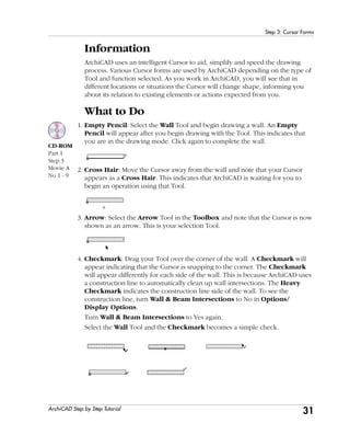
  • 35. 31 Step 3: Cursor Forms ArchiCAD Step by Step Tutorial Information ArchiCAD uses an intelligent Cursor to aid, simplify and speed the drawing process. Various Cursor forms are used by ArchiCAD depending on the type of Tool and function selected. As you work in ArchiCAD, you will see that in different locations or situations the Cursor will change shape, informing you about its relation to existing elements or actions expected from you. What to Do 1. Empty Pencil: Select the Wall Tool and begin drawing a wall. An Empty Pencil will appear after you begin drawing with the Tool. This indicates that you are in the drawing mode. Click again to complete the wall. 2. Cross Hair: Move the Cursor away from the wall and note that your Cursor appears as a Cross Hair. This indicates that ArchiCAD is waiting for you to begin an operation using that Tool. 3. Arrow: Select the Arrow Tool in the Toolbox and note that the Cursor is now shown as an arrow. This is your selection Tool. 4. Checkmark: Drag your Tool over the corner of the wall. A Checkmark will appear indicating that the Cursor is snapping to the corner. The Checkmark will appear differently for each side of the wall. This is because ArchiCAD uses a construction line to automatically clean up wall intersections. The Heavy Checkmark indicates the construction line side of the wall. To see the construction line, turn Wall & Beam Intersections to No in Options/ Display Options. Turn Wall & Beam Intersections to Yes again. Select the Wall Tool and the Checkmark becomes a simple check. CD-ROM Part 1 Step 3 Movie A No 1 - 9
  • 36. 32 Step 3: Cursor Forms ArchiCAD Step by Step Tutorial 5. Filled Pencil: Click again as indicated in the diagram and drag the Empty Pencil across the edge of the wall. Note the different Cursor forms that indicate which side of the wall is the active construction line. 6. Perpendicular Sign: Now drag the Striped Pencil to a point that appears perpendicular to the wall. The intelligent Cursor will indicate you are snapping to a perpendicular edge. 7. Striped Pencil: Now drag the Empty Pencil across the end of the wall. Note that on the end of the wall the pencil shows as filled. This is because a wall has a hot point at the four corners. 8. Intersection: Now draw a line crossing the other wall as shown. Drag your Cursor to the intersection of the two walls. The cursor changes to a Crosspoint, indicating that you are snapping to an intersection. 9. Mercedes Sign: Now put your Cursor alongside the edge of the wall. Notice how it changes to a Mercedes sign. This indicates that you are snapping to an edge. Note the different Cursor forms that indicate which side of the wall is the active construction line.
  • 37. 33 Step 3: Cursor Forms ArchiCAD Step by Step Tutorial 10. Tangent Sign: Select the Wall Tool and select the Center Arc geometry method from the Info Box. Draw a circular wall as shown. Now select the Single Wall option from the Info Box and draw a wall to a tangent of the circle as shown. The Cursor will change to a Tangent sign indicating you are snapping to the tangent edge. 11. Trident Sign: Click on the Marquee Tool in the Toolbox. Now draw a marquee window as shown. Notice that the Cursor changes to a Trident sign when placed over the marquee area. When the Trident appears, you can click and drag the marquee you have drawn and its contents. 12. Hammer: The Hammer is used to confirm an operation such as placing a dimension or a slab. To place a dimension, select the Dimension Tool, click your Cursor at both ends of the wall and then double-click. The Hammer will appear to place the dimension. 13. Magic Wand: The Magic Wand allows automatic operations such as wall tracing and creating fill boundaries. As an example, select the Wall Tool and select the rectangular geometry option from the Info Box. Draw a rectangular wall as shown. Now click on the Fill Tool, click the Magic Wand button from CD-ROM Part 1 Step 3 Movie B No 10 - 15
  • 38. 34 Step 3: Cursor Forms ArchiCAD Step by Step Tutorial the Control Box and click inside the box to place the fill. The Magic Wand is also available in the 3D Window. 14. Eyeball & Double Eyeball: The Eyeball and Double Eyeball indicates on which side to confirm an operation. Highlight the Door Tool and drag your Cursor to the edge of the wall until it turns into a Mercedes sign. Click on the wall edge and an Eyeball will appear. As you move the Eyeball, the insertion point of the door changes. The Double Eyeball locates the position of an edge-placed door or window. 15. Eyedropper/Syringe: This feature will automatically capture the settings and parameters from an object and allow you to draw with those settings or transfer the settings to another object. Using the door you just inserted, drag your Cursor to the edge of the door until you see a Checkmark. Now hold down the Option key (Mac) or Alt key (Windows). An Eyedropper will appear. Click on the door to capture its settings. Now draw another wall and place the door. Notice that the two doors are identical.
  • 39. 35 Step 3: Cursor Forms ArchiCAD Step by Step Tutorial Draw a new wall and insert a window in it with the default window settings. Next, double-click the Window Tool and change the window width. Click OK and place the window into the wall. Now capture the settings of the new window using the Option key (Mac) or Alt key (Windows) and the Eyedropper. Drag your Cursor to the first window you inserted and hold the Option and Command keys (Mac) or Alt and Ctrl keys (Windows) down. A Syringe Cursor form will appear. Click the edge of the window to transfer the window settings. 16. Markers for Half, Divisions, Percent & Distance: Turn on the Marker button on the Coordinates Box and select Half. Now drag your Cursor across the edge of the wall. A line marking the middle of the wall will appear. These are Hotspots on the wall that your Cursor can snap to. They are only temporary and will disappear after a few seconds. Repeat the above step to place a Marker for Divisions, Percent and Distance. 17. Cursor Alignment: ArchiCAD’s Cursor has a Rubberband Line that can align distant points and edges. This Rubberband Line has three modes: - Horizontal Alignment - Vertical Alignment - Angular Alignment To use these modes, click to start drawing a wall and hold down the Shift Key. This will invoke an automatic mouse alignment in either a vertical, horizontal or preset angle, which can be set in the Preferences. To use the Cursor CD-ROM Part 1 Step 3 Movie C No 16 - 20
  • 40. 36 Step 3: Cursor Forms ArchiCAD Step by Step Tutorial alignment, select one of the three choices from the Control Box while holding down the Shift Key. 18. Scissors: This form is used when trimming elements. The Black Scissors appear on top of elements that can be trimmed, while the White Scissors indicate that there is nothing to trim. To trim the wall, drag the Cursor to the edge of the wall while you hold down the Command key (Mac) or Control Key (Windows). The Black Scissors will appear. Now click on the wall. 19. Cloud: The Cloud represents the empty space over the horizon in perspective views. You cannot draw in this space of the 3D Window. 20. Context Menu: ArchiCAD’s Context Menu offers quick Menu commands specific to the item currently selected. To access this Menu, select the item and hold down the Control Key on Macintosh or use the Right Click mouse option on Windows.
  • 41. 37 Step 4: Editing and Notation ArchiCAD Step by Step Tutorial Step 4: Editing and Notation Overview In order to use productively the Tools we have learned, some key methods of editing and notation must be examined. This exercise will introduce these methods. Process to Learn • Editing Drawing Grid Setting Mouse Constraints Offset Controls Multiply Command Resize Command Stretch Command Explode Command • Notation Text Label Dimension • Find & Select Starting the Step To begin this step, double-click the file named Step-04.0.pln contained in the Step Files folder.
  • 42. 38 Step 4: Editing and Notation ArchiCAD Step by Step Tutorial What to Do 1. Drawing Grid: The Grid provides an easily adjustable and accurate Reference Grid on which to draw. The default is a horizontal and vertical grid system; however, the Grid can be rotated. • Set the Grid to the Default Orientation: In the Coordinate Box, make sure that the default horizontal/vertical grid is active by clicking on the appropriate button. The left button is the default Normal Grid. • Create a New Grid: Click on the Skewed Grid icon shown below. Immediately after clicking on the button, draw a line anywhere in the Floor Plan Window. When drawing the line, enter numeric angle information in the Coordinate Box if needed. The first click will define a new User Origin. 2. Setting Mouse Constraints: Constraining the mouse allows you to draw automatically at preset angles, such as 0, 90 and 45 degrees relative to the active Grid. • Edit Mouse Constraints: Go to Options/Preferences/Mouse Constraints & Methods. Here you can set which Grid is used as the active Grid. If you create a Skewed Grid, as in the previous exercise, here is where you indicate if you want your Cursor to react relative to the Skewed Grid or to the default Normal Grid when you draw your plan elements. 3. Offset Controls: ArchiCAD features the ability to create new lines, slabs, roofs, walls, beams and curves that are a controlled distance from the existing elements from which they are offset. You can make single or multiple offsets in one command. • Create a single Offset element: Draw or use a series of walls as shown in the file Step-04.0.pln. To offset these walls, select the Wall Tool and select the Single Offset button in the Control Box. Then click on the Magic Wand. CD-ROM Part 1 Step 4 Movie A
  • 43. 39 Step 4: Editing and Notation ArchiCAD Step by Step Tutorial Move the Magic Wand over to the walls. Click on the walls with the Magic Wand and drag the desired distance away from the walls. Click to finish. Select lines to offset. Select the Single Offset button, the Magic Wand and then click and drag on the lines. Double-click on desired spot to end. • Create Multi-Offset Elements: Creating multiple offset elements is almost identical to creating single offset elements. Follow the same steps as previously mentioned except in this case choose the Multiple Offset button. When dragging to offset, every click location will create a new element. Double-click to finish. Select lines to offset. Select the Multiple Offset button, the Magic Wand and then click to create copies. Double-click on desired spot to end. CD-ROM Part 1 Step 4 Movie B
  • 44. 40 Step 4: Editing and Notation ArchiCAD Step by Step Tutorial 4. Multiply: The Multiply command creates any number of exact copies of selected elements using the following options: - Drag multiplies the copies along a straight path defined by the reference line. - Rotate multiplies the copies along an arc, using the angle specified in the reference arc or numerically. - Elevate stacks the copies with a vertical displacement. - Matrix creates a group of columns and grids with the option of vertical displacement. • Multiply in One Direction Place and select column: Draw a column or double-click the file Step-04.1.pln in the folder named Step Files. Select the column with the Arrow Tool. Select Multiply... from the Edit Menu. In the Multiply dialog, select the Drag radio button from the Choose an action section. Enter 3 as the number of copies. Leave vertical displacement at zero. Select Distribute from the distribution choices. Click OK. • Drag copies: Click on the object and drag in any direction. Notice the ghosting of the copies that are created. Click to place your desired endpoint and to finish. • Multiply in Multiple Directions: Draw a column or use the opened file Step- 04.1.pln. Select the column with the Arrow Tool. Select Multiply from the Edit Menu. In the Multiply dialog, select the Matrix button from Choose an Action. Enter 4 copies Along First Stroke, 5 copies Along Second Stroke and leave vertical displacement at 0. Select Distribute from the distribution choices.
  • 45. 41 Step 4: Editing and Notation ArchiCAD Step by Step Tutorial • Drag Copies: Click on the column and drag the copies horizontally. Click to place the copies. Drag vertically to distribute the copies vertically. Click to finish Matrix. 5. Resize: The Resize… command allows you to select objects/elements and change their physical dimensions along with the spatial relationship. • Create Several Elements to Resize: Place several library objects, enter text, and draw a wall, similar to the diagram shown or double-click the file Step- 04.2.pln in the folder named Step Files. • Select Elements to Resize: Select the wall and a library part to resize. Access the Resize... command from the Edit Menu. Deselect Define Graphically and enter 150 into the percentage box. Make sure that both the Resize library parts and Resize wall, column thickness options are checked. Click OK and then click in the Floor Plan Window to complete the command. After resize, notice that affected items do not stay in the same location. CD-ROM Part 1 Step 4 Movie C
  • 46. 42 Step 4: Editing and Notation ArchiCAD Step by Step Tutorial • Select Elements to Resize Graphically: Select the same items from previous step. Access the Resize... command from the Edit Menu. Enable Define graphically. Make sure that both the Resize library parts and Resize wall, column thickness options are checked. Click OK and then click in the Floor Plan Window to select first resize reference point. Move the Cursor in a diagonal manner and click at second location to define second reference point. A rubberband boundary will appear indicating the increase or decrease in size. Click to finish. First boundary point Second boundary point Resize boundary Resize complete 6. Stretch: The Stretch command is used to stretch or shrink any selected ArchiCAD construction element (except the column). This command allows the endpoint of the selected element to be moved to a new position, stretching or shrinking the element, while the other endpoint remains at its original position. • Draw Several Construction Elements: Draw a wall, line and place an object or double-click the file Step-04.3.pln in the folder named Step Files. • Stretch Elements: Select the wall and then choose Stretch from the Menu. Click on the wall endpoint on its reference line side to move it to another location. A stretch vector will appear. Move the Cursor to the desired position, and click to finish. Repeat the Stretch commands with the other construction elements. CD-ROM Part 1 Step 4 Movie D No 6 - 7
  • 47. 43 Step 4: Editing and Notation ArchiCAD Step by Step Tutorial 7. Explode: The Explode command allows you to literally explode any complex construction element into basic ArchiCAD construction elements. Complex construction elements are: walls, library parts, windows and doors, columns, beams, slabs, roofs, stairs and dimensions. When exploded, these elements are automatically transformed into groups of lines, fills, curves or other basic elements. Once exploded they cannot be unexploded except by using the Undo command. • Draw Several Construction Elements: Draw a wall or double-click the file Step-04.3.pln in the folder named Step Files. • Explode the Elements: Select the wall and choose Explode from the Tools Menu. The wall is now a grouped set of basic elements. Go to the Tools Menu and select Suspend Groups. Now select a wall edge and delete it. The wall fill is now also an independent fill. Note that all 3D information is lost when an element is exploded. Repeat the Explode command for the other construction elements and see how they are broken down. Wall before exploding Wall after exploding Exploded elements ungrouped 8. Text: This sophisticated Tool offers multi-line texts, full-scale font options, multiple styles and justification in any direction. • Draw a Non-Breaking Text Block: To create a non-breaking text block, activate the Text Tool and then double-click on the worksheet where you want to type. The text line will continue until you stop typing or hit Enter to start a new line. • Draw a Breaking Text Block Area: To start a line of text, simply draw a rubberband rectangle by clicking twice with the Text Tool on the worksheet. A one-line block with the defined width remains on the screen, including a flashing text cursor indicating your position in the text block. • Type within the Text Block Area: Once the flashing text Cursor appears, you can start typing. Type until the words wrap and continue onto the next line. At any time, by hitting Enter, you can start a new line of text without letting the text block control the return.
  • 48. 44 Step 4: Editing and Notation ArchiCAD Step by Step Tutorial • Spell Check: The Spell Checker command in the Tools Menu allows you to check the spelling of your ArchiCAD project. The available features are quite similar to those used by Microsoft Word. Spell checking works on text blocks, zones, labels, custom text entered into dimension labels, as well as on door, window, object and lamp parameters. 9. Label: Labels are text blocks or symbols (special graphical objects pre-saved as ArchiCAD Label Files: *.lsm) optionally linked to construction elements, allowing you to identify or comment elements or parts of your design. Labels can be framed or unframed, with leader and arrowhead. The Label Settings dialog box gives you control over the orientation, typography and text of your label elements. The available labeling options allow you to label or unlabel manually selected elements, or to use automatic labeling for selected classes of construction elements. You can use two types of labels in ArchiCAD: • Independent Labels are manually placed and display custom text or symbol information. Draw Arrowhead and Leader of Independent Label: Click where you want the arrowhead to point on the floor plan. Draw a rubberband line from your starting point and click where you want the first section of your leader to end. Draw another rubberband line in the direction set by the Label Settings dialog box for the label handle. Clicking where you want the end of the handle will open the label text box automatically. Draw label leader Define extents with rubberband rectangle Type Label Text: Type the label text you desire in the text box and click the OK button or hit Enter to complete the operation. A label with the default settings will be placed.
  • 49. 45 Step 4: Editing and Notation ArchiCAD Step by Step Tutorial • Associative labels can be assigned automatically or placed manually. Optional label contents are text, ID, Internal ID or symbol. You can place an Associative Label manually, by clicking on an element with the Checkmark or the Mercedes Cursor while the Label Tool is active. 10. Dimension: The ArchiCAD Dimension Tool is a powerful and sophisticated feature that allows you to add customized dimension lines to your projects. When you modify dimensioned elements (for example, stretching a wall) the change is reflected in the dimension line and value. • Configure the Settings for the Dimension Tool: Open the Dimension Tool by double-clicking on its icon. Configure the settings. Make sure that the Linear setting is enabled. • Select Dimension Geometry: Select the Dimension Tool by clicking on its icon. Next select the Horizontal Geometry Method from the Info Box. • Select Dimension Points: Mark the first reference point by clicking on a wall node to start from. Click on each end node of the wall and window, then double-click to close the dimension chain. Hitting the Delete key once or pressing the OK button in the Control Box will also display the Hammer Cursor. Click the Hammer Cursor to place the dimension string. CD-ROM Part 1 Step 4 Movie E
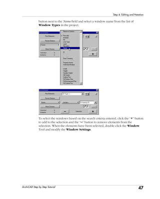
  • 50. 46 Step 4: Editing and Notation ArchiCAD Step by Step Tutorial 11. Find and Select: Find & Select command allows you to search for elements matching a virtually limitless combination of criteria. It is also possible to search for elements similar to the one that you select in your project, and save search criteria for future use. • Draw a Series of Walls and Windows: Draw a series of different walls and insert window types with different settings or double-click the file Step- 04.4.pln in the folder named Step Files. • Open Find & Select: Go to the Edit Menu and select the Find & Select command. Select Of Type >> from the Find Elements pop-up menu. Next, select the Window Type option in the Of Type >> pop-up menu. This defines the first criteria and defines the element type. The second criteria is to define the specifics of the Window Type. Click the More Choices button for more search options. Click the pop-up button (which currently shows Pencolor) and select Name. Next, click the pop-up CD-ROM Part 1 Step 4 Movie F
  • 51. 47 Step 4: Editing and Notation ArchiCAD Step by Step Tutorial button next to the Name field and select a window name from the list of Window Types in the project. To select the windows based on the search criteria entered, click the “+” button to add to the selection and the “–” button to remove elements from the selection. When the elements have been selected, double-click the Window Tool and modify the Window Settings.
  • 52. 48 Step 5: The 3D Environment ArchiCAD Step by Step Tutorial Step 5: The 3D Environment Overview The underlying principle of ArchiCAD is that a building is created on the computer not as lines but as a Virtual Building complete with 3D information. This step introduces how to view and edit the virtual model environment and the types of options available. You begin the lesson using the two basic methods of the 3D Settings: parallel projections and perspective settings. Process to Learn • 3D Settings Parallel Settings Perspective Settings • Marquee Selection Options • Interactive 3D Window Navigation • Editing in 3D Starting the Step To begin this step, double-click the file named Step-05.pln contained in the Step Files folder.
  • 53. 49 Step 5: The 3D Environment ArchiCAD Step by Step Tutorial 3D Settings 1. 3D Projection Settings: Before you display a 3D view or ask for a photorealistic rendering, you can choose from a number of view options in the 3D Projection Settings dialog box. There are two main dialog boxes for 3D views: Parallel Projection Settings and Perspective Settings. • Parallel Settings: With the Step-05.pln file open, choose the 3D Projection Settings dialog under the Image Menu. Using the dialog, try different parallel projections to view the model, such as axonometric, top, side and other view options as shown below. To change your viewpoint, drag the camera around the house and click OK. To change the sun position, drag the sun around the house and click OK. Parallel Projection Presets CD-ROM Part 1 Step 5 Movie A
  • 54. 50 Step 5: The 3D Environment ArchiCAD Step by Step Tutorial • Perspective Settings: Open the 3D Projection Settings dialog, under the Image Menu. Click the Perspective button at the top of the dialog and use the Perspective Settings dialog. To try different perspective views, drag the end of the camera and/or the focal point to a different position and click OK. 2. Marquee Tool: Use your Marquee Tool to highlight specific areas. The model will be clipped at the Marquee’s boundaries. The thin marquee images one floor and the thick marquee images all floors. • Marquee an Area: Select the Marquee Tool. Select an area of the plan and then view either a parallel or perspective projection to see the result. 3. Interactive 3D Window: The 3D Window allows for interactive 3D motion. Interactive navigation through your model is available in both Parallel and Perspective modes. The following steps will guide you through various options for determining position and movement in the 3D virtual environment. CD-ROM Part 1 Step 5 Movie B
  • 55. 51 Step 5: The 3D Environment ArchiCAD Step by Step Tutorial • Navigate the 3D Window - Parallel Projections: Go to the Image Menu, select 3D Projection Settings and create a Parallel Projection. Click on the Model Axis button and then select the Turn button in the 3D Navigation Palette. Place the Cursor on the 3D Window and click and drag the mouse slowly to the right. Drag the mouse to the left. Now try upwards and downwards. You are rotating the model about its axes. Click on the Target Lock button and then repeat the different rolling procedures. Notice the difference in the way the model rolls. Click the Frontal View button and then click on a surface you want to view in elevation. The view resets to the elevation of that element. CD-ROM Part 1 Step 5 Movie C
  • 56. 52 Step 5: The 3D Environment ArchiCAD Step by Step Tutorial • Navigate the 3D Window - Perspective Projections: Go to the Image Menu, select 3D Projection Settings and create a Perspective Projection. Click on the Camera button and then on the Walk button in the 3D Navigation Palette. Place the Cursor on the 3D Window with the Cursor Arrow facing up and drag the mouse slowly upward to walk forward; drag the mouse down to walk backwards, and to the right or left to walk to the side. Try using the Turn button and the Lateral Move Tool . Notice the difference in movement. Click on the Target Lock button and repeat the previous Tool selections and maneuvers. Select the View Cone Angle to slide the button right or left to change the view cone angle, which affects the current zoom. 4. Editing in 3D: The 3D Window also allows for editing and creating elements interactively in 3D. The editing can be accomplished in the Parallel Projection or Perspective Projection dialogs. The methods for either dialogs are the same, but simpler viewing is an advantage in the Parallel Projection CD-ROM Part 1 Step 5 Movie D
  • 57. 53 Step 5: The 3D Environment ArchiCAD Step by Step Tutorial dialog. The following steps will demonstrate simple 3D editing in the Parallel Projection dialog box. • Create a Parallel Projection to Edit: Use the Parallel Projection from the previous step. - Click on the Edit Mode button in the 3D Navigation Palette to enable 3D editing. This allows you to select elements in the 3D Window, similar to the Floor Plan Window function. - Click on the Sensitive Cursor switch in the 3D Navigation Palette. This enables the Cursor to snap to any element node. If this is off, the Cursor will only snap to nodes in the current reference plane. - Click on the Pointer Lines switch next to the Sensitive Cursor switch. This links the coordinate axes and the Cursor with dotted lines. This is a very helpful Tool that allows you to see the spatial location of the Cursor on screen when you are editing or creating elements. - Move the Cursor over several wall nodes to see the results. • Select a Wall and Suspend Groups: Walls are automatically grouped together as you draw. This allows you to select all the walls by clicking on an individual wall. To edit an individual wall, you must ungroup or suspend the group. To do this, click on the face or node of a wall to select all the walls. Then turn on Suspend Groups from the Tools Menu or select the Suspend Groups button from the Control Box. • Select a Wall to Edit: Click on the face or node of a wall. The wall nodes will be highlighted indicating that the wall is selected. CD-ROM Part 1 Step 5 Movie E
  • 58. 54 Step 5: The 3D Environment ArchiCAD Step by Step Tutorial • Stretch the Wall: Click and hold the Cursor on a wall node. A Context Menu appears. Here you can select various functions to apply to the selected wall. Select the Vertical Stretch option and move your cursor down the wall. A dashed ghost preview of your stretch effect is displayed as you move the Cursor. Release the cursor at the location shown Updated 3D Window view • The Modified Wall: Once you click your Cursor to end the Stretch operation, the 3D Window automatically updates itself. After the update, you can see how the 3D edit appears. 5. More 3D Editing: Other elements can also be edited in the 3D Window. In fact, almost all operations from the Floor Plan Window can be done in the 3D Window. • Now that you have tried editing a wall in 3D, try editing the window or dragging a copy of the window in 3D.
  • 59. 55 Step 6: Understanding Libraries ArchiCAD Step by Step Tutorial Step 6: Understanding Libraries Overview ArchiCAD is an object based program. This step introduces the concept of element types stored in outside files, including doors, windows, lamps, labels, and general objects. These objects can be stored in an ArchiCAD Library, a project library or over the Internet. This exercise introduces the concept of a referenced library and how to change, add and delete libraries from your project file. Process to Learn • What are Objects Types of Objects Purpose of Objects Object Parameters • Starting with the ArchiCAD Library • Loading a Project Library • Loading an Internet Library Starting the Step To begin this step, double-click the file named Step-06.pln contained in the Step Files folder.
  • 60. 56 Step 6: Understanding Libraries ArchiCAD Step by Step Tutorial Information Library Parts are parametric prefabricated complex elements created either by ArchiCAD or a third party application and used as units in projects. When you start ArchiCAD for the very first time, it searches for a Library under the name ArchiCAD Library. The icons in the Toolbox that reference ArchiCAD Libraries are as follows: What to Do 1. View an Object Library: To review the Object Library and how it is organized, double-click the Object Tool in the Toolbox. The Object Settings dialog will appear. The Object Settings dialog (shown below) is similar for all library parts which includes windows, doors, lamps, objects and stairs. The dialog contains a library part browser at the top and a system explorer tree to the left. You can choose different views.
  • 61. 57 Step 6: Understanding Libraries ArchiCAD Step by Step Tutorial CD-ROM Part 1 Step 6 Movie A 2. Review the Loaded Libraries: When ArchiCAD opens a project, it loads one or more libraries from the local hard drive, network or the Internet. To review which libraries that are currently loaded, open Library Manager from the File Menu. • Local/LAN: The Local/LAN tab page allows you to manage complete libraries and individual library parts stored on local disks or on remote volumes connected to your computer through a local area network. Click on the Local/LAN tab and the currently loaded ArchiCAD Libraries will appear in the dialog. • FTP and Web Objects: - Using the FTP Sites tab page, you can add libraries and single library parts stored on FTP servers. - The Web Objects tab page allows you to download GDL Objects from websites and add them to your local libraries. Since you are currently working from your local hard drive, the FTP Site and Web Object Settings will be empty since no links have been established to an online site.
  • 62. 58 Step 6: Understanding Libraries ArchiCAD Step by Step Tutorial 3. Understanding the Status Report: If a Library Part within your project has not been loaded, you will receive a status message like this: If this happens, simply open your Library Manager by either clicking the Library Manager... button in the bottom left corner of the Status Report or by choosing the Library Manager command from the File Menu, then browse and add the missing library part to the active libraries.
  • 63. 59 Step 7: Option Settings ArchiCAD Step by Step Tutorial PART TWO: PROJECT & OFFICE SETUP 7. OPTION SETTINGS 8. DRAWING PREFERENCES 9. LAYER ORGANIZATION 10. QUICKVIEWS AND FAVORITES
  • 64. 60 Step 7: Option Settings ArchiCAD Step by Step Tutorial Step 7: Option Settings Overview We can customize options such as line types, pens, colors, fills, composites and zones to our specific project needs. Note: If you only have a demo version of ArchiCAD, you will not be able to do this exercise as described here, because copying is not available in the demo version. Process to Learn • Pens & Colors • Line Types • Fill Types • Composites Starting the Step Open the file named Step-07.pln contained in the Step Files folder.
  • 65. 61 Step 7: Option Settings ArchiCAD Step by Step Tutorial What to Do The document just opened will be used as the basis for much of the remaining tutorial. Each step will build upon the model to create a Virtual Building from which to derive plans, sections, elevations, renderings, virtual reality scenes and more. Using the controls in the Options Menu, you can set up and customize ArchiCAD to reflect your office standards and preferences. 1. Pens & Colors: ArchiCAD pen and color assignments are reviewed and modified using the Pens & Colors… command. In ArchiCAD, pens are simulated drawing instruments that have a specific color and line weight. • Create Custom Pens and Colors: Open the Pens & Colors... dialog from the Options Menu. Place your Cursor in a square within the selection box and then drag it around the squares. Notice that the pen number and Pen Weight change with each pen color. Highlight a pen color and double-click the square. A Color Picker dialog will appear allowing you to customize the pen color. (The Color Picker dialogs differ on Windows and Macintosh systems.)
  • 66. 62 Step 7: Option Settings ArchiCAD Step by Step Tutorial 2. Line Types: When you choose the Line Types… command, a dialog box appears allowing you to select, modify or delete the standard line types (solid, dotted, dashed, etc.). You can also define your own customized line or symbol line types. • Create a Custom Line Type: Open the Line Types... dialog from the Options Menu. Click New and enter the name Small Dashed. Click OK. Enter the numeric values Dash - .05 and Gap - .05, or manually change the line type spacing by selecting and dragging a flag. • Create a Custom Symbol Line Type: Draw a simple group of elements using the Line Tool. Select all the elements and copy the elements using the Copy command. Open the Line Types... dialog from the Options Menu. Click New and select Symbol. Type in the name of the new line type. Click OK. Click on Paste line components. Enter the numeric values or manually change the Symbol line spacing and scale by selecting and dragging a flag. CD-ROM Part 2 Step 7 Movie A
  • 67. 63 Step 7: Option Settings ArchiCAD Step by Step Tutorial 3. Fill Types: Fills are geometric patterns that can display two faces: bitmapped and vectorial, but only one of the two at one time. You can set this option in Display Options. • Create a Custom Fill Pattern: Draw three lines as shown. Select the lines and copy them using Copy in the Edit Menu. Select Fill Types... from the Options Menu. Click on New, select Symbol Fill, and type in a name. Click OK and then click Paste. The elements you pasted create a new Fill Pattern. Edit the Bitmap pattern by clicking in the Bitmapped Pattern box to create black or white pixels. An exact preview of the pattern is not necessary in the box area. CD-ROM Part 2 Step 7 Movie B
  • 68. 64 Step 7: Option Settings ArchiCAD Step by Step Tutorial 4. Composite Structures: Both walls and slabs can have composite structures. Columns have separate fills for their Cores and their Veneers. • Create a Custom Composite Wall: Open the Composites... dialog from the Options Menu. Select Site Wall 08", duplicate and name it Wood Stud Wall. Click OK. Highlight Concrete Structural and change to T & G Gypsum Coneboard with 1/2" thickness. Add new skin with the Add button. Skin name _2x6 Wd.Studs@12"oc.Spr.No.2, Skin thickness 6". After this add a new Skin with the same preferences. Note: Both Fill Types and Composite Structures can be shown with either Bitmap or Vectorial patterns in the Display Options. Bitmap Patterns are faster to display but cannot be scaled, zoomed or rotated, while Vectorial Patterns are slower to display but can be scaled, zoomed and rotated. CD-ROM Part 2 Step 7 Movie C
  • 69. 65 Step 8: Drawing Preferences ArchiCAD Step by Step Tutorial Step 8: Drawing Preferences Overview This step demonstrates how to define the preferences for the project. Drawing preferences can range from setting the types of measurements used on a project to the sensitivity of the cursor. This exercise will show how to set these preferences to meet your specific project and user needs. Process to Learn • Set Drawing Preferences Working Units and Dimensions Calculation Units and Mouse Constraints Construction Elements and Zones Imaging and Data Safety • Shortcut Key Settings • Set Drawing Scale Starting the Step Use your file from the previous step or open the file named Step-08.pln contained in the Step Files folder.
  • 70. 66 Step 8: Drawing Preferences ArchiCAD Step by Step Tutorial What to Do 1. Set the Drawing Preferences: Before a drawing or model is started, it is important to set up the standard settings for the project. To set the preferences, go to the Options Menu and select Preferences. The pop-up menu at the bottom of the command lists the available options. For the purpose of this exercise, review these options and set them to reflect your preferences. • Working Units and Dimensions: Go to the Working Units. Click Next to set the Dimensions, which provide a mechanism for customizing and storing different Dimensioning Standards. This is useful for working on several projects with differing levels of accuracy (construction details versus site plans) or projects being built in countries other than those in which they are designed.
  • 71. 67 Step 8: Drawing Preferences ArchiCAD Step by Step Tutorial • Calculation Units and Mouse Constraints: The Calculation Units dialog allows you to set the units to use in quantity calculations. The settings you make here will affect text format lists. The Mouse Constraints & Methods dialog provides control over the angle pairs used for mouse constraint with the Shift key and the sensitivity of the Cursor. • Construction Elements and Zones: Construction Elements preferences allow you to set the default for the line type depicting the outline of slab or roof above or below a story as well as to set the general preferences for 3D Intersection Priorities. The Zones screen contains controls for defining the behavior of Related Constructions when creating zone lists. The top part of the dialog box concerns recesses cut in walls by door and window openings; the Wall & Column Subtraction area defines whether walls and columns can be included or excluded from the zone’s size; and the low Ceiling Reductions specifies to what degree reduced height spaces will be taken into account when calculating zone sizes.
  • 72. 68 Step 8: Drawing Preferences ArchiCAD Step by Step Tutorial • Imaging and Data Safety: The Imaging & Calculation dialog provides options for rebuilding the 3D Window, monitoring rendering progress, creating reports and dealing with error alerts. The Data Safety dialog contains a number of features to minimize the risk of data loss and file corruption. This is especially important if your power lines suffer from voltage spikes or failures, or if your computer is prone to software conflicts. • Web Options and Miscellaneous: The Web Options dialog contains a number of controls related to Internet and HTML formatting. The Miscellaneous dialog contains preferences for a variety of features, including multiplatform save, default colors and generic dialog box options. 2. Shortcut Keys: This command allows you to define your own shortcuts to each Menu command. To view the shortcut key preferences, select Menu Shortcut Keys from Preferences in the Options Menu.
  • 73. 69 Step 8: Drawing Preferences ArchiCAD Step by Step Tutorial To create a custom shortcut, choose a menu name from the pop-up list, then select a command from the Commands list. You can create a shortcut to the selected item by defining a character combination on the right side of the dialog box. Confirm the defined shortcut by clicking the Assign button. If you don’t need the selected shortcut anymore, click Detach. 3. Setting the Drawing Scale: Traditional concepts of architectural scale (for example 1/4" =1') become important only when you are creating a scaled hard copy of your project, or exporting the project into either PlotMaker or bitmap picture formats for post-processing in another application. The scaled dimensional size of the drawing does not change if you rescale your document. Only the relative size of fixed (or paper) size elements like text or vectorial hatch patterns changes, as compared to the construction elements (walls, objects, slabs, etc.), which have been defined in world coordinates. These fixed size elements stay at a fixed scale, independent of the working drawing scale. • After setting a scale, what you see will be a preview of the project if printed or plotted at that scale. To see a real preview, not a zoomed one, choose Actual Size in the Display Menu after setting the scale. Note: If you change the drawing scale, the current view will change accordingly, and the current magnification will remain constant. To return to the previous view of the window, choose the Previous View command in the Diplay Menu.
  • 74. 70 Step 8: Drawing Preferences ArchiCAD Step by Step Tutorial Create a plan with some construction elements, dimensioning and labeling: To set the scale of your document, activate the Floor Plan Scale under the Options Menu or click the scale icon in the workspace. In the Scale dialog box specify the scale as 1/8'' = 1'-0''. Change the Scale to 1/2''=1'-0''. Notice that the 4 pt. text and arrowhead remain the same point size. The construction elements have changed in size relative to the fixed size elements, but they still scale correctly at 1/2'' scale.
  • 75. 71 Step 9: Layer Organization ArchiCAD Step by Step Tutorial Step 9: Layer Organization Overview This step is the foundation that manages all the plans, sections, elevations and 3D information for your Virtual Building. ArchiCAD manages this information by using layers to turn information on or off. As you draw an element in ArchiCAD, the element is automatically assigned a layer. Process to Learn • Layer Settings Layer Modification Layer Combinations • Project Standards • Setting Up for Plans • Setting Up for Sections/Elevations • Setting Up for the 3D Environment • Grids & Backgrounds Starting the Step Use your file from the previous step or open the file named Step-09.pln contained in the Step Files folder.
  • 76. 72 Step 9: Layer Organization ArchiCAD Step by Step Tutorial What to Do 1. Layer Settings: ArchiCAD layers are used to organize the elements in your drawing for selective displays and quantity calculations. The Layer Settings… command displays the Layer Settings dialog box which allows you to define the layer settings for your project. The currently defined layers for your project are displayed in the scrollable list on the left side of the dialog box. To select a layer, click it so that it appears highlighted. • Modify Layers: Open the Layer Settings dialog under the Options Menu. Select all Layers except the Mark-Up and the Hidden Mark-Up Layer and click the Clear button. This provides a clean slate to add layers that are project specific. Next, select each Layer Combination individually and click the Clear button. CD-ROM Part 2 Step 9 Movie A
  • 77. 73 Step 9: Layer Organization ArchiCAD Step by Step Tutorial Using the Layer Settings dialog as shown, create new layers by selecting New and typing the name of the new layer. Enter the layers from the Project Layer List as shown below. Project Layer List Appliances Landscaping Building Slabs Lamps Ceiling Fills Plumbing Ceiling Lights Roof Ceiling Slabs Sections Columns Site Plan Text Dimensions Site Slabs Elevations Site Terrain Floor Plan Text Stairs Framing Walls - Exterior Framing Plan Text Walls - Interior Furniture Zones Furniture Plan Text Once the layers have been entered, create project layer combinations. To do this, type in the layer combination name and click Add. Once all the layer combinations are entered, select Show or Hide layers for each layer combination as shown. After a layer change, Modify the layer combination to update the layer combination. Enter the Layer Combinations from the Project Layer Combination Setup as shown below:
  • 78. 74 Step 9: Layer Organization ArchiCAD Step by Step Tutorial Project Layer Combination Setup Ceiling Plan - Select these Layers to Show Ceiling Fills, Ceiling Lights, Ceiling Slabs, Columns, Sections, Walls-Exterior and Walls-Interior Floor Plan - Select these Layers to Show Appliances, Columns, Dimensions, Elevations, Floor Plan Text, Plumbing, Sections, Stairs, Walls-Exterior, Walls-Interior and Zones Framing Plan - Select these Layers to Show Building Slabs, Columns, Framing, Framing Plan Text, Sections, Walls- Exterior and Walls-Interior Furniture Plan - Select these Layers to Show Appliances, Columns, Furniture, Furniture Plan Text, Lamps, Plumbing, Sections, Stairs, Walls-Exterior and Walls-Interior Site Plan - Select these Layers to Show Landscaping, Roof, Sections, Site Plan Text, Site Terrain 3D Model - Select these Layers to Show Appliances, Building Slabs, Ceiling Lights, Ceiling Slabs, Columns, Elevations, Framing, Furniture, Lamps, Landscaping, Plumbing, Roof, Sections, Site Terrain, Stairs, Walls-Exterior, Walls-Interior and Zones The layer combinations generally reflect the drawings that are to be produced (such as floor plan, ceiling plan and furniture plan). It is also necessary to create a 3D model layer combination that turns on all 3D information for sections, elevations and visualization. For example, you may want to turn on an overhead cabinet for a section or perspective view, but turn it off for the floor plan. When finished, click OK. A Warning will appear informing you that you have deleted layers and asking if you wish to confirm this. Click Proceed. Note: Default layers are assigned to each tool as a default setting. If the layers are deleted the connection will terminate. After having created the above layer combinations you can choose between them under Option/Layers.
  • 79. 75 Step 9: Layer Organization ArchiCAD Step by Step Tutorial 2. Grids & Background: The Grids & Background dialog allows you to define a working grid configuration as well as establish a background color for your workplace. • Create a Project Grid: Set the Main Grid to 2' and the Snap Grid to a spacing of 1". Background controls the color of the 2D worksheet itself. Double-clicking the background color will open the Edit Color sub-dialog box. You can select your color graphically or numerically by mixing the HSL (Hue–Saturation– Lightness) or RGB (Red–Green–Blue) components. The Grid lines color control works in the same way as the Background. A color for the construction grid can be selected for the grid lines themselves.
  • 80. 76 Step 10: QuickViews and Favorites ArchiCAD Step by Step Tutorial Step 10: QuickViews and Favorites Overview In Step 10 you will learn how to use QuickViews and Favorites to set up project views, display options, scale and layers as well as how to save default tool settings and settings of previously selected elements. The QuickViews Palette is generally used to establish the settings for drawing sheets such as the Floor Plan, Ceiling Plan, Electrical Plan, etc. The Favorites Palette can create office standards by saving the default settings for drawing symbols, wall types, window types, roof assemblies, etc. Process to Learn • QuickViews Types of QuickViews Using a QuickView Save Current View Redefine View • Favorites Understanding Favorites Creating Favorites Selecting a Favorite Starting the Step To begin this step, double-click the file named Step-10.pln contained in the Step Files folder.
  • 81. 77 Step 10: QuickViews and Favorites ArchiCAD Step by Step Tutorial What to Do 1. QuickViews Palette: There are two types of quickviews, QuickViews for floor plans, sections and elevations and 3D QuickViews for perspectives and parallel projections. The QuickViews Palettes allow you to move around, save and publish different preset and user-defined views at various zoom levels and locations. • Go to QuickViews: Open the file Step-10. pln and click the QuickViews Palette in the upper right-hand side of your screen. If the Palette is not there, go to the Window Menu, select Floating Palettes and Show QuickViews, or click on QuickViews in the display bar at the bottom of the Floor Plan Window. • Create New Views: Fit your drawing to the entire ArchiCAD Window by choosing Fit in Window from the Display Menu. Notice the small Overview Area in your QuickViews Palette. Now zoom in tightly on part of the drawing by selecting Zoom In from the Display Menu and then selecting the area to enlarge on your floor plan. Maybe you will need to choose Redraw All OverViews from the QuickViews Menu. Notice how the gray square updates in the QuickView according to what portion of the drawing appears on your screen. These views can be saved by clicking on the triangle in the upper right corner and selecting Save Current View. When you are done, the new view should be listed in the scrollable list. CD-ROM Part 2 Step 10 Movie A
  • 82. 78 Step 10: QuickViews and Favorites ArchiCAD Step by Step Tutorial • Go to 3D QuickViews: Go to the 3D Window and if the 3D QuickViews Palette does not appear, go to the Window Menu, select Floating Palettes and Show 3D QuickViews. • Create New 3D Views: To create 3D QuickViews, you can either use the Image Menu commands or the Camera Tool to place one or several perspective or VR cameras. Axonometric views defined in the 3D Projection Settings dialog box are also available. When the image is generated, you can save a 3D QuickView by clicking the pop-up button in the top right corner of the Palette.
  • 83. 79 Step 10: QuickViews and Favorites ArchiCAD Step by Step Tutorial A pop-up menu appears, listing a number of commands. The list is somewhat shorter than for 2D views. If you choose Save Current View… a dialog box is displayed as for 2D views with a number of options specific to 3D views. 2. Favorites Palette: The Favorites Floating Palette allows you to save and easily recall default tool settings and settings of previously selected elements. • Go to Favorites: To access this palette, choose Window/Floating Palettes/ Show Favorites. The Palette appears and remains visible on top of the other Windows, like the QuickViews Palette. • Creating Favorites: You can save Favorites with the pop-up control on the top right of the Palette. You can add to the Favorites the currently active tool’s default settings by choosing Save Current Default Settings… in the pop-up menu on the top right. Enter a name in the dialog box that appears. Note: This command has no effect if the Arrow or the Marquee Tool is active in the Toolbox. • Select another tool and repeat the steps. • Selecting a Favorite: On top of the Palette, you can choose with a small pop- up control the amount of detail to display. CD-ROM Part 2 Step 10 Movie B
  • 84. 80 Step 10: QuickViews and Favorites ArchiCAD Step by Step Tutorial Select one of the wall types you created. To set the Wall Tool to your selected favorite, click the Set button. The Wall Tool is now set, draw the wall and the default is your selected favorite.
  • 85. 81 Step 11: Building Slab ArchiCAD Step by Step Tutorial PART THREE: CREATING A VIRTUAL BUILDING 11. BUILDING SLAB 12. WALLS AND COLUMNS 13. DOORS AND WINDOWS 14. STAIRS AND HANDRAILS 15. ROOF PLAN 16. BUILDING STRUCTURE 17. FURNITURE AND EQUIPMENT 18. CEILINGS AND LIGHTS 19. MOLDINGS AND PANELS 20. ZONES AND SECTION/ELEVATION 21. SITE LAYOUT 22. CREATING LIBRARY PARTS
  • 86. 82 Step 11: Building Slab ArchiCAD Step by Step Tutorial Step 11: Building Slab Overview This step will teach you how to use the Slab Tool for creating floor assemblies and how to use the slab as a modeling tool. You will explore various ways of manipulating slab shapes and slab openings. Process to Learn • Slab Tool Creating a Slab Displaying Slab Outline Slab Materials • Editing a Slab Editing a Node Setting Materials Starting the Step Use your file from the previous step or open the file named Step-11.pln contained in the Step Files folder.
  • 87. 83 Step 11: Building Slab ArchiCAD Step by Step Tutorial What to Do 1. Slabs: Slabs are the basic horizontal building blocks in ArchiCAD. Slabs are drawn on the Floor Plan as polygons, allowing them to accommodate any design. Existing slabs are easily modified on the floor plan or through the Slab Settings dialog box. In this exercise we will create a building slab as shown below. This slab will become the foundation for creating walls and footings. • Select the 3D Model Layer Combination: To set the 3D model workspace that will turn on the Building Slab layer, select the 3D Model layer combination from the Options/Layers/Layer Settings dialog box. • Edit Slab Settings: Double click the Slab Tool and set the slab settings to the information as shown below. First set the Floor Plan and Section Attributes and then the Model Attributes:
  • 88. 84 Step 11: Building Slab ArchiCAD Step by Step Tutorial Slab thickness: 1'-0'' and Slab elevation: 0'-0'' to Project Zero Slab Section Attribute: Concrete Structural Slab layer: Building Slabs Slab material: Wood-Flooring strip • Draw the Slab: With the slab settings configured, go to the Info Box and select the polygon slab geometry option. In the Coordinate Box, click the triangle so that it is depressed. This turns on Relative Coordinates, which means that the Origin begins at x=0 and y=0 each time a drafting or editing process is under way. Click on the Project Origin and begin drawing a slab. First select the Y key to highlight the Y field in the Coordinate Box. Enter 24'-0" for Y and 0 for X. To confirm the slab dimension, use the Enter key. Continue drawing the remaining slab points with the Coordinate Box as previously described. CD-ROM Part 3 Step 11 Movie A
  • 89. 85 Step 11: Building Slab ArchiCAD Step by Step Tutorial Complete the remaining points on the slab based on the following dimensions. 18' 7' Project Origin 13'-0" 3'-0" 9'-0" 13'-0" 3'-0" 24'-0" 18'-0" 38'-0" 38'-0" 18'-0"7'-0" • Create a Curve in the Slab: To draw a curve in the slab we must add two points to the slab and then extrude a curve from the edge of the slab. First go to the Toolbox and select the Arrow Tool. With the Arrow Tool selected, click the edge of the slab so that it is highlighted. Next, go to the Control Box and set the Distance where the first point of the slab will start, which will be from the upper right corner of the rectangular slab you just created. Place the Cursor over the edge of the slab to get a distance CD-ROM Part 3 Step 11 Movie B
  • 90. 86 Step 11: Building Slab ArchiCAD Step by Step Tutorial mark and click where the distance mark appears. Then click again to confirm the new slab point. Now repeat the above exercise and add a second point as shown below. Finally, click in-between the two points you have added to the slab and choose the Curve from the Pet Palette that appears. Enter the radius, 5'-8", in the Coordinate Box and confirm with the Return key.
  • 91. 87 Step 11: Building Slab ArchiCAD Step by Step Tutorial The final slab will look like this:
  • 92. 88 Step 12: Walls and Columns ArchiCAD Step by Step Tutorial Step 12: Walls and Columns Overview In this step, you will learn how to build, move and shape Wall and Column elements. It will teach you how to apply dimensions to walls and columns as well as how to use the coordinate system. Process to Learn • Wall Tool Wall Settings Dialog Box Wall Construction Types Wall Reference Lines and Intersections • Column Tool • Dimension Tool Starting the Step Use your file from the previous step or open the file named Step-12.pln contained in the Step Files folder.
  • 93. 89 Step 12: Walls and Columns ArchiCAD Step by Step Tutorial What to Do 1. Layer Combination: Layer combinations allow us to set our workplace to the appropriate plan type, such as the Floor Plan, Ceiling Plan, Furniture Plan or 3D Model. • Select the Floor Plan Layer Combination: To set the Floor Plan workspace, select the Floor Plan layer combination from the Options/Layers/Layer Settings dialog box. 2. Walls: The wall is a fundamental element in the practice of architecture. When you create a wall in ArchiCAD, you create the outline and hatching of a wall in 2D, a solid wall body in 3D and the wall properties. • Edit Wall Settings for Exterior Walls: Double-click the Wall Tool and set the exterior wall settings to the information as shown below. First, set the Floor Plan and Section Attributes and then the Model Attributes. Select the layer Walls-Exterior for the layer setting for exterior walls. Exterior wall height: 9'-0" Exterior wall width: 9 1/2" Exterior wall composite: Brick Veneer + 2x4 Wd Stud @16" O.C. Wall material - Exterior : Ext-Brick New Wall material - Interior : Surface-Whitewash
  • 94. 90 Step 12: Walls and Columns ArchiCAD Step by Step Tutorial • Create the Exterior Walls: Walls can be created two ways, either by drawing each wall point by point, similar to the way the slabs were created, or by extruding the walls from the slab. First, set the reference line of the wall to the exterior edge. To do this, select the right reference line option from the Info Box. Then turn the Wall & Beam Intersections to Yes in the Options/Display Options dialog box. To extrude the walls, select the Magic Wand and click on the edge of the slab. The walls will automatically trace the outline of the slab. The extruded walls will appear as in the following plan. • Edit Wall Settings for Interior Walls: Double-click the Wall Tool and set the interior wall settings to the information as shown below. Select the Layer Walls - Interior for the layer setting for the interior walls. Interior wall height: 7'-10" Interior wall width: 4 1/2" CD-ROM Part 3 Step 12 Movie A
  • 95. 91 Step 12: Walls and Columns ArchiCAD Step by Step Tutorial Interior wall fill pattern: Gypsum Board Wall material: Surface-Whitewash • Create the Interior Walls: Select the single wall geometry option from the Info Box. Drag the Cursor to the corner of the exterior wall and click. Then drag the Cursor to the opposite wall corner and click. 3. Columns: The Column is a Tool for easy definition of columnar structures. All elements created with the Column Tool are either rectangular or circular and can stand free or be connected to walls. • Place a Column: Open the Column Settings dialog by double-clicking on the Column Tool, and then set the column to 6" x 6" x 7'-10". Set the Floor Plan & Section Attributes and then the Modes Attributes as shown below. Select the insertion point to upper right and place a column at the corner of the wall. Place the Column to the Columns Layer. CD-ROM Part 3 Step 12 Movie B
  • 96. 92 Step 12: Walls and Columns ArchiCAD Step by Step Tutorial Column Core Attributes: Wood Column Materia: Wood - Pine • Multiply the Columns: Click the Arrow Tool, select the column and choose Multiply from the Edit Menu. In the Multiply dialog select Matrix, and set 3 copies along the first stroke and 1 copy along the second stroke. Select the Distribute option. Click OK. Click the column corner, drag the 3 copies to the wall corner and click. Now enter 3'-0" for the X coordinate to complete the second stroke and hit Enter. 4. Dimensions: ArchiCAD provides various options for dimensioning: Semi- Automatic, Fully Associative and Various Measurement Units and Standards. • Add Dimensions to the Plan: Open the Dimension Tool by double-clicking on its icon. Select the layer Dimensions for the layer setting and set the text size and the Witness Line Type as shown below. CD-ROM Part 3 Step 12 Movie C
  • 97. 93 Step 12: Walls and Columns ArchiCAD Step by Step Tutorial Next, select the Horizontal Geometry Method from the Info Box palette. Mark the first dimension reference point by clicking on a wall node. Click on each end node of the wall, then double-click to close the dimension chain. Hitting the Delete key once or pressing the OK button in the Control Box will also display the Hammer Cursor. Place the dimension string by clicking the Hammer Cursor at the desired location. Finish adding dimensions as described on the following floor plan. Remember to change the direction of the dimension (vertical, horizontal and angle) by choosing it from the Info Box.
  • 98. 94 Step 13: Doors and Windows ArchiCAD Step by Step Tutorial Step 13: Doors and Windows Overview In Step 13, you will learn about the Door and Window Tools, which create realistic architectural openings in wall elements by inserting special library parts with editable parameters. Because the Door and Window Tools behave almost identically, we will often refer to them as the Door/Window Tool unless a specific difference needs to be mentioned. Process to Learn • Door Tool • Window Tool • Parameters for Doors/Windows • Using the ArchiCAD Library • Placing a Door/Window • Viewing a Door/Window • Creating a New Story • Copying Elements between Stories Starting the Step Use your file from the previous step or open the file named Step-13.pln contained in the Step Files folder.
  • 99. 95 Step 13: Doors and Windows ArchiCAD Step by Step Tutorial Lower Story What to Do 1. Doors and Windows: Both windows and doors are Library Parts, meaning you can select any library folder and load its contents for further use. All the Library Parts in loaded libraries are available for the current project. Windows and doors can only be added by placing them into an existing wall. CD-ROM Part 3 Step 13 Movie A
  • 100. 96 Step 13: Doors and Windows ArchiCAD Step by Step Tutorial • Edit Door Settings: Double-click the Door Tool and select a door object from the ArchiCAD Library 70. The door’s location in the ArchiCAD Library 70 is shown above. Configure the appropriate door dimensions and information. Click OK. To set the leaf style, click the fifth button in the Door Settings dialog box. Scroll through the list and select the style you would like to use.
  • 101. 97 Step 13: Doors and Windows ArchiCAD Step by Step Tutorial • Place Doors: The Info Box allows you to select either Edge, Sill or Reveal for your method of construction. You also select to place a door according to its center or edge. Select the appropriate settings. In the Control Box select the distance marker from the pop-up menu. Set the distance to 2'. Move the Cursor over the edge of the wall. Click on the distance marker that appears. Click once to start door placement then move your Cursor to indicate the inside face of the door and also the swing direction. Click again. • Place Windows: Placing windows involves steps very similar to choosing and selecting doors. Refer to the steps in the door exercise for window settings and placement.
  • 102. 98 Step 13: Doors and Windows ArchiCAD Step by Step Tutorial • Place a Corner Window: ArchiCAD will automatically cut both sides of a corner wall when you place a corner window. To place a corner window, double-click the Window Tool and select a corner window. Then click on the corner point of the wall and then click on the inner or outer side of the wall. Place a Corner Window with the settings shown in the picture above. Note: The same window is placed in both of the walls, if we want to modify the windows one by one, the Corner Window Function checkbox should be turned off. With this the windows are editable as singly. CD-ROM Part 3 Step 13 Movie B
  • 103. 99 Step 13: Doors and Windows ArchiCAD Step by Step Tutorial 2. Story Settings: Choosing the Stories in the Options Menu opens a sub-menu with commands that allow you to: - Define the vertical structure of your design, story by story - Navigate between stories by determining which story is currently displayed - Move elements and items between them using a special Cut, Copy and Paste All Story functions are controlled through the Stories sub-menu. The Stories defined in the Story Settings… dialog box are displayed at the bottom of the sub-menu. The current Story is shown with a check mark in the listing and the name appears in the title bar of the Floor Plan Window function. • Create an Upper Story: Open the Story Settings dialog box under the Options Menu. Click in the Name text box and enter Lower Story. Next, click Insert Above and enter Upper Story in the Label text box. Enter 9' for the Height to Next floor. Now highlight the Lower Story again and click the Column and Slab icons within the Edit Elements of Selected Story. This will allow us to copy all elements from the Lower Story except for columns and slabs. Click the Copy All button and then highlight the Upper Story and click the Paste Selected Types button and click OK. The Upper Story is now created. To move between floors, go to the Options Menu, Stories and select the floor you wish to go to. CD-ROM Part 3 Step 13 Movie C
  • 104. 100 Step 13: Doors and Windows ArchiCAD Step by Step Tutorial 3. Ghost Story: The Ghost Story will display every element located on another story behind the one that you’re currently working on. Ghost story elements can be snapped to and their settings can be viewed or copied, but can only be edited on their home story. You can either display a given story or the one directly above or below the current one. • Go to the Upper Story: To move to the Upper Story, select Stories from the Options Menu and select 1. Story. • Turn on the Ghost Story: To view the Ghost Story, select the Show Ghost Story from Stories in the Option Menu or turn it on in the Stories dialog. Drag your Cursor to an element on the Ghost Story. You will notice that the Cursor snaps to it but a warning message appears if it is selected, indicating that is inactive since it is on the floor below. You can also choose to view the story above or below your current story. 4. Edit the Upper Story: Now edit the walls, doors and windows to reflect the design needs for the upper story. Select the 3D Model Layer Combination. • Delete Curved Wall: Since the curved wall is not required on the Upper Floor, select the Arrow Tool and click on the curved wall to highlight it. Then hit the Delete key to erase it.
  • 105. 101 Step 13: Doors and Windows ArchiCAD Step by Step Tutorial • Edit and Extend the Wall: First click the upper wall with the Arrow Tool and highlight it. Now hit the delete key and erase it. Next, select the remaining lower wall and highlight it. Select the Stretch command from the Edit Menu, click on the outside edge of the wall and drag your Cursor to stretch the wall. Now stretch the wall to the outside point of the opposite wall. Select the entrance door previously copied from one story lower, delete it, then place a glass wall in its place with the same settings as of the opposite wall. Select and delete the Gypsum interior wall, then stretch the main wall as shown below. Then draw a new Gypsum interior wall.
  • 106. 102 Step 13: Doors and Windows ArchiCAD Step by Step Tutorial • Edit the Wall Heights: The exterior walls around the Master Bedroom need to be increased in height for the barrel vault roof. To do this select the four walls, then open the Wall Settings by clicking the Wall button in the Info Box. Set the height of the walls to 11'-0". • Edit the Doors and Window: Change the doors and windows to reflect the design for the Upper Story plan. Refer to the directions in the previous part of this step for placement of windows and doors.
  • 107. 103 Step 14: Stair and Handrails ArchiCAD Step by Step Tutorial Step 14: Stairs and Handrails Overview This step will teach you how to create a custom stair using the Stair Tool. StairMaker lets you easily design and construct all kinds of stairs required for ArchiCAD projects by selecting from a set of predefined geometry types, or by drawing the main geometry of the stair and editing parameters. Process to Learn • Stair Tool Creating a Stair Object Selecting the Stair Type Setting Flight and Tread Defining the Stair Structure Selecting the Handrail • Handrail Object Editing a Handrail Placing a Handrail Starting the Step Use your file from the previous step or open the file named Step-14.pln contained in the Step Files folder.
  • 108. 104 Step 14: Stair and Handrails ArchiCAD Step by Step Tutorial What to Do 1. Create a Second Floor Slab: Before adding the stair we must add the Second Floor slab. • Edit Slab Settings: Go to the Upper Story. Double click the Slab Tool and set the slab settings to the information as shown below. First set the Floor Plan and Section Attributes and then the Model Attributes: Slab thickness: 1'-0'' and Slab elevation: 0'-0'' to Project Zero: 9' Slab Section Attribute: Wood 45 Slab layer: Floors Choose One Story Down from the list as shown below. Slab material: Wood-Flooring Strip • Draw the Slab: With the slab settings configured, go to the Info Box and select the slab geometry continuous slab option.
  • 109. 105 Step 14: Stair and Handrails ArchiCAD Step by Step Tutorial To create the slab, click the Cursor on the inside edge of the walls. To finish, click on the first point again or click the OK button in the Control Box. 2. Stair Object: You can create stairs using two different methods: - Using the Stair Tool - Using the prefabricated stair objects stored in the ArchiCAD Library. The Stair Tool (an external object tool) is used to place and edit Stair Object library parts into the project, which add a floor plan symbol to the plan, appear in Sections/Elevations, 3D visualizations and appear in quantity calculations. The Stair is created by selecting a stair type from the Stair Type Selection dialog. • Set the Stair Settings: Open the Stair Tool dialog and select Create New Stair from the pop-up menu. Select a straight run stair type with no landing from the Stair Type Selection dialog and double-click to edit the stair settings. CD-ROM Part 3 Step 14 Movie A
  • 110. 106 Step 14: Stair and Handrails ArchiCAD Step by Step Tutorial The dialog opens to the settings for Geometry, Flight and Tread. In the Geometry Settings, edit the stair size as shown. Then select the stair to structure connection button as shown below. Click the Stair Structure button to set the settings for Structure, Attributes and Landing. Set the Structure to a closed stair type and material Attributes describing the stair structure to Wood-Oak. Next, click the Tread Settings button and set the material finish for the treads. Select the Attribute finish as Wood-Oak. Finally, click the Railing button to set the type of stair railing, location of the railing, newel settings and any additional parameters. For this stair, select the Solid Frame with Balustrade from the pop-up Railing Setting. In the preview, you can select the location of the railing and then you can give its type. Set the railing to be on the left side. When finished, click the OK button. A Save as dialog will appear. Save the new stair to your ArchiCAD Library 70/Object Library 70 folder as House Stair.esm.
  • 111. 107 Step 14: Stair and Handrails ArchiCAD Step by Step Tutorial The stair will appear in the Stair Settings dialog. Now set the stair settings for the insertion point and parameter settings for the 2D drawing. First, click the stair parameter for Dashed Lines Above Break to turn it on. Next, set the layer to Stairs and click OK. Finally, rotate the stair by dragging your Cursor inside the stair preview window until the Cursor changes to a rotate symbol. Click your Cursor to rotate the stair as shown. Next, click the corner of the stair where the stair will be inserted. A box will appear marking that corner as the insertion point for the plan. Finally click OK. • Insert the Stair: Now that the stair has been selected and the parameters have been set, we need to place it on our plan. To do this, go to the Lower Story plan by selecting Stories from the Options Menu. Now move the Cursor to the corner of the window where the stair will be placed. This is the corner where the stair insertion point was defined in the Stair Settings dialog. Click to place the stair into the plan.
  • 112. 108 Step 14: Stair and Handrails ArchiCAD Step by Step Tutorial • Now let's see the other method: Select the Stairs Straight Run 70 element as shown below. Set the parameter values as shown in the picture, then place the element on the Floor Plan. Switch on the Show One Story Up checkbox. Note: This object will be used throughout the rest of the tutorial. 3. Handrail Object: The Object Tool is used to place and edit library parts that include handrails. This will add a floor plan symbol to the plan, appear in Sections/Elevations and 3D visualizations and appear in quantity calculations. • Edit Handrail Object: To edit the Handrail Object, double-click the Object Tool and select Rail Balustrade 70 from the Object Library as shown. CD-ROM Part 3 Step 14 Movie B
  • 113. 109 Step 14: Stair and Handrails ArchiCAD Step by Step Tutorial Set the parameters as shown below. Set the materials to Wood-Oak. Next, select the Stairs layer and click the upper right corner of the handrail to mark the insertion point. Click OK. • Place Handrail Object: Before placing the handrail, select the Diagonal geometry method from the Info Box. This will allow you to insert the object and stretch it to the final length. To place the handrail, drag the Cursor to the edge of the stair and click. Now drag the Cursor to the point where the handrail will end and click. Repeat this for the remaining handrails.
  • 114. 110 Step 15: Roof Plan ArchiCAD Step by Step Tutorial Step 15: Roof Plan Overview In this Step, you’ll explore the basic techniques used to create roofs by building several roof geometry types using the Roof Tool. Process to Learn • Roof Tool Slope Direction and Pivot Lines Types of Roofs PolyRoof Domed Roof Vaulted Roof Pitched Roof Controls • Displaying Roof Outline • Trim Walls and Columns to Roof • Creating a Roof in the 3D Window • Placing Skylights and Dormers Starting the Step Use your file from the previous step or open the file named Step-15.pln contained in the Step Files folder.
  • 115. 111 Step 15: Roof Plan ArchiCAD Step by Step Tutorial Lower Story Roof Plan Dome Roof What to Do 1. Dome Roof: A Dome Roof is created using the Roof Tool. The number of strips and segments that make up the dome can be defined in the Dome Settings dialog box. Once the dome is created, its parts can be edited as individual pitched roofs, but not as a whole. • Edit Roof Settings: Double-click the Roof Tool and set the roof settings. First set the Floor Plan and Section Attributes. CD-ROM Part 3 Step 15 Movie A
  • 116. 112 Step 15: Roof Plan ArchiCAD Step by Step Tutorial Next, set the Materials for the roof in the Model Attributes. Set the current layer to the Roof Layer. • Define the Dome Roof Outline: With the Roof Tool selected, select the Dome Roof in the Info Box. With the first click, you define the center of the Dome, the second click marks the beginning and the third click defines the end of the outline. • Edit the Dome Settings: Once you have defined the outline, the Dome Settings dialog box appears. Edit the settings for the dome as shown below.
  • 117. 113 Step 15: Roof Plan ArchiCAD Step by Step Tutorial Upper Story Roof Plan Barrel Vault Roof Pitched Roof 2. Pitched Roof: By choosing the PolyRoof geometry method, you can create equally sloped roofs on any polygonal or curved base. • Select the Polyroof Geometry Method: With the Roof Tool selected, select the Polyroof in the Info Box. • Draw the Pitched Roof Outline: Draw the roof axis point by point along the exterior edge of the wall. When you complete the roof, a PolyRoof Settings dialog appears. CD-ROM Part 3 Step 15 Movie B
  • 118. 114 Step 15: Roof Plan ArchiCAD Step by Step Tutorial Now enter the roof settings into the PolyRoof Settings dialog box. Set the Eave Overhang to 1'-0", set the Roof Thickness to 4", the roof height to 9'-0" and the pitch to 5/12. The thickness represents both the roof framing and the roofing system. Click OK to create the roof. • Change Hip to Gable Roof: Select the Arrow Tool and select the pitched roof you created. To ungroup the roof, select Ungroup from the Tools Menu. Select the Hip roof to be deleted and hit the Delete key. Now click the Roof Tool, select the edge of the roof and stretch the ridge to meet the edge of the wall as shown. Repeat for the opposite Gable roof. Trim the Wall Tops to the Roof. Select all the walls under the new roofs and go to the Edit Menu. Select the Trim to Roof command and check Trim Top. Click Trim.
  • 119. 115 Step 15: Roof Plan ArchiCAD Step by Step Tutorial 3. Barrel Vaulted Roof: This method allows you to model any form of a roof structure, including the most complex ones. In this exercise, we will model a simple Barrel Vaulted Roof in the 3D Window. • Create a 3D Parallel Projection: Select 3D Projection Settings from the Image Menu. Create a parallel project similar to the following view. • Create the Barrel Vault Roof in 3D: Click the Roof Tool, select the Edit Mode button from the 3D Navigation Palette and select the Barrel Vaulted geometry method from the Info Box. First open the Magic Wand Settings from the Tools Menu and change the Deviation from Curves to 1" from 2". Note: Clean Wall & Beam Intersections must be turned ON in order to create a Barrel Vaulted Roof in 3D. Drag the Cursor to the corner of the wall where the Barrel Vaulted roof will begin. Click and drag the Cursor to define the width of the Barrel Vault. Click at the wall corner and a Pet Palette will appear with three editing options. Select the Curved Barrel Vaulted option. CD-ROM Part 3 Step 15 Movie C
  • 120. 116 Step 15: Roof Plan ArchiCAD Step by Step Tutorial To accurately define the height of the roof, first you have to change the height system to User Origin, and after this enter 3'-0" into the Coordinate Box and hit the Enter Key. Now define the length of the Barrel Vaulted Roof by dragging the Cursor the length of the building and clicking on the wall corner to finish. • Trim Roof in 3D: The next step is to connect the wall with the Barrel Vaulted Roof. To do this we need to extend the wall and trim it to the roof. Select the Arrow Tool and click the wall as indicated below at left. Double click the Wall Tool and change the wall height to 15'-0" to extend it beyond the roof. With the wall selected, choose the Trim to Roof command from the Edit Menu. Select Trim Top in the appearing dialog . Click the Trim button to trim the wall. Rotate around the model and repeat the same procedure with the opposite wall.
  • 121. 117 Step 15: Roof Plan ArchiCAD Step by Step Tutorial 4. Placing Skylights and Dormers: Smart skylights are objects that can be intelligently placed within a roof. The skylight object placed on top of a roof will be automatically inserted in the roof and adjusted to the correct roof slope angle, at the appropriate elevation, rotated to the correct angle (parallel with the roof’s reference line) and a hole will automatically be cut in the roof. • Place the Skylight: Skylight objects are stored in the Dormers and Skylights folder of the standard ArchiCAD Library. Double-click the Object Tool and select Skylight Top Hung from ArchiCAD Library 70. The Skylight’s location in the ArchiCAD Library is shown below. Set the parameters values as shown in the picture. Set the Current layer to Roof. To place the skylight, you must have a roof. You can insert the skylight object in it in either 2D or 3D. In the Floor Plan Window, you place the skylight inside the outline of the roof. In the 3D Window, click on the roof plane. ArchiCAD will detect the location of the mouse-click and place the skylight on the roof plane. You can place the Skylight object to the other roofs by using the multiply command. First select the Skylight object in the Floor Plan Window and after this open the Edit Menu and select the Multiply command. CD-ROM Part 3 Step 15 Movie D
  • 122. 118 Step 15: Roof Plan ArchiCAD Step by Step Tutorial If you open the 3D Window then you will see the Skylights are placed to the roof.
  • 123. 119 Step 16: Building Structure ArchiCAD Step by Step Tutorial Step 16: Building Structure Overview This step will teach you to build, move and edit beams and roof framing elements. The Beam Tool creates straight, horizontal construction elements of rectangular profile. You will see how you can generate Truss elements with TrussMaker. Process to Learn • Footings • Beam Tool Beam Settings Placing a Beam Editing Beams • TrussMaker Creating Trusses Truss Profile Starting the Step Use your file from the previous step or open the file named Step-16.pln contained in the Step Files folder.
  • 124. 120 Step 16: Building Structure ArchiCAD Step by Step Tutorial What to Do 1. Structural Footing: The Slab Accessories command places the Footing with Stem wall object, which can model a concrete footing with stem wall and sill plate. • Select the Lower Level Slab: The Slab Accessories command uses the slab as an outline for creating the footing. To select the slab, go to the Lower Level by selecting the level from the Stories menu option. Next, select the Slab which is situated under the perimeter of the building. The slab will be highlighted by dots at each point on the slab indicating that the slab is selected. Now go to the Extras Menu and select Slab Accessories from the Accessories command. • Set the Parameters: The Object Settings dialog box is where you can select the xs7-footing object. If you select this then the Interface of the object will appear. This contains two pages, on the first page you can set the plate type, stem wall and footing dimensions, on the second page you will find the parameters for the section attributes. Change the dimensions as required and then click the OK button. Place the object to the Building Slabs layer as shown below. Note: The parametric object section fills will only be valid if you check the Use Symbol Section Attributes checkbox in the Section Attributes tab page. CD-ROM Part 3 Step 16 Movie A
  • 125. 121 Step 16: Building Structure ArchiCAD Step by Step Tutorial 2. Beam Tool: The Beam Tool creates straight, horizontal construction elements of rectangular profile. Beams interact with one another, and with construction elements. Beams can be drawn on the Floor Plan or in the 3D Window and can accommodate holes. In this exercise we will create the floor framing for the Upper Story. • Select the Framing Plan Layer Combination: To set the Framing Plan workspace, select the Framing Plan layer combination from Layers in the Options Menu. • Go to the Upper Story: To move to the Upper Story, select Stories from the Options Menu and select Upper Story. • Edit Beam Settings: Double-click the Beam Tool and set the Beam Settings. First, set the information for the Floor Plan and Section Attributes. Give the Beam a dashed line type and select Wood as the Section Attribute. Set the Beam size to 10" x 2" and the top of the framing to 8'-10". Set the materials to Pine for all sides of the Beam and select the Framing layer. CD-ROM Part 3 Step 16 Movie B
  • 126. 122 Step 16: Building Structure ArchiCAD Step by Step Tutorial • Create Floor Framing: Select the Distance Marker option in the Coordinate Box and enter 1'-4". Drag the Cursor to the inside edge of the wall. Markers will appear on the wall. With the Beam Tool selected, click on the marker and drag the Cursor to the opposite wall until you see a Checkmark Cursor form, then click to finish your first beam. Select the Arrow Tool, click on the beam to highlight it and select Multiply from the Edit Menu. Choose Spread, enter 1'-4" for spacing and click OK. Now click the edge of the beam to highlight it and drag the Cursor to the corner at the opposite side of the bedroom.
  • 127. 123 Step 16: Building Structure ArchiCAD Step by Step Tutorial • Edit Beam Settings: Double-click the Beam Tool and set the Beam Settings. Set the Beam size as 1'-0" x 6" and the top of the framing to 8'-10". • Create Beams: With the Beam Tool selected, click on the middle of the edge of the column and stretch the beam to the next column. Repeat this for each of the columns. When finished, fill in the floor framing similar to the previous exercise. • Create Beam Under the Wall. Edit Beam Settings: Double-click the Beam Tool and set the Beam Settings. Set the Beam size as 1'-2" x 9 1/2" and the top of the Beam to 9'.
  • 128. 124 Step 16: Building Structure ArchiCAD Step by Step Tutorial Set the materials to Surface-Whitewash for all sides of the Beam and select the Wall-Exterior Layer. Place the Beam as shown below. 3. TrussMaker: TrussMaker allows you to create girder and truss objects for visualization purposes. When properly installed, the TrussMaker hierarchical menu appears in ArchiCAD’s Extras Menu. • Create a Truss Outline: Scroll over to an empty space on your Floor Plan. Open the Line Settings and set the pen color to pen 1/black. Select the Line Tool and select the Single Line option. Click on the Floor Plan and enter the length of the line using the Coordinate Box, 12'-1" in the X coordinate and 0' in the Y coordinate. Now press Enter. Open the Pen Color Palette again and change the pen color to pen 9/ Magenta. Now draw a vertical line for the truss. Select the Half mark from the Control Box and click to start the line, then enter 2'-8 9/32" for the Y coordinate and press Enter. CD-ROM Part 3 Step 16 Movie C
  • 129. 125 Step 16: Building Structure ArchiCAD Step by Step Tutorial Open the Circle/Arc Tool and set the pen color to pen 1/black. Next, select the Circle Tool and select the 3 point geometry method from the Info Box. Click the end of the horizontal line to start, then click the top end of the vertical line and click the other end of the horizontal line to finish the curve. Finally, select the Line Tool again and add several additional support lines to the truss as shown. Note: During the Truss creation you can assign sections to pen colors. • Select TrussMaker: To create the truss object from the outline you created, select all the lines you created. To do this, select the Arrow Tool and click once on one side of the truss and drag your Cursor across the lines you created. When the Cursor crosses all of the lines, click a second time to select the lines. Now go to the Extras menu and select Create Truss from TrussMaker. • Set the Parameters: The Object Settings dialog will appear displaying options for timber construction, hollow section and rolled steel. Select the Timber Construction option and click on the Attributes tab. Enter 11' for the height of the truss. Set the material to Wood-Pine, and set the layer to Roof Layer as shown below.
  • 130. 126 Step 16: Building Structure ArchiCAD Step by Step Tutorial Next, click the Truss Profiles tab and set the parameters as shown below. When finished, click Save and save to your hard drive, to the ArchiCAD Library 70. After this an object will appear on the 2D plan. Select the Arrow Tool and click on the corner of the truss to select it. Then select Drag from the Edit Menu, click on the edge of the truss and drag it to the column as shown in plan. Finally, select the Multiply command from the Edit Menu, define 3 copies and choose Distribute. Click at the corner of the truss, drag to the opposite wall and click to finish.
  • 131. 127 Step 17: Furniture and Equipment ArchiCAD Step by Step Tutorial Step 17: Furniture and Equipment Overview In this Lesson, we explore placing, editing and creating furniture and equipment with the Object Tool. This connects you to the ArchiCAD Object Library. In Step 22, we will learn how to create custom 2D and 3D library parts that can be added to your project library. Process to Learn • Object Tool Placing Objects Rotating Objects Multiplying Objects Stretching Objects • The ArchiCAD Library Starting the Step Use your file from the previous step or open the file named Step-17.pln contained in the Step Files folder.
  • 132. 128 Step 17: Furniture and Equipment ArchiCAD Step by Step Tutorial Lower Story Furniture Plan What to Do 1. Objects: The Object Tool is used to place and edit library parts within the project, which add a floor plan symbol to the plan, appear in Sections/ Elevations and 3D visualizations (if they have a 3D description) and appear in quantity calculations. ArchiCAD Library objects range from furniture and bathroom appliances to any building block that you may find easier to define this way than with other Tools in ArchiCAD, such as balustrades, special chimneys, etc. The available objects reside in the current ArchiCAD Library. Object library parts consist of: • A 2D graphic symbol representing the object on the floor plan • A 3D shape appearing in Sections/Elevations and 3D images described in a GDL (Geometric Description Language) script • A Properties definition, describing the object and its components • Go to the Lower Story. To move to the Lower Story, select Stories from the Options Menu and select Lower Story. Switch off Show Ghost Story. To do this, select Show Ghost Story from Stories in the Options Menu.
  • 133. 129 Step 17: Furniture and Equipment ArchiCAD Step by Step Tutorial • Set the Plan to the Furniture Plan Layer Combination: To set the working environment to the Furniture Plan, select the Furniture Plan layer combination in Options/Layers/Layer Settings. • Select Furniture and Equipment: Open the Object Settings dialog and select the object from within the ArchiCAD Library as shown: • Set the Drawing Information: Next change the object parameter information to reflect the drawing information required for the object. • Select Layer: Select the appropriate layer for each library part: Furniture objects are placed on the Furniture layer Plumbing objects are placed on the Plumbing layer Appliance objects are placed on the Appliances layer
  • 134. 130 Step 17: Furniture and Equipment ArchiCAD Step by Step Tutorial • Set Background Fill for Plan Symbol: Objects can display a graphic fill in the Floor Plan Window. Click the Plan Symbol line in the Parameters box to reveal the plan parameters. If you want to choose another fill, highlight the Background Fill Pen and choose color. After this, highlight the Background Fill Type and click the pop-up symbol to view the Fills. Now we will use the default settings. • Select Insertion Point and Rotate: Objects can be placed, selected, and fitted to other elements by using object hotspots. Object hotspots are defined in the 2D symbol of the library part. This hotspot is marked with a highlighted rectangle whenever the object appears in the Object Settings dialog box. To rotate the object, drag the Cursor over the object. When the Cursor changes to a Rotate Cursor form, click the Cursor to rotate the object.
  • 135. 131 Step 17: Furniture and Equipment ArchiCAD Step by Step Tutorial • Place the Object: To position an object, click on the desired position in the floor plan. The insertion point will be stored as the anchor point. You can use numerical input, gravity, rulers or the grids to assist you in positioning objects accurately. This allows you to fit fixtures or furniture to corners, specific positions, or to each other with great accuracy. Fitting an object to a specific position (a chair to a table, for instance) is further helped by the object’s hotspots because the Cursor is sensitive to these points. 2. Multiply Objects: Objects can be multiplied using the Multiply command. In this exercise, place the table and then place a chair. Select the chair with the Arrow Tool and choose Multiply from the Edit Menu. Next, set the Multiply action to Rotate, the number of copies to 3 and select Increment. When finished, click OK. Move the Cursor to the center of the table. A Checkmark will appear. Click on the center to mark the center of the rotation. Move the Cursor to the center of the chair and click to mark the edge of the rotation. Now move the Cursor to the right and three copies of the chair will appear. Move to the point where the second chair is to be placed and click. CD-ROM Part 3 Step 17 Movie B CD-ROM Part 3 Step 17 Movie A
  • 136. 132 Step 17: Furniture and Equipment ArchiCAD Step by Step Tutorial 3. Stretching Objects: To stretch an object, select the object with the Arrow Tool, choose Stretch from the menu or click on the edge of the object and hold the mouse button down. Now pull away from the object to stretch it. 4. Place More Objects: Once you are finished with the Lower Story Furniture plan, select Stories from the Options Menu and select the Upper Story. Place the upper story furniture and plumbing fixtures using the same steps as described in the previous exercise. Use the upper story plan shown below for location and object names. Upper Story Furniture Plan
  • 137. 133 Step 18: Ceilings and Lights ArchiCAD Step by Step Tutorial Step 18: Ceilings and Lights Overview In this Lesson, we explore placing, editing and creating a 3D ceiling, a 2D ceiling pattern and ceiling lights using the Slab Tool, Fill Tool and Lamp Tool. Ceiling lights are 3D objects, so when placed on a ceiling, they become both a 2D graphical element as well as an element containing light. Process to Learn • Lamp Tool • Fill Tool • Creating Ceiling Grids • Fill Origin Link to Project Origin Link to Fill Origin Display Options • 2D and 3D Ceilings Starting the Step Use your file from the previous step or open the file named Step-18.pln contained in the Step Files folder.
  • 138. 134 Step 18: Ceilings and Lights ArchiCAD Step by Step Tutorial What to Do Ceilings are created in 3D using the Slab or Roof Tool. The 3D ceiling, however, does not create a 2D representation for the Ceiling Plan. Therefore, we must also place a Fill pattern to indicate the ceiling for the reflected ceiling plan. This exercise describes how to create and place the ceiling fill pattern and the associated light objects. Switch off the Grid Display, to do this click Grid Display in the Options Menu. 1. Set the Plan to the Ceiling Plan Layer Combination: Layer combinations allow us to set our workspace to the appropriate plan type, such as the Ceiling Plan, Floor Plan and Furniture Plan. To set the working environment to the Ceiling Plan, select the Ceiling Plan layer combination from Options/Layer/ Layer Settings. 2. Fill Patterns: Fills are geometric patterns that have three view options: solid, bitmapped and vectorial. In a project, all fills are displayed either as bitmapped or vectorial. You can change this option under Display Options command in the Options Menu. • Change Fill Display from Bitmap Pattern to Vectorial Hatching for exact ceiling grid representation. • Create a New Fill Pattern for the Ceiling: Follow the steps in Step 7 for creating Custom Fill Patterns, but in this case, create a 2' square, copy it, and create a new 2' x 2' Grid Fill as shown below. First, Draw a 2' square with the Line Tool, select the lines and choose Copy from the Edit Menu. CD-ROM Part 3 Step 18 Movie A
  • 139. 135 Step 18: Ceilings and Lights ArchiCAD Step by Step Tutorial Create a new 2' x 2' Ceiling Grid Symbol Fill as shown in Step 7. • Draw the New Fill Pattern for the Ceiling: Double-click the Fill Tool and select the 2' x 2' Grid from the pop-up Fill Settings. Select the Ceiling Fills layer and click OK. To place the fill, click the Magic Wand and click the Cursor inside the Kitchen boundary.
  • 140. 136 Step 18: Ceilings and Lights ArchiCAD Step by Step Tutorial • Defining the Grid Start Point: Each fill has a Fill Handle that determines the location of the fill start point and the angle. To adjust the fill, click the Arrow Tool, select the edge of the fill and open the Fill Settings. Change the fill to Link to Fill Origin in the dialog and click OK. With the fill highlighted, click the X at the center of the fill and drag the Cursor to relocate the Fill Origin. • Draw the Gypsum Board Ceiling: Open the Fill Settings and select Gypsum Board from the fill pop-up selection. Change the fill method to Link to Project Origin. Select the Poly Fill geometry method and draw the ceiling over the entry as shown. 3. Lower Story Lights: The Lamp Tool is used to place additional light sources as library parts into the project. Most of the Lamp Tool’s settings, features and techniques are identical to those of the Object Tool. The additional Lamp controls affecting their behavior in PhotoRenderings are found in the middle part of the Lamp Settings dialog box. You can set the light source’s color by double- clicking the Light Color box. The switch next to the light color control allows CD-ROM Part 3 Step 18 Movie B
  • 141. 137 Step 18: Ceilings and Lights ArchiCAD Step by Step Tutorial you to define whether the given lamp will be lit or not in the PhotoRendering. The brightness of the light can be set either with a sliding switch, or by entering a number between zero and 100 in the box next to the switch. • Select a Light: Open the Lamp Tool, select lights from the ArchiCAD library, and select the Lamps or Ceiling Lights layer as required. • Set the Lamp Object Information: Next change the Lamp Object parameter information to reflect the drawing information required for the object. Remember to set the height of Lights as you edit the Lamp Settings. • Turn OFF Show Light Cone: The parameter Show Light Cone should be turned off for each light inserted. This feature shows the extent of light in elevations and in the 3D Window but will not be required for this exercise. • Place the Strip Lamps and the Recessed Spot Lamps to the Ceiling Lights Layer. The other types of Lamps should be placed on the Lamps Layer. After you finished to place the ceiling Lamps, set the Layer combination to Furniture Plan.
  • 142. 138 Step 18: Ceilings and Lights ArchiCAD Step by Step Tutorial • Place the Lights: Click on the desired light location. 4. Draw a 3D Ceiling with the Slab Tool: Now that we have created a 2D representation of the ceiling for the Ceiling Plan, let’s create a 3D Ceiling using the Slab Tool. To do this, open the Slab Tool and set the Model Attributes to Whitewash and the slab thickness to 1/2". for the Living Room for the Kitchen Set the slab layer to Ceiling Slabs. Close the dialog and select the rectangular geometry method. Draw the 3D ceiling for the Kitchen. After drawing the Kitchen, hold down the Space bar (activate the Magic Wand) and click to the edge of the Gypsum Board Fill to create the ceiling for the Living Room. CD-ROM Part 3 Step 18 Movie C
  • 143. 139 Step 18: Ceilings and Lights ArchiCAD Step by Step Tutorial 5. Display Options - Changing Door Swings to show Headers: Under the Options menu, click Display Options and change the Doors & Windows toggle button from Show on Plan to Reflected Ceiling. 6. Upper Story Lights: Add lights following steps similar to those used on the Lower Story. Be aware that vertical height placement of lights needs to correspond to the varying roof/ceiling heights. 7. Use Display Options under the Options Menu to change back to Show on Plan.
  • 144. 140 Step 19: Moldings and Panels ArchiCAD Step by Step Tutorial Step 19: Moldings and Panels Overview With the Wall Accessories command, you can place a variety of objects that add details to your walls including different types of moldings, wall panels and wainscot options. This exercise will also describe how to add these details to your walls and how to customize the profiles of moldings and trim. Process to Learn • Wall Accessories Command Interior Moldings Panel Details Creating Trim Profiles Parametric Options Starting the Step To begin this step, double-click the file named Step-19.pln contained in the Step Files folder.
  • 145. 141 Step 19: Moldings and Panels ArchiCAD Step by Step Tutorial What to Do 1. Select the Walls: ArchiCAD applies moldings and panels to selected walls. In this exercise we will apply wall panels with molding to the Kitchen walls. To do this, select the Arrow Tool. To select multiple walls, hold down the Shift key while selecting individual walls. Select each of the four Kitchen walls clicking on the inside of each wall. 2. Apply the Molding and Panels: Now that the walls have been selected, go to the Extras Menu and select Wall Accessories from the Accessories Menu. In the Object Settings dialog box select the Moldings and Panels object and set the Section Attributes to the type of molding profiles you would like to use. CD-ROM Part 3 Step 19 Movie A
  • 146. 142 Step 19: Moldings and Panels ArchiCAD Step by Step Tutorial On the Section Attributes page of the User Interface you can choose the type of the moldings. Set the parameters as shown below. Set the Layer to Furniture Layer. Once finished, click the OK button. The Eyeball icon will appear as your Cursor. Click within the inside of the Kitchen walls. ArchiCAD will build the panels around the room. Set the Plan to the 3D Model Layer Combination.
  • 147. 143 Step 19: Moldings and Panels ArchiCAD Step by Step Tutorial Select 3D Projection Settings from the Image Menu and choose Perspective Settings. Set the parameters as shown below. The final panel system will look similar to the image below.
  • 148. 144 Step 20: Site Layout ArchiCAD Step by Step Tutorial Step 20: Site Layout Overview This step will demonstrate several techniques for creating a site. Both the Slab Tool and the Mesh Tool can be used to create a site plan. Additionally, we will also learn how to use the Spline Tool to create topographic lines and transform them into a mesh. Process to Learn • Spline Tool Natural Spline Bézier Spline Freehand Spline • Figure Tool • Converting Splines to Mesh • Tools for Creating a Site Slab Tool Mesh Tool • Level Dimension Tool • Gravity Tool Starting the Step Use your file from the previous step or open the file named Step-20.pln contained in the Step Files folder.
  • 149. 145 Step 20: Site Layout ArchiCAD Step by Step Tutorial Information • Natural Spline method: This type of curve is defined by placing nodes, which the program automatically connects, thereby generating a smooth custom curve. The angle of the tangent and the shape of the spline generated with it is affected by each subsequent node defined. • Bézier Spline method: These type of curves are more complex in nature, but they allow more accurate reproduction of specific custom shapes. Bézier Splines are defined by nodes, just like Natural Splines, but they also have editable tangent handles on each side of these points. The shape of the Bézier Spline is affected by the direction of the tangent, and the length of each tangent handle. • The Freehand geometry method allows you to draw freehand curves. This is particularly useful to mark up documents. When you start marking up, ArchiCAD automatically activates the Spline Tool with the Freehand geometry method. Selected Splines can be converted from one type to another by clicking the appropriate icon in the Spline Settings dialog box. What to Do 1. Set the Plan to the Site Plan Layer Combination: Layer combinations allow us to set our workspace to the appropriate plan type, such as the Ceiling Plan, Floor Plan and Furniture Plan. To set the working environment to the Site Plan, select the Site Plan layer combination from the Options/Layers/Layer Settings.
  • 150. 146 Step 20: Site Layout ArchiCAD Step by Step Tutorial 2. Figure Tool: The Figure Tool offers a dedicated Tool and a sophisticated interface with a variety of options for inserting a figure into the floor plan. In this exercise, the Figure Tool will be used to insert an image of a site plan contour drawing. This will be used as a background to create a 3D mesh of the project site. • Select the Figure Tool: Go to the Upper Story. Open the Figure Settings dialog by double-clicking on the Figure Tool. Click the Open button to select the site plan image. Select the Site Figure picture file from the Step Files/Step Images folder. • Edit the Figure Settings: Enter the size of the site plan in the Figure Size parameters. The dimensions are 121'-11" x 119'-2". Set the anchor point to the lower left corner as shown. Finally, set the layer to Site Terrain and click OK. • Place the Figure: Place the site image near the corner of the house as shown. Once placed, select the Arrow Tool and click once on the figure to highlight the figure handles. CD-ROM Part 3 Step 20 Movie A
  • 151. 147 Step 20: Site Layout ArchiCAD Step by Step Tutorial Select Drag from the Edit Menu and click on the X mark on the middle left of the figure. Drag the Cursor to the Project Origin of the model at the lower left of the house and click to finish. 3. Spline Tool: The Spline Tool is ideal for generating and defining custom curves with both precision and ease. The Tool is capable of generating an infinitely variable series of custom curves. These curves are commonly defined as Natural Splines, Bézier Curves or Freehand Splines. The Tool gives greater freedom in defining free-form structures and objects without the constraint of the circular Arc Tool. • Create Contours with Spline Tool: First, set the Spline layer to Site Terrain and then using either Natural Splines, Bézier Splines or Freehand Splines create site contours using the inserted Site Figure as a drawing guide. Natural Spline drawing process Closing Spline Bézier Spline drawing process Closing Spline Freehand Splines are curved line segments CD-ROM Part 3 Step 20 Movie B
  • 152. 148 Step 20: Site Layout ArchiCAD Step by Step Tutorial 4. Mesh Tool: The Mesh Tool allows the creation of an editable continuous surface made up of triangular polygons. This mesh is appropriate for a variety of uses, but the most obvious one is for terrain/site creation. • Set up the Site Settings in the Mesh Tool: Open the Mesh Settings and configure the appropriate options. Set the Mesh layer to Site Terrain. Set the vertical height of the terrain to 0" or -9' to Project Zero. • Convert Splines to Mesh: Select the Mesh Tool and choose the rectangular geometry method. Draw a rectangular bounding area around the site figure. Now with the Mesh Tool chosen, select the rectangle you have just drawn and select the Magic Wand Tool. With the Magic Wand, click on the outermost contour/spline. The New Mesh Points dialog box will appear. Choose Add New Points. Reselect the Magic Wand and click on the next contour. Continue doing this until all contours/splines have been converted into mesh points. CD-ROM Part 3 Step 20 Movie C
  • 153. 149 Step 20: Site Layout ArchiCAD Step by Step Tutorial • Assign Z-values to the Mesh: Using the Mesh Tool, select the site border. The corners of the contour boundary should appear. Click on any corner in the selected contour. A Pet Palette appears with various choices. Select the box with the Z. Now a dialog box appears. Here you can change the entire Z-value of the selected contour or just the individual point. Continue entering the remaining contours. A smaller Pet Palette will appear for the remaining contours. Continue entering the Z-value to complete the site as shown below. As the Z changes are made, a mesh can be seen taking shape in plan. The actual mesh is created as the Z-values are changed. Initially no mesh is visible because all the contours are at the same height. • Modify in 3D: After the mesh is created, select the mesh in the 3D Window and select a node from the mesh. The node can be raised or moved to alter the shape of the mesh. • Create 3D view: Check your mesh work. If you want to see all the Model and not just the terrain, select the 3D Model layer combination from the Layer Settings. Go to the Image Menu and select 3D Projection Settings. Make sure you are in the Parallel Projection Settings dialog box. Select Isometric and click OK.
  • 154. 150 Step 20: Site Layout ArchiCAD Step by Step Tutorial • Place Site Level Dimensions: Using the Level Dimension Tool, add level symbols to the mesh as indicated. Place on the Site Plan Text layer. Do not forget to reselect the Site Plan layer combination, because the Site Plan Text layer is hidden in the 3D Model layer combination. 5. Gravity Tool: The Gravity Tool allows the user to access vertical (Z) data from existing slab, roof and mesh objects in both the Floor Plan and 3D Windows. When a wall is drawn or an object is placed using the Gravity Tool, it will automatically snap to the Z coordinate. • Turn Gravity On: Select the Level Dimension Tool from the Toolbox. Click on the Mesh Gravity button in the Coordinate Box and place the level dimensions on the outermost contours/splines as shown below. CD-ROM Part 3 Step 20 Movie D
  • 155. 151 Step 20: Site Layout ArchiCAD Step by Step Tutorial • Check Mesh Z-Value: Select the Level Dimension Tool from the Toolbox. Move the Cursor over the mesh. Notice that as the Cursor moves over the mesh, the Z-value changes. This is the distance from the top of the mesh to the Project Zero. To view the distance to the Current Story, click the pop-up icon in the Coordinate Box next to Project Zero and change the option to Current Story.
  • 156. 152 Step 21: Zones and Sections/Elevations ArchiCAD Step by Step Tutorial Step 21: Zones and Sections/Elevations Overview This step will demonstrate how to set up and assign different Zones to spaces of different use in a building. This allows the project to be later evaluated on a Zone basis. You will also learn methods of defining section and elevation views on the floor plan and how to update them. These views are part of the Virtual Building, allowing for an interactive communication between all views. We will also learn how to place notes on the sections and elevations. Process to Learn • Zones • Section/Elevation Tool Creating a Section/Elevation Editing a Section/Elevation • Links between Plan and Section/Elevation • Adding Elevation Dimensions Adding Linear Dimensions • Adding Notes • Interior Elevations Starting the Step Use your file from the previous step or open the file named Step-21.pln contained in the Step Files folder.
  • 157. 153 Step 21: Zones and Sections/Elevations ArchiCAD Step by Step Tutorial What to Do 1. Zone Tool: ArchiCAD has the ability to add zone-oriented information to the plan through the zone stamps, spatially marked by the zone fills. Furthermore, the use of zones enables Zone listing, i.e., the evaluation of the project by zones. Zones can be assigned to rooms, groups of rooms or even larger parts of a project. In addition to the zone fill and zone stamp, ArchiCAD features the zone space, i.e., a 3D zone body associated with the Zone that is also visible in 3D views. The availability of zone spaces makes the accurate analysis of both the geometric and quantitative attributes of Zones possible. • Select the Floor Plan Layer Combination: To set the Floor Plan workspace, select the Floor Plan layer combination from the Options/Layers/ Layer Settings. • Edit the Zone Settings: Before placing a zone stamp, open the Zone Settings dialog box by double-clicking the Zone Tool. Edit the Zone Parameters for the Kitchen as shown. Zone Category: Residential and Recreation Zone Name: Kitchen Zone Number: 101 Turn off the Room Materials Codes and Show Ceiling Height parameters. Then turn on the Show Area. CD-ROM Part 3 Step 21 Movie C
  • 158. 154 Step 21: Zones and Sections/Elevations ArchiCAD Step by Step Tutorial Next, let’s set the material type for the 3D Zone surfaces. To do this, click the 3D button to view the Model Attributes. 2. Set Zone Preferences: Before placing the Zone Stamp, set the preferences to reflect how you would like area calculations to be shown. Go to the Options Menu and select Calculation Units from the Preferences option. In the Zones tab page of Preferences dialog box you can set many things for the zones method.
  • 159. 155 Step 21: Zones and Sections/Elevations ArchiCAD Step by Step Tutorial 3. Zone Definition: There are two zone definition methods. You can either manually draw the contour of a zone or let ArchiCAD automatically recognize a zone surrounded by walls. Once the zone fill is defined, its zone stamp automatically appears on the Floor Plan. • Place the Zone using the Recognition Method: If an area is completely surrounded by walls, ArchiCAD will automatically recognize it as a zone space by placing a zone fill and a zone stamp in it. With the Zone Tool selected, select the wall perimeter recognition method from the Info Palette. Click the cursor inside the Kitchen. A fill pattern will be placed and a Hammer Cursor will appear. Click the Hammer where you would like to place the center of the Zone stamp. • Place the Zone using the Polyline method: With this method, you simply draw a polyline (as you would for any other polygon) by clicking at every corner of the zone. You can finish drawing the polyline either by clicking again at the starting point or by double-clicking the last point. With the Zone Tool selected, select the polyline method from the Info Box and enter the Zone information in the Info Box for the Entry as follows. Zone Category: Residential and Recreation Zone Name: Entry Zone Number: 102
  • 160. 156 Step 21: Zones and Sections/Elevations ArchiCAD Step by Step Tutorial To begin drawing the outline of the Zone, click at the corner of the wall and drag the cursor to the next corner. Click the next corner and repeat at all corners of the Entry. Click the first point or click the OK button to close. A fill pattern will be placed and a Hammer cursor will appear. Click the Hammer where you would like to place the center of the Zone stamp. We will use the same method for the Living Room as we used for the Entry. Enter the Zone Information. Zone Category: Residential and Recreation Zone Name: Living Room Zone Number: 103 First draw the outline of the main space as shown below:
  • 161. 157 Step 21: Zones and Sections/Elevations ArchiCAD Step by Step Tutorial Next, add a curve to the zone. To do this, select the Arrow Tool in the Toolbox and select the Zone. With the Zone selected, select the Zone Tool. Click the edge of the Zone as illustrated. In order to refresh the content of a zone stamp for the modified zone, you have to select the Zone and then the Update Zones... command from the Tools Menu. A dialog box appears with feedback on how zones have changed and includes controls for additional modification.
  • 162. 158 Step 21: Zones and Sections/Elevations ArchiCAD Step by Step Tutorial Clicking on Update Selected Zones button applies the changes immediately to the zone stamp. 4. Viewing a Zone in 3D: To view zone spaces in 3D, go to the Image menu, choose Select Image Items and make sure that only the Zone icon is selected. Open the 3D Projection Settings dialog box and select Dimetric Axonometry from Parallel Projection Settings. The 3D Window will appear with a shaded massing view of the zones.
  • 163. 159 Step 21: Zones and Sections/Elevations ArchiCAD Step by Step Tutorial To view the shaded Zone surrounded by the construction elements in wireframe, choose the 3D Window Settings from the Image Menu. In the dialog, select the Best option from the Contours pop-up list. Go to the Image Menu, choose Select Image Items and check All for Element Types to Show in 3D. To see everything, choose the 3D Model layer combination. Note: Elements hidden by the zone shape are not displayed at all.
  • 164. 160 Step 21: Zones and Sections/Elevations ArchiCAD Step by Step Tutorial 5. Section/Elevation Tool: This Tool is used to generate elevations and sections from the model by placing section symbols on the floor plan. The Section/ Elevation Tool places standard section/elevation symbols on the floor plan with optional breakpoints, including markers with identifiers and a section line. Every section symbol is automatically linked to a new Window in which the section/elevation model can be displayed. In the Section/Elevation Settings dialog box can be set which stories of your project the Section/Elevation symbols appear on. 6. Set the Plan to the 3D Model Layer Combination: Layer combinations allow us to set our workspace to the appropriate plan type, such as the Ceiling Plan, Floor Plan and Furniture Plan. To set the working environment to the 3D Model, select the 3D Model layer combination from the Layers command in the Options Menu. • Edit the Section/Elevation Settings Dialog: Before placing the Section/ Elevation mark, open the Section/Elevation Settings dialog by double- clicking the Section/Elevation Tool. For the name, enter Section, and set it to the Sections layer. Next, set the section line to show on all stories. To do this, select All from the Show Section Line on Stories pop up button. This option also allows you to select Home if you want the section line to appear only on the story it was created on. CD-ROM Part 3 Step 21 Movie A
  • 165. 161 Step 21: Zones and Sections/Elevations ArchiCAD Step by Step Tutorial The section line can also appear on specific stories only by defining the Horizontal or Vertical Range, which will both limit the width or the height of the section cut as well as control where the section mark appears. Select Infinite from Horizontal and Vertical Range. • Place the Section/Elevation Marks: Go to the Lower Story. To start a section line, click with the mouse to draw a rubberband on the floor plan. To finish drawing the section line, either click twice at its endpoint or click the OK button in the Control Box. Then click the Eye Cursor form on the side of the section direction. 7. Viewing the Section/Elevation: You can view your section/elevation by choosing its name from the Window Menu’s Sections/Elevations Sub-menu. The elements displayed are the same as would appear in the 3D Window. In other words, layer visibility, selection and the settings of the Image/Select Image Items dialog box will all be effective. • View a Section/Elevation: Choose the section or elevation name from the Window Menu’s Sections/Elevations Sub-menu. The chosen section/ elevation will appear in a new Window.
  • 166. 162 Step 21: Zones and Sections/Elevations ArchiCAD Step by Step Tutorial 8. Editing the Section/Elevation: By default, Section/Elevation Windows are a model type and are automatically linked to the Virtual Building. Any change made on the floor plan will appear in the Section/Elevation Window when activated and likewise any changes to the Section/Elevation Window will be automatically updated on the Floor Plan Window. • Edit an Element: Go to the Section/Elevation Window and select a drawing element or object. When the object is selected, choose Drag from the Edit Menu and drag a window to a new location. Now go back to the plan to see how the changes you made are translated to update the Floor Plan Window. After seeing the changes, go back to the Section/Elevation Window and drag the window back to its original location. You can place the window to its original location in the Floor Plan Window, but in this case the window sill does not change to its original size. You have to resize it manually by selecting the window and changing the sill height in the Window Settings dialog box. CD-ROM Part 3 Step 21 Movie B
  • 167. 163 Step 21: Zones and Sections/Elevations ArchiCAD Step by Step Tutorial • Add Linear Dimensions: First, open the Dimensions Settings dialog box and configure the settings. Set the Dimensions Setting layer to Elevation and set the Font Height to 3pt. Finally, select the vertical geometry method from the Info Box. Next, place target nodes at the points where dimensions are required. When all the target points are placed, double-click to close the Dimension Chain. • Add Elevation Dimensions: You can add elevation dimensions for elevations and sections. First open the Dimension Settings dialog and select the Elevation Dimension option. Change the marker size to 5pt.
  • 168. 164 Step 21: Zones and Sections/Elevations ArchiCAD Step by Step Tutorial Then, place targets at the locations to describe the elevation heights and double-click to place the dimensions. Finally, select the middle Elevation Dimension and change its direction in the Dimension Settings dialog box. For practice, you can add the rest of the linear and elevation dimensions as described on the following section plan.
  • 169. 165 Step 21: Zones and Sections/Elevations ArchiCAD Step by Step Tutorial • Add Notes and Drawing Elements: You can add both notes and drawing elements such as drawing symbols, lines, circles and fills to a section and elevation. To add a note, open the Section/Elevation Window and select the Label Tool. Set the Label Settings to the Elevation layer. Set the Font Height and arrow size to 3pt. Click the point where the arrowhead is to be placed. Draw a rubberband from the starting point and click where the note is to be placed. Additionally, symbols from the ArchiCAD Library can be added to the Section and elevation. The process is the same as the floor plan environment. Open the Object Settings dialog and select a symbol. In this case, select the Detail Marker 70 symbol from the Graphic Symbols 70 folder. Set the size to 3'x3' and place the symbol where the detail needs to be marked. After placing it, select it and set the layer to Elevation. 9. Create Interior Elevations: The Interior Elevation command allows you to create interior elevations of Zones. The Interior Elevation hierarchical menu appears in the Tools Menu. The interior elevations will appear in a new listing type Window from which you can copy and paste them on the floor plan or in a Section/Elevation Window.
  • 170. 166 Step 21: Zones and Sections/Elevations ArchiCAD Step by Step Tutorial • Place an Interior Elevation Marker: The Interior Elevation Marker is an Object type library part. A number of markers are available in the Interior Elevations 70 folder of the standard ArchiCAD library. To place a marker, double click the Object Tool and select the Interior Elevation Marker as shown. Close the Object Settings dialog box and place the marker in the Kitchen. • Create the Interior Elevations: To create the interior elevations, go to the Tools Menu and select Create from the Interior Elevations command. The interior elevations will be created as follows: CD-ROM Part 3 Step 21 Movie D
  • 171. 167 Step 22: Creating Library Parts ArchiCAD Step by Step Tutorial Step 22: Creating Library Parts Overview In this step, you will learn how to create a customized 2D and 3D library part as well as how to save as a library part. Note: If you only have a demo version of ArchiCAD, you will not be able to do this exercise as described here, because saving files is not available in the demo version. Process to Learn • Creating a 2D Library Part • Creating a 3D Library Part • Library Part Window • 2D Symbol Window • 3D Window View • Save Special - Library Part Starting the Step Open the file named Step-22.pln, or open a new ArchiCAD file with the default settings. To do this, hold down the Alt key (Windows) or Option key (Macintosh), then go to the File Menu and choose New and reset. Save the Untitled document as Creating Objects.
  • 172. 168 Step 22: Creating Library Parts ArchiCAD Step by Step Tutorial What to Do 1. Library Parts: Doors, windows, objects, lamps and zones are Library Parts defined by a 2D symbol that will appear in projects, a 2D description that defines this symbol, and a 3D description that defines the 3D model of the item. In addition, you can attach technical data to the item, which will be processed when the List Components command is performed. • Create a 2D Object: With the new ArchiCAD file open draw a circle and two lines in plan to represent an electrical symbol. Select all of the electrical symbol items and select Save Special and ArchiCAD Object from the File Menu. When the Save dialog box appears, choose the folder where you want to save the new object, name the new ArchiCAD library part Electrical Symbol and click Save. The electrical symbol is now a new library part in your library. To view it, select the Object Tool and open the Object Settings dialog. CD-ROM Part 3 Step 22 Movie A
  • 173. 169 Step 22: Creating Library Parts ArchiCAD Step by Step Tutorial • Create a 3D Object: Draw a table and follow the same steps for creating a 2D object. Once the object is saved, it will contain a vertical parameter and a preview in side and 3D views. Table size is 4' x 4" x 2'-6". Tabletop thickness is 3". • Create a Custom Window: ArchiCAD Tools such as the Wall and Slab Tool can be used to create more than just walls and slabs. Think of these tools as vertical and horizontal 3D drawing tools. The following example will show how these tools can be used to create a custom window. Open a new ArchiCAD file by selecting New from the File Menu. Next, open the Wall Settings dialog and set the width and height of the wall parameters to the frame size of the window. Frame Size is 1 1/2'' x 4''. Now draw a simple window with the measurements 5'-0" x 6'-0" as shown and with two mullions. Mullion size is 1" x 3". Now open the Slab Settings dialog and set the slab parameters to match the width of the glass and to a glass material. Draw the glass slab inside the frame as shown. Glass width is 1/4''. CD-ROM Part 2 Step 19 Movie C CD-ROM Part 3 Step 22 Movie B
  • 174. 170 Step 22: Creating Library Parts ArchiCAD Step by Step Tutorial Create a 3D parallel projection as a Side view and move the camera so that it is a view from the top of the window (azimuth = 90). From the 3D Window, Select File/Save as. In the Save dialog box choose the ArchiCAD Window file from the Files of Type, choose the folder where you want to save the new window object, and name the new ArchiCAD Library Part 'Custom Window', and click Save. A new dialog, Save as Library Part, will appear. From the 3D Description Format select Editable GDL Script. In this case the window will be editable. Your new window can now be accessed with the Window Tool.
  • 175. 171 Step 23: Materials ArchiCAD Step by Step Tutorial PART FOUR: VISUALIZATION 23. MATERIALS 24. RENDERING SETTINGS 25. 3D CUTAWAY 26. VIRTUAL REALITY 27. PERSPECTIVES & ANIMATIONS 28. SUN STUDY 29. WORKING WITH PHOTOGRAPHS
  • 176. 172 Step 23: Materials ArchiCAD Step by Step Tutorial Step 23: Materials Overview This step demonstrates how the Materials dialog box allows you to determine the characteristics of the materials used for the construction elements. The exercise will create a new material and edit an existing material as well as assign a material color, 3D fill pattern and texture. Process to Learn • Materials Settings Reflection Transparency 3D Hatching • Textures Texture Library • Color Starting the Step Open the file named Step-23.pln contained in the Step Files folder.
  • 177. 173 Step 23: Materials ArchiCAD Step by Step Tutorial What to Do 1. Materials: Choosing Materials… from the Options Menu to display the Materials dialog box allows you to determine the characteristics of the materials used for the construction elements. The Tool Settings dialog boxes for each 3D drawing tool allow you to select materials for ArchiCAD construction elements. Shaded images in the 3D Window will use material colors only, but when your plans are rendered using the PhotoRendering Projection command (Image Menu), all the characteristics of the materials are used in the rendering process. The Materials dialog box contains controls for every aspect of ArchiCAD surface materials. • Open the Materials Settings: Clicking the Expert… button expands the Material dialog box to include a large number of controls for reflection, transparency and emission attributes. You can also choose options for 3D Hatching and Textures associated with either standard or custom materials. • Create New Materials: Click the pop-up button in the upper right corner and pick Paving-Asphalt from the materials list. With this material selected, click Rename... and change the name to Cobblestone. • Set a Materials Color: Double-click the color and change to a medium gray. The color picker dialog is different for the Windows and Macintosh systems. CD-ROM Part 4 Step 23 Movie A
  • 178. 174 Step 23: Materials ArchiCAD Step by Step Tutorial • Set a Materials 3D Hatch Pattern: In the 3D Hatching area, click the pop-up button and pick the Cut Stone fill pattern. Fill names are organized in alphabetical order. • Set a Materials Texture: Click the Edit Texture button and select the texture Stone 3 in the ArchiCAD Library 70 using the Search button: - Textures 70 - Stone 70 - Stone 3
  • 179. 175 Step 23: Materials ArchiCAD Step by Step Tutorial • Material Surface Type: Select a material type from the Type pop-up menu where several surface characteristic options can be found. Select Matte as the surface type for Cobblestone. Selecting a material type will automatically configure the Reflection and Transparency settings. You can also manually set these controls to a custom material setting.
  • 180. 176 Step 24: Rendering Settings ArchiCAD Step by Step Tutorial Step 24: Rendering Settings Overview ArchiCAD has several types of rendering settings. This step teaches you how to apply these settings, when to best use them and what effect the different options create. Process to Learn • 3D Window Settings • Sun Settings • Select Image Item Settings • Photorendering Settings Effects Image Size and Background Brightness and Imaging Memory Settings Starting the Step Use your file from the previous step or open the file named Step-24.pln contained in the Step Files folder.
  • 181. 177 Step 24: Rendering Settings ArchiCAD Step by Step Tutorial Information ArchiCAD has two environments for rendering and viewing your 3D model. 1. 3D Window - The 3D Window is considered the working environment for your project. It is an interactive window that can be viewed and edited. 2. PhotoRender Window - The PhotoRender Window is considered to be the final rendering of a selected view in your 3D Window. This rendering is higher quality and can take more time to render than the 3D Window. What to Do 1. Select Image Items: Choosing the Select Image Item command from the Image Menu displays a dialog box from which you can select the ArchiCAD construction elements to be rendered in the 3D Window. • Change Element Types to Image: Marquee an area of the floor plan with the All Floors construction methods’ Marquee Tool. Open the Select Image Items dialog box in the Image Menu. Uncheck the window and door icon image item, and Go to 3D Projection Settings or directly to the 3D Window if you already have a view set up for your model. Look at the rendering after completion and notice that the doors and windows are not present in the 3D image. 2. 3D Window Settings...: Choosing the 3D Window Settings… command from the Image Menu displays a dialog box that allows you to define the CD-ROM Part 4 Step 24 Movie A No 1 - 2
  • 182. 178 Step 24: Rendering Settings ArchiCAD Step by Step Tutorial characteristics of the image in the 3D Window. The settings you can make are categorized as follows: - Methods, where you can set different parameters of Hidden Line and Shaded 3D Models. - Effects, where you can specify the use of 3D hatching, shadow-casting and transparency in shading. - Display, where you can set the size and background of the 3D Window, as well as line weight used in the display. • Change the Rendering Method: Open the 3D Window Settings dialog box in the Image Menu. Change the Hidden Line Mode from Analytic to Raster. Render a Hidden Line image. Notice the speed difference, but also the change in line quality and accuracy. Next, change the Shaded Mode to Raster and the Contours from Best to Off. Notice the lines at the edge of the shaded model. • Change the Rendering Effects: Turn Vectorial 3D Hatching and Transparency in Shading from Off to On and render an Analytic Shaded image. Next, turn Vectorial Sun Shadows from Off to Contours On. This will create a shadow with an outline.
  • 183. 179 Step 24: Rendering Settings ArchiCAD Step by Step Tutorial Note: Tuning on any of the Rendering Effects will add additional calculation time to a shaded image. 3. Sun Settings: Clicking the More Sun… button in the 3D Projections Settings dialog gives access to the Sun sub-dialog box for a series of more sophisticated sunlight settings. • Change Sun Settings: Open 3D Projection Settings in the Image Menu. Click on the More sun... button. Change the Intensity of light to 20 percent. Change the Ambient Light to 60 percent. Change the color of the sunlight to red. Change the time of day, and then produce a PhotoRendering and observe the results. Go back and make readjustments and render another image; notice the changes. 4. PhotoRendering Settings: The PhotoRendering Settings sub-menu contains four commands. These in turn access dialog boxes that contain different settings for the photorendering process. The four commands are also available from the top of each of the four dialog boxes. The following sections describe these dialog boxes. CD-ROM Part 4 Step 24 Movie B
  • 184. 180 Step 24: Rendering Settings ArchiCAD Step by Step Tutorial • PhotoRender Effects: This dialog box controls the rendering quality of the final image. One also can control the presence of the various lighting effects in the final image that can affect quality, realism, and rendering speed. Change Effects settings: Select Flat Shading from the Method section in the PhotoRendering Settings, turn Antialiasing Off, and disable Emission and Shadow casting. Render a PhotoRender Projection. Now go back and select the Best option for Method and Antialiasing. Enable all the Effects, Light sources, and Shadow casting. Render a PhotoRender Projection. Notice the difference in speed and quality of the two renderings.
  • 185. 181 Step 24: Rendering Settings ArchiCAD Step by Step Tutorial • PhotoRender Size & Background: In this dialog box you can set the attributes of the background for your rendered 3D model. Change the colors and size: Click on Sky Color. Select a color for the sky. Click on Ground Color. Select a color for the ground. Click on the Pixel pop- up menu and select the proper units (pixel, cm or inches) for the size of your window. Select 72 dpi for Resolution. Before rendering a PhotoRender Projection, click the Size to 3D Window button. This will size the rendered image to the same size as your 3D Window. Select a Background Picture: Next, click the Picture button and select an image from the Background Images 70 library in the ArchiCAD Library. A preview of the picture will appear. Place the Cursor in the preview to move the picture, click the Size to 3D Window button and render a PhotoRender Projection.
  • 186. 182 Step 24: Rendering Settings ArchiCAD Step by Step Tutorial • PhotoRender Brightness: This dialog box gives you choices regarding exposure and provides you with the option of making partial PhotoRenderings. • Change exposure and Brightness settings: Create a PhotoRendering from a previous step. After the rendering is done, go to the PhotoRendering Settings under the Image Menu and select the Brightness tab. Move the Image Brightness slider to the left (Bright). Click on Apply. Look at the image. Move the slider to the right (Dark). Click on Apply. Compare the effects. Select different settings from the Overexposure correction area. Click Apply and notice the effect on the image.
  • 187. 183 Step 24: Rendering Settings ArchiCAD Step by Step Tutorial • Memory Settings: In the Memory dialog box you can see information about the size of the available memory. ArchiCAD can also make an estimate of the amount of memory that is needed for your photorendered image, if you click the Estimate Complexity button.
  • 188. 184 Step 25: 3D Cutaway ArchiCAD Step by Step Tutorial Step 25: 3D Cutaway Overview This step introduces you to the option of cutting away your model in 3D. This allows you to create 3D cutaway sections, plan views and details of your model. Process to Learn • 3D Cutting Planes • 3D Cutaway Option • 3D Section • 3D Window Settings • Section Cut Color • Clear All Cutting Planes • Creating a Cutting Plane Starting the Step Open the file named Step-25.pln contained in the Step Files folder.
  • 189. 185 Step 25: 3D Cutaway ArchiCAD Step by Step Tutorial Information 3D Cutting Planes: Choosing the 3D Cutting Planes… command displays the 3D Section dialog box. By using 3D sections, you can get either ordinary cross sections or special sections to visualize the project in new ways. 3D Cutaway: 3D Cutaway is an imaging mode in ArchiCAD. If it is active, the cutting places defined in the 3D Cutting Planes dialog box are applied to the model every time it is rebuilt. Note: that 3D cutting planes can only be defined and the cutaway performed with the 3D Window active. What to Do 1. Create a 3D Projection: Select the 3D Model layer combination. Open the 3D Projection Settings dialog box from the Image Menu. Create either a Perspective or Parallel projection. 2. 3D Cutting Planes: The three basic orthogonal representations of your building (front, side and top) are displayed in the 3D Section dialog box. This command is not available if the 3D Window is closed or empty. • Create a Cutting Plane: Open the 3D Cutting Planes from the Image Menu. Draw a line through the front view. This line represents a cutting plane perpendicular to the given orthogonal view. The Eyeball Cursor appears after you have drawn each line, prompting you to click on the side of the line you would like to remove. The parts of the project views displayed as shaded will be removed. Finally, draw a line through the top view also. CD-ROM Part 4 Step 25 Movie A No 1 - 3
  • 190. 186 Step 25: 3D Cutaway ArchiCAD Step by Step Tutorial • Select the Color Highlight for Cut Surfaces: The Fill Material & Edge Pen of Cuts controls allow you to highlight the edges and surfaces of elements cut in 3D Sections. You can create special section cut surfaces with different colored edges, as well as cut surfaces having custom material definitions. To create such highlighting, click the Custom radio button and choose a material from the pop-up menu and/or a pen from the palette. 3. 3D Cutaway: To activate 3D Cutaway, select its Menu item. A Checkmark placed before the name of the command indicates that it is active. To deactivate 3D Cutaway, choose the command again and the Checkmark disappears. 4. View the 3D Cutaway from Different Views: Create a Parallel and Perspective projection. Activate the 3D Cutaway command.
  • 191. 187 Step 25: 3D Cutaway ArchiCAD Step by Step Tutorial 5. Clear All Cutting Planes: If you want to remove all cutting planes, click the Clear All Cutting Planes button, then Rebuild, and finally choose the 3D Cutting Planes command. Hint: The number of cutting possibilities offered here is much greater than you generally need in architecture. You can, however, make good use of them when you are dealing with non-orthogonal details or when showing material cutaways.
  • 192. 188 Step 26: Virtual Reality ArchiCAD Step by Step Tutorial Step 26: Virtual Reality Overview This step allows you to create a navigable object or scene taking advantage of virtual reality technology. For a VR Object, you define a spherical path for the camera and navigate along the sphere. For a VR Scene, you create navigable panoramic scene. You define one or a series of cylindrical panoramas to be viewed in the virtual reality player application. This allows you to stand at a single point and turn 360 degrees to view the building space of your model. Note: If you only have a demo version of ArchiCAD, you will not be able to do this exercise as described here, because saving files is not available in the demo version. Process to Learn • VR Object Tool • VR Scene Tool • Placing a VR Object or Scene • Creating a VR Movie • VR Settings • Compression Starting the Step Open the file named Step-26.pln contained in the Step Files folder.
  • 193. 189 Step 26: Virtual Reality ArchiCAD Step by Step Tutorial What to Do 1. Virtual Reality Object: ArchiCAD allows you to create navigable objects taking advantage of virtual reality technology. You define a spherical path for the camera along which sphere or part of a sphere the viewpoint can optionally be positioned and navigated. The navigable object can be viewed in the QuickTime® VR MoviePlayer application. • Define the VR Object: Select the 3D Model layer combination. Open the Camera Tool from the Toolbox, select VR Object tab page and enter the object information as indicated. Enter the Radius as 50' and Center Z as 5'. The remaining parameters can remain at their default settings. • Place the VR Object: A click on the Floor Plan determines the center of the VR Object, which will show both the initial direction of view and the extent of view. Additional clicks on the floor plan will not create new cameras; you can only have one camera active at a time. CD-ROM Part 4 Step 26 Movie A
  • 194. 190 Step 26: Virtual Reality ArchiCAD Step by Step Tutorial CD-ROM Part 4 Step 26 Movie B • Configure the Rendering Settings: Open the Photorendering Settings or 3D Window Settings from the Image Menu to set the effects and settings, depending on which source you choose. • Create the VR Object: Choose Create VR Object from the Image Menu. Choose options as desired: - Source: 3D Window or Photorendering Window - Result: Choose Millions of Colors for the VR Object and the Image compression. (Image Compression is supported only by QTVR 2.0 Engine.) Graphisoft recommends using Cinepak compression. Note: You must have the appropriate QuickTime VR Extensions properly installed on your computer in order to take advantage of this option. The better the image quality, the longer it will take to process. Save, and when ArchiCAD is finished processing, open the VR Object file. To open the VR Object, go to the location you choose to save the VR Object file and double- click on the file. 2. VR Scene: ArchiCAD allows you to create navigable panoramic scenes using virtual reality technology. You define one or a series of cylindrical panoramas to be viewed in the virtual reality player application. • Setup the VR Scene: Select the 3D Model layer combination. Open the Camera Tool from the Toolbox, select VR Scene tab page and enter the object information as indicated.
  • 195. 191 Step 26: Virtual Reality ArchiCAD Step by Step Tutorial • Place the VR Scene Nodes: A click on the Floor Plan places the center of the VR Camera. - Panorama 1: First click places the camera and the second click defines view direction. - Additional Panoramas: Single click - Connecting Panoramas: Click center of camera to be connected to and click again to place camera or (with Camera Tool still selected) draw a line between center nodes of unconnected cameras. • Configure the Photorendering Settings: Open the Photorendering Settings to set the effects and settings.
  • 196. 192 Step 26: Virtual Reality ArchiCAD Step by Step Tutorial • Create the VR Scene: Choose Create VR Scene from the Image Menu. First choose which type of VR Scene to render. ArchiCAD offers three types: - VR Scene - Saves all panoramas defined on the plan and includes a control file to navigate between panoramas. - Panoramas - Saves only individual panoramas and does not include the control file. - Pictures - Saves pictures of the panoramas for editing as PICTs. • Select the VR Scene. Next enter the final rendered image size of the VR Scene. The parameters are measured in pixels. The Image Height and Image Length refer to the rendering size while the settings for the Window Size in VR Player refers to the size of the VR viewing window. The View Cone is the angle of view of the camera and the Initial View is the angle of the camera when the VR first starts. Finally, choose Millions of Colors for the VR Object and the Image Compression (image compression is supported only by QTVR 2.0 Engine). Graphisoft recommends using Cinepak compression. The better the image quality, the longer it will take to process.
  • 197. 193 Step 26: Virtual Reality ArchiCAD Step by Step Tutorial Save, and when ArchiCAD is finished processing, open the VR Scene file. To open the VR Scene, go to the location you choose to save the VR Scene and double-click on the file.
  • 198. 194 Step 27: Perspectives & Animations ArchiCAD Step by Step Tutorial Step 27: Perspectives & Animations Overview In this Lesson, you will learn how to define a Fly-Through Path for an animation using the Camera Tool and how to create and store single point perspectives. Process to Learn • Camera Tool Placing a Camera Placing Multiple Cameras • Camera Settings • Path Settings • Creating an Animation • Compression Starting the Step Open the file named Step-27.pln contained in the Step Files folder.
  • 199. 195 Step 27: Perspectives & Animations ArchiCAD Step by Step Tutorial What to Do 1. Placing a Camera: Select the 3D Model layer combination. Choose the Camera Tool in the Toolbox. Select the Camera type tab. Set the camera settings; Camera Z is the eye level of the camera, and Target Z is the height of the target to be viewed, and the View Cone is the camera view cone angle. Your first click on the Floor Plan places a camera with default parameters. Draw a rubberband line to set the view direction, and click again to define the target’s position in 2D. The target elevation becomes a default elevation value. When the operation is completed, the sun symbol appears with default settings. To change the camera direction, sun direction or camera information, select the camera with the Arrow Tool. With the camera selected, activate the Camera Tool and drag the highlight points or change the Camera Settings and click Apply. CD-ROM Part 4 Step 27 Movie A
  • 200. 196 Step 27: Perspectives & Animations ArchiCAD Step by Step Tutorial 2. Creating an Animation: An animation is created and modified in the same way as the placing a single camera. • Setup the Camera: Select the Camera Tool from the Toolbox and make sure that the Camera tab page is chosen in the Camera/VR Settings dialog box. • Place the Cameras along the Animation Path: Place the cameras after each other, as shown below. (Drawing a rubberband line on the plan helps position cameras.) After placing the cameras, a Fly-Through path will be defined automatically. If you want to change the settings of the cameras separately, double-click on the Camera Tool and browse between the cameras. CD-ROM Part 4 Step 27 Movie B
  • 201. 197 Step 27: Perspectives & Animations ArchiCAD Step by Step Tutorial • Set Animation Path Settings: Click the Path... button. Set the Motion Controls, the Display Option and the number of the Inbetween frames as indicated.
  • 202. 198 Step 27: Perspectives & Animations ArchiCAD Step by Step Tutorial Each camera you add to the path is considered a keyframe. ArchiCAD can interpolate between keyframes to create Inbetween views, which produce a smoother animation. But increasing the number of images requires more time to create and more disc capacity to store. 4. Create Animation: Go to the Image Menu and select Create Fly-Through. Choose options as desired: • Source: This option allows you to toggle between the 3D Window or Photorendering Window option and to define which frames are rendered. • Result: With this option, choose the number of colors for the animation and the compression. Graphisoft recommends using Cinepak compression. The better the image quality, the longer it will take to process. Save, and when ArchiCAD is finished processing, open the Animation file. To open the Animation, go to the location you choose to save the Animation and double-click on the file.
  • 203. 199 Step 28: Sun Study ArchiCAD Step by Step Tutorial Step 28: Sun Study Overview This step uses the Create Sun Study... command to generate a series of normal or photorendered 3D pictures defined by the current 3D Projection Settings, the current 3D Window or Photorendering Settings respectively, and the Sun position settings defined in the Create Sun Study dialog box, similarly to the Create Fly-Through command. Process to Learn • Sun Settings • Setting Camera View • Create Sun Study • Compression Options • Source Options • Camera Settings Starting the Step Open the file named Step-28.pln contained in the Step Files folder.
  • 204. 200 Step 28: Sun Study ArchiCAD Step by Step Tutorial What to Do 1. Set up the Sun Study: ArchiCAD allows you to generate a series of normal or photorendered 3D pictures defined by the current 3D Projection Settings, the current 3D Window or Photorendering Settings, and the Sun position settings defined in the Create Sun Study dialog box. These generated images mimic the effect of the sun and the resulting shadows over a period of time on the modeled building. • Set up the Camera: Select the 3D Model layer combination. Open the Camera Tool from the Toolbox, select the Camera tab page and enter the camera information and Sun settings as indicated. • Place a Camera on the Plan: Place the camera as indicated on the floor plan. For more information on placing a camera, see Step-27.pln. Once placed, select the Arrow Tool and select the placed camera with the Cursor as shown. CD-ROM Part 4 Step 28 Movie A
  • 205. 201 Step 28: Sun Study ArchiCAD Step by Step Tutorial 2. Set PhotoRender Settings: Before we create the sun study, go to the Image Menu and set up the PhotoRender Settings for the final rendering. 3. Create the Sun Study: Go to the Image Menu and select Create Sun Study. • Source: This option allows you to toggle between the 3D Window or PhotoRendering Window as the rendering source and to define the date and time for the Sun Study. You can define a particular day of the year for the previously set geographical location in the upper left part of the dialog box. Use the pop-up menu to select the month and time of day in the text box or use the pop-up button to advance up or down. Use the radio buttons in the middle left section of the dialog box to define a full Sun Study from sunrise to sunset for the selected day or specify a part of the day for the Sun Study. • Result: With this option, choose the number of colors for the animation and the Image Compression. Graphisoft recommends using Cinepak compression. The better the image quality, the longer it will take to process.
  • 206. 202 Step 28: Sun Study ArchiCAD Step by Step Tutorial • Save, and when ArchiCAD is finished processing, open the Sun Study file. To open the Sun Study file, go to the location you choose to save the Sun Study and double-click on the file.
  • 207. 203 Step 29: Working with Photographs ArchiCAD Step by Step Tutorial Step 29: Working with Photographs Overview When using a scanned photograph as the background of your rendering, you may want to render onto the photograph and fit your ArchiCAD model into the photograph’s environment. This exercise will also introduce the concept of aligning a photograph with your ArchiCAD model and how to import a photograph into ArchiCAD. Process to Learn • Importing a Photograph Figure Tool • Matching the Model to the Photograph Align View Command Starting the Step To begin this step, double-click the file named Step-29.1.pln contained in the Step Files folder.
  • 208. 204 Step 29: Working with Photographs ArchiCAD Step by Step Tutorial What to Do 1. Matching the Model to a Photograph: When using a scanned photograph as the background of your rendering, you may want to fit your ArchiCAD model into the photograph’s environment. In the photorendering made from the Camera placed by this command, the perspective of your building in ArchiCAD will match the perspective of the background. • Select and Place a Picture: Opening the file, a floor plan will open that appears as follows. Open the Figure Tool and select the Open... button from the dialog. Select the scanned image from the Step Files/Step Images folder called Hall.jpg. A preview of the image will appear in the Figure Settings dialog. Resize the image to 34' x 50' and select the upper left anchor point. CD-ROM Part 4 Step 29 Movie B
  • 209. 205 Step 29: Working with Photographs ArchiCAD Step by Step Tutorial Now place the scanned image on the Floor Plan as shown below: Next, select the Arrow Tool and click on a corner of the placed image to highlight it. Now go to the Image Menu and select the Align View... command. Now drag your Cursor to the first point on the plan that you wish to align the view with as the diagram shows below, click the upper and lower points of the wall you are aligning the Floor Plan with.
  • 210. 206 Step 29: Working with Photographs ArchiCAD Step by Step Tutorial Once completed, repeat the same steps for the second set of points. When the last point is placed, the Align View dialog will appear asking for the heights of the points you specified. In this case, enter 10'-6" for the left point height and 8'-0" for the right point height. Finally, a camera will appear on the floor plan that is aligned with the photograph. Before viewing the furniture in the final photograph, set the photograph as the picture background to be rendered using the Image Size & Background command from the PhotoRendering Settings as we did in the previous
  • 211. 207 Step 29: Working with Photographs ArchiCAD Step by Step Tutorial exercise. Choose the Hall.jpg photo from the Step Files/Step Images folder, and set the Resulting Image option to 326 x 480. Next, set the size of the 3D Window to the same size as the photograph. To do this select the 3D Window Settings command from the Image Menu. Set the Window Size in Pixels to 326 x 480. Select the required objects (chairs, table, carpet) and finally choose PhotoRender Projection from the Image Menu. The resulting image will be a composite of the furniture rendered onto the photograph. Note: You can check this step in the file named Step-29.2.pln.
  • 212. 208 Step 29: Working with Photographs ArchiCAD Step by Step Tutorial
  • 213. 209 Step 30: Building Information - Calculations ArchiCAD Step by Step Tutorial PART FIVE: PROJECT INFORMATION 30. BUILDING INFORMATION - CALCULATIONS 31. DOOR AND WINDOW SCHEDULES
  • 214. 210 Step 30: Building Information - Calculations ArchiCAD Step by Step Tutorial Step 30: Building Information - Calculations Overview Step 30 will demonstrate how to list the project information you assigned to elements and objects. We will review several types of list options provided with ArchiCAD and discuss how you can customize these templates for your specific project use. Process to Learn • Descriptions of List Schemes • List Elements • List Components • List Zones • Calculate Menu Appearance Starting the Step Open the file named Step-30.pln contained in the Step Files folder.
  • 215. 211 Step 30: Building Information - Calculations ArchiCAD Step by Step Tutorial Information ArchiCAD’s integrated Virtual Building construction database can reveal the number of elements in a project, the elements’ spatial disposition or the quantity of the elements’ components through the complex feature set of the Calculate Menu. Having analyzed project data and relevant database information, ArchiCAD can generate three fundamental types of calculation reports: 1. Element List Schemes: The Element Lists are best used for creating schedules and inventories, and to display the parameters of construction elements in a project. Parameters, components and descriptors can also be included in the lists. 2. Component List Schemes: The Component Lists are generated when bills of materials, quantity takeoffs or price lists are required. Typically in these reports, Component type properties are summed up and displayed; however, certain element parameters can also be listed. 3. Zone List Schemes: Zone Lists are generally used to create room schedules and finish schedules. Zone Lists can include parameters of zones and related construction elements. What to Do 1. Select the 3D Model Layer Combination: To set the 3D Model workspace that will turn on all the 3D elements, select the 3D Model layer combination from the Options/Layers/Layer Settings. 2. Create a Listing for Each Scheme: Learn what elements, components and zone information is stored in your Virtual Building with both plain text and graphic list formats. • Create a Plain Text Format List: Plain text reports display calculation results in editable tabulated text format. The reports appear in text windows and can be saved as spreadsheet or text files. To view an example of a plain text format, select Basic from List Elements in the Calculate Menu. CD-ROM Part 5 Step 30 Movie A
  • 216. 212 Step 30: Building Information - Calculations ArchiCAD Step by Step Tutorial • Create a Graphic Format List: Graphic outputs allow for both alphanumeric and image information, including element symbol drawings, logos and other bitmaps. Graphic output reports can be saved as RTF List files, ArchiCAD Project files or PlotMaker documents. It is also possible to copy all or part of these lists into an ArchiCAD plan. To view an example of a Graphic format, select Window Legend 70 from List Elements in the Calculate Menu. • Create Additional Listing Reports: There are a variety of listing reports available for you in ArchiCAD's Calculate Menu. Select and view a few more report options that are of interest to you. 3. Saving the List: Once a list is created, it can be saved in various formats. If it is a plain text format, it can be saved as either a plain text, tabbed text or HTML format. To do this, go to the File Menu and select the Save As... command. If it is a graphic format, it can be saved as either an RTF (rich text format), ArchiCAD Project or as a PlotMaker format. To do this, go to the File Menu and select the Save As... command. CD-ROM Part 5 Step 30 Movie B
  • 217. 213 Step 30: Building Information - Calculations ArchiCAD Step by Step Tutorial A list can also be copied and pasted into your Floor Plan Window or an Elevation/Section Window. To do this, first fit the report to the window by selecting Fit in Window from the Display Menu. Then click and drag your Cursor across the report. A marquee will be created. Select Copy from the Edit Menu and then go to your floor plan or an elevation/section and select Paste from the Edit Menu. Note: When a list report is saved out from ArchiCAD or pasted into an Elevation/Section Window, the list is no longer connected to the model.
  • 218. 214 Step 31: Door & Window Schedules ArchiCAD Step by Step Tutorial Step 31: Door & Window Schedules Overview When doors and windows are placed into walls, ArchiCAD can create customized schedules. The schedules are linked to the parameters within each door and window for information such as details, UV rating, hardware type, material, etc. Process to Learn • Door and Window Parameters • Editing the Parameters • Creating a Door Schedule • Creating a Window Schedule • Updating the Schedule • Updating the Drawing Starting the Step Open the file named Step-31.pln contained in the Step Files folder.
  • 219. 215 Step 31: Door & Window Schedules ArchiCAD Step by Step Tutorial What to Do 1. Format the Window Schedule: To format the Window Schedule, go to the Calculate Menu and select Window Schedule from the Door/Window Schedule command. Select Basic_Window_Set from the Schedule Settings pop-up option. We will use this as a template for our custom Window Schedule. Next, click the button Edit Settings... and then click the button Duplicate. Enter a new name for the Window Schedule called Project_Window_Schedule and click OK. • Format using the Window Scheduler: The Window Scheduler dialog will format your Window Schedule, allowing you to specify what information is displayed, its sequence within the schedule and how it is displayed. Let us begin by customizing the schedule to contain custom information and formatting. First set which columns of information are to be displayed. Switch off the ID parameter and switch on the Frame Width, the Frame Thickness, the Sash Frame Thickness, the Sash Frame Width and the Sash Frame parameters. To do this, click the General tab and scroll through the Available Parameters, checking or unchecking the desired information to be displayed as columns. Next, click the Fields tab and drag the selected Parameter Names up or down to set the sequence in which the columns will appear within the chart. To do CD-ROM Part 5 Step 31 Movie A
  • 220. 216 Step 31: Door & Window Schedules ArchiCAD Step by Step Tutorial this, click the double arrow at the left of the name and hold the mouse button to drag up or down. To set the text justification for each column, highlight the Parameter Name (e.g. Frame Width) and select the text justification icon. Finally, select the Format tab to set the Window Schedule size, header and footer options and pen weight. When finished, click the OK button. • Format using the List Preview/Edit: The List Preview/Edit dialog allows you to preview how the schedule will look before placing it and to change or update schedule information. When you update schedule information, it will also update placed windows within your model. To open the List Preview/ Edit dialog, go to the Calculate Menu and select Window Schedule from the Door/Window Schedule command. Next, add a column header title to identify the columns for the schedule. To do this, first hold down your Shift key and click on the Header Detail, Jamb Detail and Sill Detail options as shown. With the two column titles highlighted, click the Edit header pop-up button and select Insert Header above. Now hold your Control (Win)/Option (Mac) key down and click on the title and type in Details. You can change all the field name by clicking it with the Control key down. Now do this with the Sash Frame parameters.
  • 221. 217 Step 31: Door & Window Schedules ArchiCAD Step by Step Tutorial To update the windows within your model, highlight the window within the schedule you would like to modify. To change the size of the window, modify the Width or Height. To update the parameters for the selected window, change the Frame Width, Frame Thickness, etc. options as shown. When finished click the Close button. 2. Create a Window Schedule: To create the Window Schedule you can either place it on the drawing or open a list window. For this exercise we will place it on the floor plan. First create a story that is dedicated to schedules. To do this, go to the Options Menu and select Stories/Story Settings. In the dialog box highlight Upper Story and click Insert Above. Now name the new story Schedules. When finished, click OK. Next, open the List Preview/Edit dialog for the Window Schedule again. To do this go to the Calculate Menu and select Window Schedule from the Door/Window Schedule command. Now click the Place on Drawing button. ArchiCAD will place the schedule onto your floor plan. CD-ROM Part 5 Step 31 Movie B
  • 222. 218 Step 31: Door & Window Schedules ArchiCAD Step by Step Tutorial 3. Update the Model: When changes are made within the List Preview/Edit dialog, these changes can automatically update the model. First, change some parameters within the dialog. When finished click the Apply Changes button and the model will be updated. 4. Update the Window Schedule: Once the schedule is placed on the floor plan it can be automatically updated. To do this, click the Close button and then select your Arrow Tool. Drag your Cursor to the corner of the schedule and click to highlight the schedule. With the schedule highlighted, open the List Preview/Edit dialog for the Window Schedule again. Now click the Update on Drawing button. ArchiCAD will then update the placed schedule. 5. Repeat for the Door Schedule: The same steps can be applied to creating, modifying and updating the Door Schedule.
  • 223. 219 Step 32: PlotMaker Drawings ArchiCAD Step by Step Tutorial PART SIX: DOCUMENT LAYOUT 32. PLOTMAKER DRAWINGS 33. PLOTMAKER LAYOUTS 34. UPDATING LAYOUTS, PRINTING & PLOTTING
  • 224. 220 Step 32: PlotMaker Drawings ArchiCAD Step by Step Tutorial Step 32: PlotMaker Drawings Overview This step will teach you how to save your plan drawings, elevations and sections as PlotMaker drawings. These drawings are placed on a sheet layout in PlotMaker. These drawings are hotlinked to your ArchiCAD model file. Note: If you only have a demo version of ArchiCAD, you will not be able to do this exercise as described here, because saving files is not available in the demo version. Process to Learn • Saving As a PlotMaker Drawing Floor Plan Elevation Section 3D View • PlotMaker File Format • PlotMaker Naming • Hotlinks Starting the Step Open the file named Step-32.0.pln contained in the Step Files folder.
  • 225. 221 Step 32: PlotMaker Drawings ArchiCAD Step by Step Tutorial Information • PlotMaker File Type: PlotMaker is a stand-alone program for arranging and plotting CAD files from ArchiCAD. PlotMaker is strictly a two-dimensional drawing environment with no access to any 3D information contained in the original. The original layering structure is, however, preserved. In order to use PlotMaker you must save the appropriate files as PlotMaker (.PMK) type documents first. • Hotlinks: Once a PlotMaker file is saved from ArchiCAD, it is linked to the ArchiCAD model. This means that as the model updates and changes, ArchiCAD updates your layouts. What to Do 1. Set the Plan to the Furniture Plan layer combination: PlotMaker can control the Layers and Layer Combinations for ArchiCAD plan files such as Floor Plan, Ceiling Plan and Furniture Plan. The Sections and Elevations, however, must be set in ArchiCAD to show the appropriate information before being saved to PlotMaker. To do this, select the Furniture Plan layer combination. 2. Save the Lower Story as a PlotMaker Drawing File: PlotMaker Drawing files are linked to the original ArchiCAD model file. CD-ROM Part 6 Step 32 Movie A No 1 - 3
  • 226. 222 Step 32: PlotMaker Drawings ArchiCAD Step by Step Tutorial • Create a PlotMaker Drawing for Lower Story: Once on the 0. Story verify that all the drawing elements and layers that are to be visible in the plotted document are appropriately shown on screen. Go to File Menu and Save As. Change file format to PlotMaker Drawing. Save the PlotMaker Drawing with the name 'Plan-0' to the appropriate project folder. 3. Save the Upper Story as a PlotMaker File: Repeat the same steps from the previous steps to save the upper story PlotMaker file. 4. Save the Section/Elevation: Go to the Windows Menu and open a Section/ Elevation Window. Set the Plan to the 3D Model layer combination.
  • 227. 223 Step 32: PlotMaker Drawings ArchiCAD Step by Step Tutorial Next repeat the same steps above to save each section and elevation as a PlotMaker file. 5. Review the Hotlinks Created from the PlotMaker Files: Go to the File Menu and select Save Special and Hot-linked Drawings. Notice that the files we saved out for our plans, sections and elevations are now registered in our model as hotlinks. In the future, as the model changes, we can click Save or Save All to update all these hotlinks. Note: If you are using a demo version of ArchiCAD, you can open the file named Step-32.1.pln in the Step Files folder to see the above Window.
  • 228. 224 Step 32: PlotMaker Drawings ArchiCAD Step by Step Tutorial 6. 3D Views: First we will create a perspective view with 3D Cutaway to show the structure and the interior of the building. Select the 3D Cutting Planes from the Image Menu and set the cutting plane as shown below. After this we have to switch on the 3D Cutaway in the Image Menu. When ArchiCAD has finished the calculation, a picture like this will appear: Select Save as from the File Menu and when the dialog box appears, choose the .tif file format and set the name to Section View. Save the file to the Step Image folder under the Step Files folder. Switch off the 3D Cutaway in the Image Menu.
  • 229. 225 Step 32: PlotMaker Drawings ArchiCAD Step by Step Tutorial Now we will make some elevations from the 3D Model. Select the Marquee Tool from the Toolbox. Set the marquee type to Bold Marquee. The Bold Marquee selects the elements on all stories. Open the 3D Projection Settings dialog box and click Parallel Projections. Select Dimetric Axonometry and click on the OK button. Change the 3D View Mode to Hidden Line. You will see the 3D View of the building as shown below. Select the Look to mode from the 3D Navigation Palette as illustrated, and clickon the wall surface. You will see how the view point changes. Make all elevations from the model and select Save as from the File Menu. Save the elevations as East Elevation, North Elevation, West Elevation and South Elevation to the Step Files folder as a PlotMaker file.
  • 230. 226 Step 33: PlotMaker Layouts ArchiCAD Step by Step Tutorial Step 33: PlotMaker Layouts Overview This lesson will demonstrate how to create a new sheet layout for your PlotMaker drawings, how to create a title block, how to add PlotMaker drawings and how to scale or resize the drawings. Note: If you only have a demo version of ArchiCAD, you will not be able to do this exercise as described here, because saving files is not available in the demo version. Process to Learn • PlotMaker Layout Window • PlotMaker Drawing Window • Setting up a New Layout • Add Drawing • Set Drawing Scale • Drawing Frame • Drawing Layers Starting the Step PlotMaker is a separate application from ArchiCAD. Go to the ArchiCAD 70 folder and double-click the PlotMaker application icon to launch the program or select it from the Start button. Once PlotMaker opens, click OK on the first screen. Hold down the Alt key (Windows) or Option key (Macintosh), then go to the File Menu and choose New and reset to create a file with the default settings.
  • 231. 227 Step 33: PlotMaker Layouts ArchiCAD Step by Step Tutorial Information 1. The Layout Window: Drawings are loaded into PlotMaker as single elements that are placed in the Layout Window. The Layout is a visual representation of the drawing sheets to be used for your final output. The Layout is like a pasteboard on which you configure your final output plot. Once placed, drawings appear on the Layout as monochrome bitmapped images with nine hotspots located around the edges and in the center. 2. The Drawing Window: The Drawing Window provides an environment where PlotMaker drawings become individually editable construction elements. The individual lines, text and other construction elements of a drawing can be edited in the Drawing Window.
  • 232. 228 Step 33: PlotMaker Layouts ArchiCAD Step by Step Tutorial What to Do 1. Setup the Layout: When PlotMaker opens, the Layout Size dialog will appear. This dialog will set up the sheet size for the new layout. In this exercise, set the Layout Size to Architectural D. The Page Setup button will configure a printer and the Plot Setup button will configure your plotter. When finished, click the OK button. Before you begin, save the file as Site Plan-0 into your project layout folder. 2. Create a Titleblock: Before placing the PlotMaker Drawings, you need to add a titleblock. The drawing tools in PlotMaker are similar to ArchiCAD. Select the Line Tool from the Toolbox and the rectangle geometry option from the Coordinate Box. Now draw a boundary for the titleblock. 3. Add to the Layout: Now we are ready to add the PlotMaker Drawings. Go to the File Menu and choose Add Drawing. Select the upper story PlotMaker File (Plan-1.pmk) created in Step-32. Place the drawing on your layout. CD-ROM Part 6 Step 33 Movie A No 1 - 3
  • 233. 229 Step 33: PlotMaker Layouts ArchiCAD Step by Step Tutorial • Select Layer Combination: With the placed drawing selected, open the Layer Settings dialog box (Options/Layers/Layer Settings). Select the Site Plan layer combination to view the site plan. 4. Add More PlotMaker Drawings: Repeat step 3 for the remaining plan, elevation and section layouts. Note: You can switch on or off the layers according to your needs. You can check the layouts in the files named Site Plan.lay, Floor Plans.lay and Sections and Elevations.lay.
  • 234. 230 Step 33: PlotMaker Layouts ArchiCAD Step by Step Tutorial 5. Set Drawing Settings for the Enlarged Plan: PlotMaker allows you to independently set the scale for each drawing. To enlarge a portion of the plan drawing, select the placed drawing and choose the Drawing Settings command from Edit Menu. Choose a scale from the predefined selection, or create a nonstandard scale. You can also modify the scale of the selected drawing graphically by stretching it diagonally while pressing the Shift key (stretching it horizontally or vertically will crop it). CD-ROM Part 6 Step 33 Movie B No 5 - 6
  • 235. 231 Step 33: PlotMaker Layouts ArchiCAD Step by Step Tutorial 6. Change Drawing View: By changing the Drawing Window, you can customize the drawing view. To show a portion of the plan drawing, select the drawing frame and move the Cursor over one of the selected drawing’s hotspots. Click and hold on the hotspot. Now move the mouse. This technique allows the size of the drawing frame to be increased or decreased independently on all four sides. Click when the desired crop is achieved. This action does not affect the scale of the drawing. The drawing can also be moved within the frame. Select the drawing and then click and hold anywhere within the frame. Now move the mouse until the correct portion of the drawing is shown in the frame. Click when done.
  • 236. 232 Step 34: Updating Layouts, Printing & Plotting ArchiCAD Step by Step Tutorial Step 34: Updating Layouts, Printing & Plotting Overview Whenever you save a file in PlotMaker format from ArchiCAD and place that file into a PlotMaker Layout, a Hotlink connection is created. This allows you to automatically update your PlotMaker Drawing files from ArchiCAD. Note: If you only have a demo version of ArchiCAD, you will not be able to do this exercise as described here, because saving, printing and plotting files are not available in the demo version. Process to Learn • Purpose of Linked Drawings • Updating Linked Drawings Save Special Command • Printing & Plotting from ArchiCAD • Printing & Plotting from PlotMaker Starting the Step Open the file named Step-34.pln contained in the Step Files folder.
  • 237. 233 Step 34: Updating Layouts, Printing & Plotting ArchiCAD Step by Step Tutorial Information Whenever you save a file from ArchiCAD in PlotMaker format and place that file into a PlotMaker Layout through the Add Drawing… command, a direct connection is created between the saved file and the layout. Hotlinks help you to further improve this connection and give you the possibility of updating several files simultaneously. What to Do 1. Hotlinked Drawings: When choosing Save Special/Hotlinked Drawings, ArchiCAD prepares and displays a list of files saved in PlotMaker format from the current project’s Floor Plan or Section/Elevation Windows, containing the name and destination of the files, as well as the name (if any) of the layer combination that was active when saving. • Create a Change: To understand how hotlinks work, first make a change or changes to your project in the ArchiCAD model file you created or from the Step Files: Step-34.pln. • Updating a Linked PlotMaker Drawing File: Now that changes have been made to your ArchiCAD project, go to the File/Save Special and select Hotlinked Drawings. Now click Save All to update the Hotlinks. • Go to PlotMaker: When you open the layout file in PlotMaker, you will see the drawings updated. If the PlotMaker layout file is currently open and you do not see the drawing updated, simple go to the Display Menu and select Rebuild. CD-ROM Part 6 Step 34 Movie A
  • 238. 234 Step 34: Updating Layouts, Printing & Plotting ArchiCAD Step by Step Tutorial 2. Printing & Plotting: Both ArchiCAD and PlotMaker have the capabilities to print and plot your drawings. Printing/plotting from ArchiCAD is generally used to produce quick check prints while printing/plotting from PlotMaker is intended to produce final layouts complete with titleblock, various scaled drawings and project information. • Creating a Print or Plot from ArchiCAD: To create a print or plot from ArchiCAD, first set up the printer or plotter as described in the ArchiCAD Reference Guide. Once connected to the printer or plotter, go to the File Menu and select Print... or Plot... In both the Print and Plot dialogs, you will be able to change the scale of the final output, set the color of the output and other options. Simply click the Print or Plot button in the dialog and ArchiCAD will begin processing it. • Creating a Print or Plot from PlotMaker: Creating a print or plot from PlotMaker is very similar to the steps above. The only difference is that there is no scale option in the Print and Plot dialogs. This is because in PlotMaker you are printing a set sheet size and the drawing sizes are determined by the scale you assign to them when you add a PlotMaker drawing to a PlotMaker layout.
  • 239. 235 Step 35: Managing Project Drawings ArchiCAD Step by Step Tutorial PART SEVEN: PROJECT MANAGEMENT AND COORDINATION 35. MANAGING PROJECT DRAWINGS 36. REVIEWING A PROJECT 37. MANAGING A PROJECT TEAM 38. ARCHIVING A PROJECT
  • 240. 236 Step 35: Managing Project Drawings ArchiCAD Step by Step Tutorial Step 35: Managing Project Drawings Overview ArchiCAD has several Hotlink options. Additionally, hotlinked modules can be inserted into an ArchiCAD file, allowing a single source file to automatically update all instances in linked ArchiCAD model files. Note: If you only have a demo version of ArchiCAD, you will not be able to do this exercise as described here, because saving files is not available in the demo version. Process to Learn • Purpose of Linked Drawings • Linking External Drawings Hotlinked Modules Hotlinked Drawings • Updating Hotlinks Starting the Step Open a new ArchiCAD file with the default settings. To do this, hold down the Alt key (Windows) or Option key (Macintosh), then go to the File Menu and choose New and reset. Save the Untitled document as Master Plan or open the file named Step-35.0.pln in the Step Files folder.
  • 241. 237 Step 35: Managing Project Drawings ArchiCAD Step by Step Tutorial Information 1. Hotlinked Modules: A Hotlink is a logical pointer to a single story of an external source file and an attribute of element sets called Modules. - The source file can be a Solo Project, a Team Project or a Module file. - The host file can include any number of Hotlinks. Using Hotlinked Modules allows you to more easily manage repetitive structures by having to edit a single source file that has several instances placed in the project. Elements of the host file follow all changes made in the source. 2. Hotlinked Drawings: Hotlinked Drawings are drawing files linked to PlotMaker. If you place a PlotMaker Drawing on a Layout, a link is created between the ArchiCAD model file and the placed PlotMaker Drawing. If you overwrite the original drawing file with a newer one, it will be updated on the Layout the next time you open or rebuild it. What to Do 1. Hotlinked Modules: The Master Plan document you just saved will be used as the base model with links to the House Project file, a site plan model and a module file. In this step we will link an ArchiCAD site plan from the CD-ROM. If you don’t have the CD-ROM, draw a site plan similar to the one in this exercise and save it as a Solo Project file called “Site Plan”. • Modify Layers: Open the Layers dialog under the Options Menu. Click the Select All button and Clear. Next, select each Layer Combination individually and click the Clear button. Finally, add three new layers called Master Plan-House, Master Plan-Landscape and Master Plan-Site. Click OK when finished. • Link the Site Plan: Select the Place Module option from Hotlinked Modules in the File Menu and click Choose Hotlink in the appearing dialog. CD-ROM Part 7 Step 35 Movie A
  • 242. 238 Step 35: Managing Project Drawings ArchiCAD Step by Step Tutorial Click the pop-up button and choose Solo Projects. Now locate and select the Site Plan.pln file. On the CD-ROM this would be in the same folder where the Step by Step project files are located. Click Open when finished. ArchiCAD will prompt you to choose the 1. Story. The Site Plan.PLN hotlink is now an active hotlink. Click OK to choose this link. The final dialog allows you to set the Master Layer, Orientation and Elevation of the hotlink. Select the layer you created called Master Plan-Site and click Place Module to place the linked site plan. When the site plan appears on the screen, click outside the marquee area to place the link. Set the Scale 1"=30". Switch off the Grid Display.
  • 243. 239 Step 35: Managing Project Drawings ArchiCAD Step by Step Tutorial • Link a project: Using the same steps for placing the site plan, place the Step- 32.0.pln file. ArchiCAD will prompt you to choose between two stories. In this case choose the upper story since we want to use the roof plan for the Master plan. When you are prompted to set the Master Layer, Orientation and Elevation of the hotlink, select the layer you created called Master Plan-House and click Place Module to place the linked project on the site. After the project is placed set the layers to properly show the roof plan. To do this, open the Layer Settings dialog and show only the following layers: - Master Plan-House - Master Plan-Landscaping - Master Plan-Site - Roof Now select the house and create copies of it using the Drag a Copy command from the Edit Menu.
  • 244. 240 Step 35: Managing Project Drawings ArchiCAD Step by Step Tutorial • Link the Module: A Module is a set of construction elements placed on the floor plan using a Hotlink. First, place a few Bicycle Holder 03 70 library parts from the Park and Street 70 section of the library. Next, select all the Bicycle Holder 03 70 library parts (hold down the Shift key while clicking each part) and select Save Selection as Module from the Hotlinked Modules command in the File Menu. Name the file Bicycle Design.MOD and select Module as the file format. Save it in the Step Files folder. The new module is ready to be inserted. Using the same steps for placing the site plan, place the Bicycle Design.MOD file. When you are prompted to set the Master Layer, Orientation and Elevation of the hotlink, select the layer you created called Master Plan-Landscaping and click Insert Module to place the linked Bicycle Design.MOD on the site. • Updating the Links: To update the Site Plan, your project or Bicycle Design links, simply open the original file, make changes and Save. Then open the Master Plan or the file Step-35.1.pln from the Step Files folder and choose the Hotlinks command from Hotlinked Modules in the File Menu. Click the Update button and click OK.
  • 245. 241 Step 36: Reviewing a Project ArchiCAD Step by Step Tutorial Step 36: Reviewing a Project Overview This exercise will demonstrate how to use the Project Mark-Up command to enter commentary both visually and in words on an existing ArchiCAD Virtual Building design. Project Mark-Up is intended to facilitate communication between project members and designers during a project. Additionally, you will learn how to publish project drawings for review over your network or the Internet using ArchiCAD's Project Publisher. Note: If you only have a demo version of ArchiCAD, you will not be able to do this exercise as described here, because saving files is not available in the demo version. Process to Learn • Project Mark-Up Palette • Mark-Up Info • Mark-Up Styles • Publishing a Project • Using Project Reviewer Starting the Step Open the file named Step-36.pln in the Step Files folder.
  • 246. 242 Step 36: Reviewing a Project ArchiCAD Step by Step Tutorial What to Do 1. The Mark-up Palette: You may wish to mark up a design for many reasons - for example to correct and manage a colleague’s errors or deviations from a project’s guidelines, or to make alternative design suggestions. More than one person can mark up a drawing. Project Mark-Up supports several different commentaries by allowing the use of different colors and line types for each separate redline. • Create a Mark-Up: To show the Project Mark-Up palette, go to the File Menu and select Show Mark-Up Palette from the Project Mark-Up Menu command. The palette will appear in its compressed form. Click on the Info Window button on the right and the Mark-Up Remark box will appear. This box is used to add comments for your mark-up. To add a mark-up to your plan, click the Start Project Mark-Up button. This is the button that turns the Mark-Up process on. Now drag your Cursor to the area you wish to mark-up and circle the area. Next, add a comment to the mark up by typing in the Project Mark-Up Remark box. When finished, click the Place button and drag your Cursor to the edge of the mark-up and click to place the remark. Change the font size to 8 pt. in the Text Settings dialog box. CD-ROM Part 7 Step 36 Movie A
  • 247. 243 Step 36: Reviewing a Project ArchiCAD Step by Step Tutorial • Edit a Mark-Up: If you click on the Extend/Compress button on the Project Mark-Up palette, the Project Mark-Up Remark box is integrated into the extended palette and some additional fields become available. Add your name as the person who created the the mark-up in the Created By text field. You can also edit the original remark, change the name of the mark- up and assign the style of mark-up using the pop-up list. A discussion can also be created by clicking on the Discuss tab. This tab allows you to enter the names of people who redlined, the dates and time it CD-ROM Part 7 Step 36 Movie B
  • 248. 244 Step 36: Reviewing a Project ArchiCAD Step by Step Tutorial was done. This tab page also contains a box for adding comments about the mark-up entry. A comment can be attached to each name. To add a new comment, click the New button, type your name and type the comment to be added. • Create a Mark-Up Style: You define and link a style to a Mark-Up Entry by scrolling the Styles list and checking the style to be assigned to the selected entry. The entry can be given a different style later. When starting mark-up, these settings (attributes) will be applied to all elements. You can edit the styles to be attached to any mark-up entry, so that different mark-up entries can look different from each other, in linetype, color, and so on. Click on Edit on the top right of the Project Mark-Up palette. The Edit Mark-Up Styles dialog box appears.
  • 249. 245 Step 36: Reviewing a Project ArchiCAD Step by Step Tutorial 2. Project Publisher: ArchiCAD’s Project Publisher command allows you to publish 2D, 3D and listing aspects of your Virtual Building, in one of three ways: - Save a set of files on your computer’s hard disk or to any volume on the local area network; - Upload the files to an FTP server through the Internet; - Print the files to the printer of your choice. Note: Published files can be viewed through the Internet with Project Reviewer. When you publish your Virtual Building by saving it or uploading it to the Internet, you can specify that the Project Reviewer web environment (a Java applet) should be included in the published files. You can save files in the following formats: - Vectorial drawings: DWF (recommended for the Internet), MOD, DWG, DXF - PlotMaker files: PMK - Image files: JPG, GIF, TIF, BMP - Text: RTF, TXT, HTML - Movie: MOV (QuickTime), AVI • Set Up the Documents to be Published: To set up the Project Publisher, got to the File Menu and select Publish from the Project Publisher command. This will open the Publisher dialog. On the left in the Publisher dialog box, under Publishable items, is a predefined structured list of what is available for publishing. Click the Stories folder to view the lower and upper Stories. Now open the Lower Stories folder by double-clicking it or clicking the plus sign next to it, and The entire Lower Story file will appear. Select it and the whole lower story’s preview will appear. CD-ROM Part 7 Step 36 Movie C
  • 250. 246 Step 36: Reviewing a Project ArchiCAD Step by Step Tutorial To publish the Lower Story, click The entire Lower Story file and drag it to the Publication Set area. Now define where the document should be published. To do this, click the Sets button. A publication set is simply the collection of views from your project that you want to publish. To create a new set, click New and type in a new name (such as Consultants). Now describe the path name of the published documents. This could be the path name for an FTP server for use through the Internet or a volume on your hard drive or network. In this case, choose your Desktop. Finally, click the button Include Project Reviewer web environment. Project Reviewer allows another person, who does not need to know ArchiCAD, to view your building design and, if the published format is DWF, to redline it and send it back to you.
  • 251. 247 Step 36: Reviewing a Project ArchiCAD Step by Step Tutorial • Publish your Project Documents: To publish the documents you have selected, click the Publish button at the bottom of the Publisher dialog. This will publish the documents in a format that can be viewed using an Internet browser. • Review your Published Project: To review your published drawings, go to your hard drive and double click the file you published. This will open the file into a web browser, either Internet Explorer of Netscape, using Project Reviewer. The Project Reviewer Java applet included with the file set is launched and the following view is displayed in the browser window: In the left-hand margin, you can see the folder structure of the published files. Select a view in the list. The top section of the Reviewer Window will show some basic information about the set and the current view, as well as show a preview of the file. In the bottom section of the Reviewer Window, you can display and mark up the selected view (the View tab must be active). The toolbar contains a number of standard commands (Open, Print, FTP, Zoom, Pan), as well as the CD-ROM Part 7 Step 36 Movie D
  • 252. 248 Step 36: Reviewing a Project ArchiCAD Step by Step Tutorial panel allowing you to display the Layers saved with the file and a switch enabling a second toolbar for redlining. The Project Reviewer’s redlining palette allows you to add to the DWF file simple elements (lines, polylines, pointers, ellipses, cloud shapes, text and labels), to select, delete and group placed redlining elements and to define a number of redlining options. Redlining options include color, font type and size and an optional info text. Clicking the E-mail tab page opens a standard e-mail message dialog box. You can send the annotated DWF file back to its originator who can incorporate it into his design by importing it.
  • 253. 249 Step 37: Managing a Project Team ArchiCAD Step by Step Tutorial Step 37: Managing a Project Team Overview Step 37 demonstrates how team members can access a shared model file. Teamwork commands allow a team member to sign-out specific layers from the model while retaining a reference to other parts of the project. When changes are made, the model is updated by sending changes to the master model. Note: If you only have a demo version of ArchiCAD, you will not be able to do this exercise as described here, because the demo version does not contain Teamwork functionality. Process to Learn • Rules of Team Members • Sharing a Project Signing In to a Project Sending and Receiving Changes Project Sharing Info • Signing Out of a Project • Types of TeamWork Files • Changing Workspace Starting the Step Open the file named Step-37.pln contained in the Step Files folder.
  • 254. 250 Step 37: Managing a Project Team ArchiCAD Step by Step Tutorial Information There are four possible roles in ArchiCAD for TeamWork: • Administrator: The person who coordinates the team and first shares the project. There can only be one Administrator. When signed in as the Administrator, it is not possible to work on the project or reserve areas. • Team Leader: The person responsible for the project. They can modify and create layers, stories, pens, units, etc. Only one person can be signed in as Team Leader at any one time. • Teammate: Any team member working on any part of the shared project. • Viewer: Anyone able to access the shared project through the network, but their modifications do not appear in the Team Project. What to Do 1. Sharing the Project: When you have finished making the necessary preparations, you can share the project with the other members of the team. • Create Administrator and Team Leader: With the ArchiCAD tutorial file open, choose Share This Project from the Teamwork Menu. Click on Set Key Passwords. Enter the Administrator Name and then click on Set Administrator Password and enter a password. You will be required to verify the password. Now click Set Team Leader Password and repeat the same steps. Now click OK in the Set Key Passwords dialog. CD-ROM Part 7 Step 37 Movie A
  • 255. 251 Step 37: Managing a Project Team ArchiCAD Step by Step Tutorial • Share the Project: In the Project Sharing Setup click Share. Enter the required password. You are prompted to save the .PLP file. Save the file in the appropriate location. This is the Team Project file. The project can now be signed into. 2. Signing into a Project: Once the project has been shared, teammates can start signing in to it. Access to the project can either be free (depending on the current network access privileges) or restricted by the Administrator. In the latter case, only users identified by name and an optional password are allowed to participate in the work. • Sign In: Go to the ArchiCAD Menu and select Teamwork/Sign In. Select the .PLP project file in the dialog. The Sign In dialog box appears. Select Teammate, and enter a name and password. Click Set Password. The first time you sign in, a prompt box asking you whether you want to register as a Team Member will appear. Click on Yes. CD-ROM Part 7 Step 37 Movie B No 2 - 3
  • 256. 252 Step 37: Managing a Project Team ArchiCAD Step by Step Tutorial 3. Reserving a Workspace: After signing in to a Teamwork project, the Sign In Wizard offers a set of options for reserving a part of the shared project. • Reserve Floor Plans: Click on the Next button to go to the first option dialog box. Select the Stories and Layers you wish to reserve. If you wish to reserve just part of the project floor plan, click the Marquee Tool and select an area of the Floor Plan. You will have exclusive rights to the layers and marquee area that you reserve. • Reserve Sections/Elevations and Animation/VRs: Click on the Next button to go to the Sections/Elevations and Animation/VRs dialog box. Select the appropriate parts to access. • Review the Selected Workspace: Click on the Next button to go to the last option dialog box. This box displays a summary of the selected options that you can review before signing in. Make any changes required by clicking on the Previous button. When you are certain of the Workspace options, click Sign In.
  • 257. 253 Step 37: Managing a Project Team ArchiCAD Step by Step Tutorial 4. Working within a Reserved Workspace: Elements inside the reserved area can be freely modified or deleted by the teammate who has made the reservations. Elements that are locked, reserved by others or not reserved at all cannot be modified, but can be viewed in all windows (Floor Plan, 3D Window, Sections/ Elevations, lists). These elements can be selected, their settings dialog boxes can be viewed, their parameters can be copied from there or picked up by Option/Alt-clicking the element. 5. Sharing Info: During the course of being signed into a project, the status of Team Members’ access details and status can be easily checked. • Check Project Sharing Info: Go to the Teamwork Menu and select Project Sharing Info. A window appears that shows a list of Team Members and their sign-in status. Select a Team Member to view their sign-in details. 6. Sending and Receiving Changes: Changes made by any team member are sent to the shared Team Project by choosing the Send and Receive Changes command from the Teamwork Menu, or (optionally) when signing out. Changes sent to the Team Project do not appear automatically in other teammates’ copies. In order to see changes made by another teammate, choose Receive Changes.
  • 258. 254 Step 37: Managing a Project Team ArchiCAD Step by Step Tutorial 7. Working on a Local Copy: Some team members may need to work at home or in a remote location. In this case, the solution is to make a local draft copy of the Shared Project, preserving the sign-in reservations made. • Creating a Local Copy: To create a local draft copy of the Shared Project, choose the Save as... command from the File Menu. The created file can be opened similarly to a Solo Project by choosing File/Open and the Draft option or by double-clicking the file. This file contains all the relevant data about the Team Project, including the reservations made by the Teammate. 8. Change My Workspace: If a teammate needs access to a layer or area you have reserved, you can change your workspace by selecting Change My Workspace from the Teamwork Menu. When the dialog appears, you may select new layers or release currently selected layers for other team members. 9. Signing Out of a Project: Choosing this command breaks contact with the Team Project and releases your reserved workspace for other teammates who may wish to sign into it. If you have made any changes, you are prompted to send them in. If you choose No in this dialog box, your changes will be lost.
  • 259. 255 Step 38: Archiving a Project ArchiCAD Step by Step Tutorial Step 38: Archiving a Project Overview At the end of a project it is important to archive your project model and its associated library. To do this, ArchiCAD offers an archive feature that embeds the library parts into a single model file. Note: If you only have a demo version of ArchiCAD, you will not be able to do this exercise as described here, because saving files is not available in the demo version. Process to Learn • Archive Saving an Archive Open an Archive • Archive Library Starting the Step Open the file named Step-38.0.pln contained in the Step Files folder.
  • 260. 256 Step 38: Archiving a Project ArchiCAD Step by Step Tutorial Information ArchiCAD Projects may refer to a number of items called Library Parts, stored as outside files in Library folders or directories. You need to designate one or more active libraries when starting a project. If you then open the project in another environment (for example on a different computer), these outside files may be missing. If you want to ensure that all files referenced in the project are included, you should use the Save Special/Archive… command. Documents saved as Archives are stored together with all the Library Parts and properties contained by and defined with the project. This format is commonly used for saving backups, archives and portable documents of your work What to Do 1. Saving as an Archive File: If you are ready to save an Archive of your project, go to the File Menu to Save Special and select Archive. In the Archive dialog box, locate the folder location you wish to save to, choose the appropriate options and Save. CD-ROM Part 7 Step 38 Movie A
  • 261. 257 Step 38: Archiving a Project ArchiCAD Step by Step Tutorial 2. Opening an Archive File: When you open an Archive type document using the Project format in the Open dialog box, a new library is automatically created, which you can rename. This library contains all the items and properties used with the project, but none other. Since it automatically becomes your active Library, you will have to search for new items from outside libraries (when needed). Open the Archive file you created and ArchiCAD will ask you where to create the archive library. Select the location for the embedded project library and click OK.
  • 262. 258 Step 38: Archiving a Project ArchiCAD Step by Step Tutorial
  • 263. i Contents ArchiCAD Step by Step Tutorial Contents Introduction . . . . . . . . . . . . . . . . . . . . . . . . . . . . . . . . . . . . . . . . . . . . . . . . . . . . . . . . . . . . . . . .1 Part One: Concepts and Tools 11 Introductory Step . . . . . . . . . . . . . . . . . . . . . . . . . . . . . . . . . . . . . . . . . . . . . . . . . . . . . . . . . . .12 Introduction to ArchiCAD . . . . . . . . . . . . . . . . . . . . . . . . . . . . . . . . . . . . . . . . . . . . . . . . . . . .12 Step 1: Virtual Building Basics . . . . . . . . . . . . . . . . . . . . . . . . . . . . . . . . . . . . . . . . . . . . . . . . .20 Step 2: Tools and Palettes . . . . . . . . . . . . . . . . . . . . . . . . . . . . . . . . . . . . . . . . . . . . . . . . . . . .25 Step 3: Cursor Forms . . . . . . . . . . . . . . . . . . . . . . . . . . . . . . . . . . . . . . . . . . . . . . . . . . . . . . . .30 Step 4: Editing and Notation . . . . . . . . . . . . . . . . . . . . . . . . . . . . . . . . . . . . . . . . . . . . . . . . . .37 Step 5: The 3D Environment . . . . . . . . . . . . . . . . . . . . . . . . . . . . . . . . . . . . . . . . . . . . . . . . . .48 Step 6: Understanding Libraries . . . . . . . . . . . . . . . . . . . . . . . . . . . . . . . . . . . . . . . . . . . . . . .55 Part Two: Project & Office Setup 59 Step 7: Option Settings . . . . . . . . . . . . . . . . . . . . . . . . . . . . . . . . . . . . . . . . . . . . . . . . . . . . . .60 Step 8: Drawing Preferences . . . . . . . . . . . . . . . . . . . . . . . . . . . . . . . . . . . . . . . . . . . . . . . . . . 65 Step 9: Layer Organization . . . . . . . . . . . . . . . . . . . . . . . . . . . . . . . . . . . . . . . . . . . . . . . . . . .71 Step 10: QuickViews and Favorites . . . . . . . . . . . . . . . . . . . . . . . . . . . . . . . . . . . . . . . . . . . . .76 Part Three: Creating a Virtual Building 81 Step 11: Building Slab . . . . . . . . . . . . . . . . . . . . . . . . . . . . . . . . . . . . . . . . . . . . . . . . . . . . . . .82 Step 12: Walls and Columns . . . . . . . . . . . . . . . . . . . . . . . . . . . . . . . . . . . . . . . . . . . . . . . . . .88 Step 13: Doors and Windows . . . . . . . . . . . . . . . . . . . . . . . . . . . . . . . . . . . . . . . . . . . . . . . . .94 Step 14: Stairs and Handrails . . . . . . . . . . . . . . . . . . . . . . . . . . . . . . . . . . . . . . . . . . . . . . . . . 103 Step 15: Roof Plan . . . . . . . . . . . . . . . . . . . . . . . . . . . . . . . . . . . . . . . . . . . . . . . . . . . . . . . . .110 Step 16: Building Structure . . . . . . . . . . . . . . . . . . . . . . . . . . . . . . . . . . . . . . . . . . . . . . . . . . 119 Step 17: Furniture and Equipment . . . . . . . . . . . . . . . . . . . . . . . . . . . . . . . . . . . . . . . . . . . .127 Step 18: Ceilings and Lights . . . . . . . . . . . . . . . . . . . . . . . . . . . . . . . . . . . . . . . . . . . . . . . . . .133 Step 19: Moldings and Panels . . . . . . . . . . . . . . . . . . . . . . . . . . . . . . . . . . . . . . . . . . . . . . . .140 Step 20: Site Layout . . . . . . . . . . . . . . . . . . . . . . . . . . . . . . . . . . . . . . . . . . . . . . . . . . . . . . . .144 Step 21: Zones and Sections/Elevations . . . . . . . . . . . . . . . . . . . . . . . . . . . . . . . . . . . . . . . .152 Step 22: Creating Library Parts . . . . . . . . . . . . . . . . . . . . . . . . . . . . . . . . . . . . . . . . . . . . . . . . 167
  • 264. ii Contents ArchiCAD Step by Step Tutorial Part Four: Visualization 171 Step 23: Materials . . . . . . . . . . . . . . . . . . . . . . . . . . . . . . . . . . . . . . . . . . . . . . . . . . . . . . . . . .172 Step 24: Rendering Settings . . . . . . . . . . . . . . . . . . . . . . . . . . . . . . . . . . . . . . . . . . . . . . . . . . 176 Step 25: 3D Cutaway . . . . . . . . . . . . . . . . . . . . . . . . . . . . . . . . . . . . . . . . . . . . . . . . . . . . . . .184 Step 26: Virtual Reality . . . . . . . . . . . . . . . . . . . . . . . . . . . . . . . . . . . . . . . . . . . . . . . . . . . . . .188 Step 27: Perspectives & Animations . . . . . . . . . . . . . . . . . . . . . . . . . . . . . . . . . . . . . . . . . . .194 Step 28: Sun Study . . . . . . . . . . . . . . . . . . . . . . . . . . . . . . . . . . . . . . . . . . . . . . . . . . . . . . . . .199 Step 29: Working with Photographs . . . . . . . . . . . . . . . . . . . . . . . . . . . . . . . . . . . . . . . . . . .203 Part Five: Project Information 209 Step 30: Building Information - Calculations . . . . . . . . . . . . . . . . . . . . . . . . . . . . . . . . . . . .210 Step 31: Door & Window Schedules . . . . . . . . . . . . . . . . . . . . . . . . . . . . . . . . . . . . . . . . . . .214 Part Six: Document Layout 219 Step 32: PlotMaker Drawings . . . . . . . . . . . . . . . . . . . . . . . . . . . . . . . . . . . . . . . . . . . . . . . .220 Step 33: PlotMaker Layouts . . . . . . . . . . . . . . . . . . . . . . . . . . . . . . . . . . . . . . . . . . . . . . . . . .226 Step 34: Updating Layouts, Printing & Plotting . . . . . . . . . . . . . . . . . . . . . . . . . . . . . . . . . . 232 Part Seven: Project Management and Coordination 235 Step 35: Managing Project Drawings . . . . . . . . . . . . . . . . . . . . . . . . . . . . . . . . . . . . . . . . . . .236 Step 36: Reviewing a Project . . . . . . . . . . . . . . . . . . . . . . . . . . . . . . . . . . . . . . . . . . . . . . . . .241 Step 37: Managing a Project Team . . . . . . . . . . . . . . . . . . . . . . . . . . . . . . . . . . . . . . . . . . . .249 Step 38: Archiving a Project . . . . . . . . . . . . . . . . . . . . . . . . . . . . . . . . . . . . . . . . . . . . . . . . . .255