


UNIT-2 Data Link Layer Services, Functions PPT.ppt
- 1. topics • Data Link Layer • The Data Link Layer is responsible for node-to-node data transfer and error detection in a network. It ensures reliable communication by managing framing, addressing, and flow control. • Link-Layer Addressing • Link-layer addressing uses MAC (Media Access Control) addresses to uniquely identify devices on a local network, enabling direct communication between nodes. • DLC Services: Error Detection and Correction • Data Link Control (DLC) services ensure data integrity by detecting and correcting errors using mechanisms like checksums, parity bits, and cyclic redundancy checks (CRC).
- 2. topics • Data-Link Layer Protocols • Data-Link Layer protocols define rules for data transmission between devices, ensuring synchronization, error handling, and framing. Examples include HDLC and PPP. • HDLC (High-Level Data Link Control) • HDLC is a bit-oriented protocol that provides reliable communication through error detection and flow control in point-to-point and multipoint networks. • PPP (Point-to-Point Protocol) • PPP is a widely used protocol for direct communication between two network nodes, supporting authentication, encryption, and multiple network layer protocols.
- 3. topics • Media Access Control (MAC) • MAC is a sublayer of the Data Link Layer that manages access to the transmission medium, preventing collisions and ensuring fair resource distribution. • Wired LANs: Ethernet • Ethernet is the most common wired LAN technology, using MAC addresses for communication and supporting speeds from 10 Mbps to 100 Gbps. • Wireless LANs • Wireless LANs (WLANs) use radio waves for data transmission, enabling mobile connectivity without physical cables, commonly based on IEEE 802.11 standards.
- 4. topics • IEEE 802.11 (Wi-Fi) • IEEE 802.11 defines wireless networking standards that enable high- speed internet access, providing features like security encryption and multiple frequency bands. • Bluetooth • Bluetooth is a short-range wireless communication technology used for data exchange between devices, commonly applied in personal area networks (PANs). • Connecting Devices • Networking devices like switches, routers, bridges, and repeaters are used to interconnect multiple network segments, enhancing communication efficiency and scalability.
- 5. DATA-LINK LAYER In the OSI model, the data link layer is the 2nd layer from the bottom. It is responsible for transmitting frames from one node to next node. The main responsibility of the Data Link Layer is to transfer the datagram across an individual link. An important characteristic of a Data Link Layer is that datagram can be handled by different link layer protocols on different links in a path.
- 6. Responsibilities • Framing - Divides the stream of bits received into data units called frames. • Physical addressing – If frames are to be distributed to different systems on the same network, data link layer adds a header to the frame to define the sender and receiver. • Flow control- If the rate at which the data are absorbed by the receiver is less than the rate produced in the sender ,the Data link layer imposes a flow control mechanism. • Error control- Used for detecting and retransmitting damaged or lost frames and to prevent duplication of frames. This is achieved through a trailer added at the end of the frame. • Medium Access control - Used to determine which device has control over the link at any given time
- 7. NODES AND LINKS • Communication at the data-link layer is node-to-node. • The communication channel that connects the adjacent nodes is known as links, and in order to move the datagram from source to the destination, the datagram must be moved across an individual link. • A data unit from one point in the Internet needs to pass through many networks (LAN and WAN) to reach another point. • Theses LANs and WANs are connected by __________. • The two end hosts and the routers are ____ and the networks in- between are _____.
- 9. A COMMUNICATION WITH ONLY THREE NODES
- 10. Sublayers in Data Link layer
- 11. THREE TYPES OF ADDRESSES
- 12. LINK-LAYER ADDRESSING • A link-layer address is sometimes called a link address, sometimes a physical address, and sometimes a MAC address. • Since a link is controlled at the data-link layer, the addresses need to belong to the data-link layer. • When a datagram passes from the network layer to the data-link layer, the datagram will be encapsulated in a frame and two data-link addresses are added to the frame header. • These two addresses are changed every time the frame moves from one link to another.
- 13. ARP OPERATION
- 15. ADDRESS RESOLUTION PROTOCOL (ARP)
- 16. ARP PACKET
- 17. ARP OPERATION
- 18. DLC SERVICES 1.Framing 2.Flow Control 3.Error Control
- 19. 1. FRAMING • The data-link layer packs the bits of a message into frames, so that each frame is distinguishable from another. • Whole message could be packed in one frame, that is not normally done?
- 20. FRAME SIZE • Frames can be of fixed or variable size. • Frames of fixed size are called cells. • In fixed-size framing, there is no need for defining the boundaries of the frames; the size itself can be used as a delimiter. • In variable-size framing, we need a way to define the end of one frame and the beginning of the next. • Two approaches were used for this purpose: • A character-oriented approach • A bit-oriented approach
- 21. CHARACTER-ORIENTED FRAMING • In character-oriented (or byte-oriented) framing, data to be carried are 8-bit characters. • To separate one frame from the next, an 8-bit (1-byte) flag is added at the beginning and the end of a frame. • The flag, composed of protocol-dependent special characters, signals the start or end of a frame. • Any character used for the flag could also be part of the information. • To fix this problem, a byte-stuffing strategy was added to character- oriented framing.
- 22. Byte Stuffing (or) Character Stuffing • Byte stuffing is the process of adding one extra byte whenever there is a flag or escape character in the text. • In byte stuffing, a special byte is added to the data section of the frame when there is a character with the same pattern as the flag. • The data section is stuffed with an extra byte. This byte is usually called the escape character (ESC) and has a predefined bit pattern. • Whenever the receiver encounters the ESC character, it removes it from the data section and treats the next character as data, not as a delimiting flag.
- 23. Byte Stuffing
- 24. BIT-ORIENTED FRAMING • In bit-oriented framing, the data section of a frame is a sequence of bits to be interpreted by the upper layer as text, graphic, audio, video, and so on. • In addition to (headers and trailers), we still need a delimiter to separate one frame from the other. • Most protocols use a special 8-bit pattern flag, 01111110, as the delimiter to define the beginning and the end of the frame. • If the flag pattern appears in the data, the receiver must be informed that this is not the end of the frame. • This is done by stuffing 1 single bit (instead of 1 byte) to prevent the pattern from looking like a flag. The strategy is called bit stuffing.
- 25. BIT STUFFING • Bit stuffing is the process of adding one extra 0 whenever five consecutive 1s follow a 0 in the data, so that the receiver does not mistake the pattern 0111110 for a flag. • In bit stuffing, if a 0 and five consecutive 1 bits are encountered, an extra 0 is added. • This extra stuffed bit is eventually removed from the data by the receiver. • The extra bit is added after one 0 followed by five 1’s regardless of the value of the next bit. • This guarantees that the flag field sequence does not inadvertently appear in the frame.
- 26. BIT STUFFING
- 27. DLC SERVICES 1.Framing 2.Flow Control 3.Error Control
- 28. FLOW CONTROL
- 29. FLOW CONTROL
- 30. Flow control cont…. • Speed matching mechanism • Flow control coordinates the amount of data that can be sent before receiving an acknowledgement • Set procedures that tells the sender how much data it can transmit before it must wait for an acknowledgement from the receiver • Receiver has a limited speed at which it can process incoming data and a limited amount of memory in which store incoming data • Receiver must inform the sender before the limits are reached
- 31. Mechanisms • Acknowledgement Small control frame that a protocol sends back to sender If the sender does not receive an acknowledgment after a reasonable amount of time, then it retransmits the original frame • Time out This action of waiting a reasonable amount of time is called a timeout
- 32. Algorithms • Stop-and-wait • Sliding Window
- 33. Stop-and-wait • It is a Data link layer protocol for transmission of frames over noiseless channel • Unidirectional communication – flow control facilities – but without error control facilities • Idea – straightforward • After transmitting one frame, the sender waits for an acknowledgement before transmitting the next frame
- 34. Primitives of stop-and-wait protocol • Sender side Rule-1: Send one data packet at a time Rule-2: Send the next packet only after receiving the ACK for the previous • Receiver side Rule-1: Receive and consume the packet Rule-2: After consuming the packet, ACK needs to sent.
- 35. Stop-and-wait protocol cont…. Sender Sender Receiver Data packet Data packet Data packet Data packet Data packet Data packet
- 36. Problems of stop-and-wait 1. Problems due to lost data Sender – waits for ACK for an infinite amount of time Receiver – waits for DATA for an infinite amount of time Sender Sender Receiver Data packet Data packet
- 37. Problems of stop-and-wait 2. Problems due to lost ACK Sender – waits for ACK for an infinite amount of time Sender Sender Receiver Data packet Data packet
- 38. Problems of stop-and-wait 3. Problems due to delayed ACK/data After timeout on sender side, a delayed ACK might be wrongly considered as ACK of some of other DATA packet Sender Sender Receiver Data packet Data packet
- 39. Sliding Window Protocol • Send multiple frames at a time • Number of frames to be sent is based on window size • Each frame is numbered => sequence number
- 40. Working of Sliding window protocol Sender Receiver 1 1 Sliding Window Window size : 4 10 9 8 7 6 5 4 3 2 1 2 2 3 3 4 4 1 5 2 6 3 7 Sent & Acknowledged Sent & but not acknowledged Not yet sent
- 41. DLC SERVICES 1.Framing 2.Flow Control 3.Error Control
- 42. Error Detection
- 43. Error Detection and Correction Error Detection and Correction • Types of Errors • Detection • Error Correction
- 44. Error Detection and Error Detection and Correction Correction Data can be corrupted during transmission. For reliable communication, error must be detected and corrected. Error Detection and Correction are implemented either at the data link layer or the transport layer of the OSI model.
- 45. Type of Errors
- 46. Type of Errors(cont’d) • Single-Bit Error When only one bit in the data unit has changed (ex : ASCII STX - ASCII LF)
- 47. Type of Errors(cont’d) • Multiple-Bit Error when two or more nonconsecutive bits in the data unit have changed(ex : ASCII B - ASCII LF)
- 48. Type of Errors(cont’d) • Burst Error Means that 2 or more consecutive bits in the data unit have changed
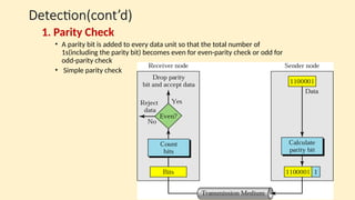
- 50. Detection(cont’d) Detection(cont’d) 1. Parity Check • A parity bit is added to every data unit so that the total number of 1s(including the parity bit) becomes even for even-parity check or odd for odd-parity check • Simple parity check
- 51. Detection -examples Detection -examplesExample 1 Example 1 Suppose the sender wants to send the word world. In ASCII the five characters are coded as 1110111 1101111 1110010 1101100 1100100 The following shows the actual bits sent 11101110 11011110 11100100 11011000 11001001
- 52. Detection – examples Detection – examples Example 2 Example 2 Now suppose the word world in Example 1 is received by the receiver without being corrupted in transmission. 11101110 11011110 11100100 11011000 11001001 The receiver counts the 1s in each character and comes up with even numbers (6, 6, 4, 4, 4). The data are accepted.
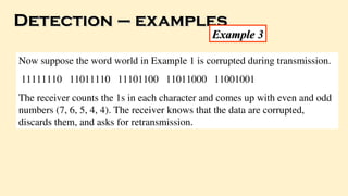
- 53. Detection – examples Detection – examples Example 3 Example 3 Now suppose the word world in Example 1 is corrupted during transmission. 11111110 11011110 11101100 11011000 11001001 The receiver counts the 1s in each character and comes up with even and odd numbers (7, 6, 5, 4, 4). The receiver knows that the data are corrupted, discards them, and asks for retransmission.
- 54. Two –Dimensional Parity Check Two –Dimensional Parity Check
- 55. Example 4 Example 4 Suppose the following block is sent: 10101001 00111001 11011101 11100111 10101010 However, it is hit by a burst noise of length 8, and some bits are corrupted. 10100011 10001001 11011101 11100111 10101010 When the receiver checks the parity bits, some of the bits
- 56. 2.CRC(Cyclic Redundancy Check) • Based on binary division.
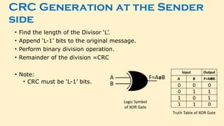
- 57. CRC Generation at the Sender side • Find the length of the Divisor ‘L’. • Append ‘L-1’ bits to the original message. • Perform binary division operation. • Remainder of the division =CRC • Note: • CRC must be ‘L-1’ bits.
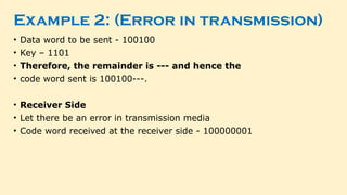
- 60. Example 2: (Error in transmission) • Data word to be sent - 100100 • Key – 1101 • Therefore, the remainder is --- and hence the • code word sent is 100100---. • Receiver Side • Let there be an error in transmission media • Code word received at the receiver side - 100000001
- 61. 3. CHECKSUM • Sender Side 1. Break the original message into ‘k’ number of blocks with ‘n’ bits in each block. 2. Sum all the ‘k’ data blocks. 3. Add the carry to the sum, if any. 4. Do 1’s complement to the sum = Checksum.
- 62. 3. CHECKSUM • Receiver Side 1. Break the bits of the message received from the sender into the 'k' number of blocks. 2. Now add all the blocks along with the checksum. 3. Perform the 1's complement to the result. 4. Now, there are two conditions: If the result is 0, the message has no loss/ error.
- 64. Detection(cont’d) Detection(cont’d) • Data unit and checksum
- 65. Detection(cont’d) Detection(cont’d) • At a sender Original data : 10101001 00111001 10101001 00111001 -------------- 11100010 Sum 00011101 Checksum(After 1’s Complement) 10101001 00111001 00011101
- 66. Detection(cont’d) Detection(cont’d) • At a receiver Received data : 10101001 00111001 00011101 10101001 00111001 00011101 --------------- 11111111 Sum 00000000 1’s Complement of Sum.
- 67. ERROR CONTROL
- 68. ERROR CONTROL • Error control includes both error detection and error correction. • Whenever an error is detected, specified frames are retransmitted • It allows the receiver to inform the sender if a frame is lost or damaged during transmission and coordinates the retransmission of those frames by the sender. • Includes the following actions: • Positive Acknowledgement (ACK): if the frame arrived with no errors • Negative Acknowledgement (NAK): if the frame arrived with errors • Retransmissions after Timeout: Frame is retransmitted after certain amount of time if no acknowledgement was received. • Error control in the data link layer is based on automatic repeat request (ARQ).
- 69. Categories of Error Control
- 70. 1. STOP-AND-WAIT ARQ • Stop-and-wait ARQ is a technique used to retransmit the data in case of damaged or lost frames. • This technique works on the principle that the sender will not transmit the next frame until it receives the acknowledgement of the last transmitted frame. • Two possibilities of the retransmission in Stop and Wait ARQ: • Damaged Frame • Lost Frame
- 71. 1. STOP-AND-WAIT PROTOCOL ARQ Sender Sender Receiver Data Frame 0 Data Frame 0 Data Frame 2 Data Frame 2 Data Frame 1 Data Frame 1 Data Frame 2 Data Frame 2 Damaged Frame
- 72. 1. STOP-AND-WAIT PROTOCOL ARQ Sender Sender Receiver Data Frame 0 Data Frame 0 Data Frame 2 Data Frame 2 Data Frame 1 Data Frame 1 Data Frame 2 Data Frame 2 Lost Frame
- 73. 2. SLIDING WINDOW ARQ • Sliding Window ARQ is a technique used for continuous transmission error control. • Two protocols used in sliding window ARQ: a. GO-BACK-N ARQ b. SELECTIVE-REJECT(REPEAT) ARQ
- 74. A. GO-BACK-N ARQ • In Go-Back-N ARQ protocol, if one frame is lost or damaged, then it retransmits all the frames after which it does not receive the positive ACK. Data Frame 0 Data Frame 0 Data Frame 2 Data Frame 2 Data Frame 1 Data Frame 1 Data Frame 3 Data Frame 3 Data Frame 4 Data Frame 4 Data Frame 2 Data Frame 2 Data Frame 3 Data Frame 3 Data Frame 4 Data Frame 4 NAK Discarded Discarded Discarded Resent Resent Resent
- 75. b. SELECTIVE-REJECT(REPEAT) ARQ • Only those frames are retransmitted for which negative acknowledgement (NAK) has been received. Data Frame 0 Data Frame 0 Data Frame 2 Data Frame 2 Data Frame 1 Data Frame 1 Data Frame 3 Data Frame 3 Data Frame 4 Data Frame 4 Data Frame 2 Data Frame 2 Data Frame 5 Data Frame 5 Data Frame 6 Data Frame 6 NAK Discarded Resent
- 77. DATA-LINK LAYER PROTOCOLS • Four protocols have been defined for the data-link layer controls. • They are 1. Simple Protocol 2. Stop-and-Wait Protocol 3. Go-Back-N Protocol 4. Selective-Repeat Protocol
- 78. 1. SIMPLE PROTOCOL • The first protocol is a simple protocol with neither flow nor error control. • We assume that the receiver can immediately handle any frame it receives. • In other words, the receiver can never be overwhelmed with incoming frames. • The data-link layers of the sender and receiver provide transmission services for their network layers.
- 79. SIMPLE PROTOCOL • FSMs for the simple protocol
- 80. SIMPLE PROTOCOL • Flow diagram
- 81. DATA-LINK LAYER PROTOCOLS 2. STOP-AND-WAIT PROTOCOL • REFER STOP AND WAIT FROM FLOW CONTROL 3. GO-BACK-N PROTOCOL • REFER GO-BACK-N ARQ FROM ERROR CONTROL 4. SELECTIVE-REPEAT PROTOCOL • REFER SELECTIVE-REPEAT ARQ FROM ERROR CONTROL
- 83. HDLC (HIGH-LEVEL DATA LINK CONTROL) • A group of communication protocols of the data link layer for transmitting data between network points or nodes. • Since it is a data link protocol, data is organized into frames. • A frame is transmitted via the network to the destination that verifies its successful arrival. • It is a bit - oriented protocol that is applicable for both point - to - point and multipoint communications.
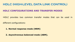
- 84. HDLC (HIGH-LEVEL DATA LINK CONTROL) HDLC CONFIGURATIONS AND TRANSFER MODES •HDLC provides two common transfer modes that can be used in different configurations: 1. Normal response mode (NRM) 2. Asynchronous balanced mode (ABM).
- 85. HDLC (HIGH-LEVEL DATA LINK CONTROL) Normal response mode (NRM)
- 86. HDLC (HIGH-LEVEL DATA LINK CONTROL) Normal response mode (NRM) • In normal response mode (NRM), the station configuration is unbalanced. • We have one primary station and multiple secondary stations. • A primary station can send commands; a secondary station can only respond. • The NRM is used for both point-to-point and multipoint links.
- 87. HDLC (HIGH-LEVEL DATA LINK CONTROL) Asynchronous balanced mode (ABM)
- 88. HDLC (HIGH-LEVEL DATA LINK CONTROL) Asynchronous balanced mode (ABM) • The link is point-to-point, and each station can function as a primary and a secondary (acting as peers). • The primary station still has the responsibility of doing initialization, error correction or recovery, the control flow of data, and logical disconnections.
- 89. HDLC (HIGH-LEVEL DATA LINK CONTROL) HDLC FRAME
- 90. HDLC (HIGH-LEVEL DATA LINK CONTROL) HDLC FRAME •Flag − It is an 8-bit sequence that marks the beginning and the end of the frame. The bit pattern of the flag is 01111110. •Address − It contains the address of the receiver. If the frame is sent by the primary station, it contains the address(es) of the ______ station(s). If it is sent by the secondary station, it contains the address of the _____ station. •Control − is 1 or 2 bytes containing flow and error control information. •Payload − carries the data from the network layer. Its length may vary from one network to another. •FCS − is a 2 byte or 4 bytes frame check sequence for error detection. The standard code used is CRC (cyclic redundancy code).
- 91. HDLC (HIGH-LEVEL DATA LINK CONTROL) TYPES HDLC FRAMES
- 92. HDLC (HIGH-LEVEL DATA LINK CONTROL) TYPES HDLC FRAMES •I-frame: I-frames or Information frames carry user data from the network layer. •They also include flow and error control information that is piggybacked on user data. •The first bit of the control field of the I-frame is 0.
- 93. HDLC (HIGH-LEVEL DATA LINK CONTROL) TYPES HDLC FRAMES •S-frame: S-frames or Supervisory frames do not contain an information field. •They are used for flow and error control when piggybacking is not required. •The first two bits of the control field of the S-frame are 10.
- 94. CONTROL FIELD FORMAT FOR THE DIFFERENT FRAME TYPES TYPES HDLC FRAMES •U-frame: U-frames or Un-numbered frames are used for myriad miscellaneous functions, like link management. •It may contain an information field if required. •The first two bits of the control field of the U-frame are 11.
- 95. CONTROL FIELD FORMAT FOR THE DIFFERENT FRAME TYPES Control Field for I-Frames
- 96. CONTROL FIELD FORMAT FOR THE DIFFERENT FRAME TYPES Control Field for S-Frames
- 97. CONTROL FIELD FORMAT FOR THE DIFFERENT FRAME TYPES Control Field for U-Frames
- 99. POINT-TO-POINT PROTOCOL (PPP) • Point-to-Point Protocol (PPP) was devised by IETF (Internet Engineering Task Force) in 1990 as a Serial Line Internet Protocol (SLIP). • PPP is a data link layer communications protocol used to establish a direct connection between two nodes. • It connects two routers directly without any host or any other networking device in between. • It is used to connect the Home PC to the server of ISP via a modem. • It is a byte - oriented protocol that is widely used in broadband communications having heavy loads and high speeds. • Since it is a data link layer protocol, data is transmitted in frames. It is also known as RFC 1661.
- 100. POINT-TO-POINT PROTOCOL (PPP) Point-to-Point Protocol (PPP) is a data link layer protocol that facilitates direct communication between two network nodes over serial links, such as •telephone lines •fiber optics, •dedicated leased lines.
- 101. MAIN SERVICES PROVIDED BY PPP: 1. Frame Format Definition: o Defines the structure of frames for data transmission, including fields like flag, address, control, protocol, data, and checksum. 2. Link Establishment and Data Exchange: o Specifies procedures for establishing, maintaining, and terminating a link between two devices. o Uses the Link Control Protocol (LCP) to manage the connection. 3. Encapsulation of Network Layer Data: o Provides a method to encapsulate Network Layer packets (e.g., IP, IPX, AppleTalk) into PPP frames. o Uses PPP Protocol Field to specify the encapsulated protocol type.
- 102. MAIN SERVICES PROVIDED BY PPP: 4. Authentication Mechanisms: o Supports authentication using: PAP (Password Authentication Protocol) – Basic authentication using username and password. CHAP (Challenge Handshake Authentication Protocol) – More secure authentication with challenge-response mechanism. 5. Addressing for Network Communication: o Assigns and manages IP addresses dynamically to the connected nodes. o Uses IP Control Protocol (IPCP) for address negotiation. 6. Multi-Link Connection Support: o Supports Multi-Link PPP (MLPPP) to combine multiple physical links into a single logical link, improving bandwidth and redundancy.
- 103. MAIN SERVICES PROVIDED BY PPP: 7. Support for Multiple Network Layer Protocols: o PPP is protocol-independent and can support various network layer protocols, including: IPv4, IPv6, Novell IPX, AppleTalk, and OSI protocols. o Uses Network Control Protocols (NCPs) to handle different network layer protocols.
- 104. PPP FRAME • Flag − 1 byte that marks the beginning and the end of the frame. The bit pattern of the flag is 01111110. • Address − 1 byte which is set to 11111111 in case of broadcast. • Control − 1 byte set to a constant value of 11000000. • Protocol − 1 or 2 bytes that define the type of data contained in the payload field. • Payload − This carries the data from the network layer. The maximum length of the payload field is 1500 bytes. However, this may be negotiated between the endpoints of communication. • FCS − It is a 2 byte or 4 bytes frame check sequence for error detection. The standard code
- 105. TRANSITION PHASES IN PPP
- 107. COMPONENTS/PROTOCOLS OF PPP 1. Link Control Protocol (LCP) 2. Authentication Protocols (AP) i. Password Authentication Protocol (PAP) ii. Challenge Handshake Authentication Protocol (CHAP) 3. Network Control Protocols (NCP)
- 108. 1. LINK CONTROL PROTOCOL (LCP) - Functions • Link Establishment • Negotiates and sets up communication parameters between two endpoints before data transmission begins. • Uses LCP packets encapsulated in PPP frames. • Authentication • Supports authentication protocols like PAP and CHAP. • Ensures secure access control. • Link Configuration • Determines options like frame size, error detection, and compression techniques. • Adjusts link parameters for efficient data transfer. • Error Detection and Quality Maintenance • Detects link errors and decides whether to terminate or re-establish the connection. • Implements (LQM) to check link performance. • Link Termination • Closes the connection gracefully when data transfer is complete or an error occurs. • Sends a (TERM-REQ) message to notify the remote system.
- 109. 2. Authentication Protocols (AP) - PAP • PAP follows a two-way handshake mechanism: 1.Client Sends Credentials: o When the link enters the Authenticate state, the client (PPP peer) sends a username and password to the server in plaintext. 2.Server Validates Credentials: o The authentication server checks the received username and password against a stored database or authentication system. 3.Authentication Decision: o If the credentials are valid, the server grants access, and PPP moves to the Network state for further configuration. o If authentication fails, the connection is terminated, and the system moves back to the Dead state.
- 110. 2. Authentication Protocols (AP) - CHAP • CHAP follows a three-way handshake mechanism: 1.Challenge (Server → Client) o The server sends a random challenge value (nonce) to the client. 2.Response (Client → Server) o The client generates a hash (using the challenge value and its stored password) and sends it back to the server. 3.Verification (Server validates the hash) o The server checks the received hash against its own computed hash. o If they match, authentication succeeds, and PPP moves to the Network State. o If authentication fails, the connection is terminated (returns to Dead State).
- 111. 3. Network Control Protocols (NCP) 1. Network Layer Configuration • Assigns and configures network addresses (e.g., IP address). • Negotiates parameters specific to a particular network protocol. 2. Encapsulation of Network Protocols • Determines how network layer packets (e.g., IP, IPv6, AppleTalk) will be formatted and transmitted. 3. Dynamic Address Assignment • Works with DHCP to assign dynamic IP addresses in PPP-based connections. 4. Error Handling & Protocol Support • Manages errors in network layer protocol configuration. • Supports multiple network protocols by maintaining separate NCP modules. 5. Network Protocol Termination • Terminates the network layer connection when the PPP session ends.
- 113. MEDIA ACCESS CONTROL (MAC) When two or more nodes transmit data at the same time, their frames will collide and the link bandwidth is wasted during collision. To coordinate the access of multiple sending/receiving nodes to the shared link, we need a protocol to coordinate the transmission. These protocols are called Medium or Multiple Access Control (MAC) Protocols. MAC belongs to the data link layer of OSI model. MAC defines rules for orderly access to the shared medium. It tries to ensure that no two nodes are interfering with each other’s transmissions, and deals with the situation when they do.
- 114. MEDIA ACCESS CONTROL (MAC)
- 115. MEDIA ACCESS CONTROL (MAC)
- 116. ISSUES INVOLVED IN MAC • Where the control is exercised? - refers to whether the control is exercised in a centralized or distributed manner • How the control is exercised? - refers to in what manner the control is exercised
- 117. 1. Where the Control is Exercised? A. Centralized MAC Control •A single central controller or node decides which device can access the medium. •Reduces collisions and improves efficiency but introduces a single point of failure. •Examples: • Polling: A central device (e.g., access point in Wi-Fi) asks each node when it wants to transmit. • Token Passing: A special frame (token) circulates, allowing only the holder to transmit. • TDMA (Time Division Multiple Access): A base station assigns time slots to users.
- 118. 1. Where the Control is Exercised? B. Distributed MAC Control •Each device independently decides when to transmit based on predefined rules. •More scalable and fault-tolerant but can lead to collisions. •Examples: • CSMA/CA (Wi-Fi): Devices sense the channel and transmit only when it is free. • CSMA/CD (Ethernet): Devices sense the channel, detect collisions, and retransmit. • ALOHA: Devices transmit randomly; collisions are handled by retransmissions.
- 119. 2. How the Control is Exercised? A. Contention-Based Access (Random Access) •Devices compete for access to the medium. •Efficient in low-traffic networks but causes collisions under heavy load. •Examples: • ALOHA & Slotted ALOHA: Devices transmit at any time (ALOHA) or at fixed time slots (Slotted ALOHA). • CSMA/CD (Ethernet): Detects and handles collisions. • CSMA/CA (Wi-Fi): Avoids collisions by sensing before transmission.
- 120. 2. How the Control is Exercised? B. Scheduled Access (Deterministic Access) •Access is pre-determined, avoiding collisions. •Works well for real-time applications (e.g., VoIP, industrial automation). •Examples: • TDMA (Time Division Multiple Access): Assigns fixed time slots. • FDMA (Frequency Division Multiple Access): Assigns separate frequency bands. • CDMA (Code Division Multiple Access): Uses unique codes for simultaneous transmission.
- 121. MAC TYPES • Round-Robin : – Each station is given opportunity to transmit in turns. Either a central controller polls a station to permit to go, or stations can coordinate among themselves. • Reservation : - Station wishing to transmit makes reservations for time slots in advance. (Centralized or distributed). • Contention (Random Access) : - No control on who tries; If collision occurs, retransmission takes place.
- 122. MECHANISMS USED • Wired Networks : • CSMA / CD – Carrier Sense Multiple Access / Collision Detection • Wireless Networks : • CSMA / CA – Carrier Sense Multiple Access / Collision Avoidance
- 123. CARRIER SENSE MULTIPLE ACCESS/ COLLISION DETECTION (CSMA / CD)
- 124. CSMA / CD • Carrier Sense in CSMA/CD means that all the nodes sense the medium to check whether it is idle or busy. • If the carrier sensed is idle, then the node transmits the entire frame. • If the carrier sensed is busy, the transmission is postponed. • Collision Detection ensures that a device can recognize when its transmitted frame collides with another frame on the shared network medium.
- 125. CSMA / CD
- 126. CSMA / CD Transmitter Algorithm in CSMA/CD •Transmitter Algorithm defines the procedures for a node that senses a busy medium. •Three types of Transmitter Algorithm exist. •They are • Non-Persistent Strategy • Persistent Strategy : 1-Persistent & P-Persistent
- 127. TRANSMITTER ALGORITHM IN CSMA/CD • Non-Persistent Strategy • In the non-persistent method, a station that has a frame to send senses the line. • If the line is idle, it sends immediately. • If the line is not idle, it waits a random amount of time and then senses the line again. • The chance of two stations colliding is lower compared to other CSMA approaches. • This reduces collisions, but the network efficiency drops because the medium may remain idle when stations are ready to transmit.
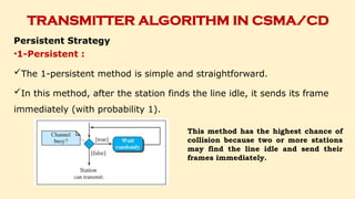
- 128. TRANSMITTER ALGORITHM IN CSMA/CD Persistent Strategy •1-Persistent : The 1-persistent method is simple and straightforward. In this method, after the station finds the line idle, it sends its frame immediately (with probability 1). This method has the highest chance of collision because two or more stations may find the line idle and send their frames immediately.
- 129. TRANSMITTER ALGORITHM IN CSMA/CD P-Persistent : • In this method, after the station finds the line idle it follows these steps: 1.With probability p, the station sends its frame. 2.With probability q = 1 − p, the station waits for the beginning of the next time slot and checks the line again. a. If the line is idle, it goes to step 1. b. If the line is busy, it acts as though a collision has occurred and uses the backoff procedure.
- 130. TRANSMITTER ALGORITHM IN CSMA/CD P-Persistent :
- 131. CSMA / CD • A Starts sending the first bit of its frame at t1. • And since C sees the channel idle at t2, starts sending its frame at t2. • C detects A’s frame at t3 and aborts transmission. • A detects C’s frame at t4 and aborts its transmission. • Transmission time for C’s frame is, therefore, t3-t2 • And for A’s frame is t4-t1
- 132. EXPONENTIAL BACK-OFF • Once an adaptor has detected a collision and stopped its transmission, it waits a certain amount of time and tries again. • Each time it tries to transmit but fails, the adaptor doubles the amount of time it waits before trying again. • This strategy of doubling the delay interval between each retransmission attempt is a general technique known as exponential back-off.
- 133. EXPONENTIAL BACK-OFF
- 134. CARRIER SENSE MULTIPLE ACCESS/ COLLISION AVOIDENCE (CSMA / CA)
- 135. CSMA / CA • Carrier sense multiple access with collision avoidance (CSMA/CA) was invented for wireless networks. • Wireless protocol would follow exactly the same algorithm as the Ethernet—Wait until the link becomes idle before transmitting and back off should a collision occur. • Collisions are avoided through the use of CSMA/CA’s three strategies: 1. The interframe space 2. The contention window 3. Acknowledgments
- 136. CSMA / CA Interframe Space (IFS) • First, collisions are avoided by deferring transmission even if the channel is found idle. • When an idle channel is found, the station does not send immediately. • It waits for a period of time called the interframe space or IFS
- 137. CSMA / CA Contention Window: •The contention window is an amount of time divided into slots. •A station that is ready to send chooses a random number of slots as its wait time. •The number of slots in the window changes according to the binary exponential backoff strategy. •This means that it is set to one slot the first time and then doubles each time the station cannot detect an idle channel after the IFS time.
- 138. CSMA / CA Acknowledgment: •In addition, the data may be corrupted during the transmission. •The positive acknowledgment and the time-out timer can help guarantee that the receiver has received the frame.
- 139. WIRED LAN : ETHERNET (IEEE 802.3)
- 140. WIRED LAN : ETHERNET (IEEE 802.3) • Ethernet was developed in the mid-1970’s at the Xerox Palo Alto Research Center (PARC), • IEEE controls the Ethernet standards. • The Ethernet is the most successful local area networking technology, that uses bus topology. • The Ethernet is multiple-access networks that is set of nodes send and receive frames over a shared link. • Ethernet uses the CSMA / CD mechanism.
- 142. EVOLUTION OF ETHERNET Ethernet Type Speed Technology Used Use Cases Advantages Limitations Standard Ethernet 10 Mbps Coaxial cables, Twisted-pair Early networks, basic internet usage Simple, widely used initially Slow for modern applications Fast Ethernet 100 Mbps Twisted-pair, Fiber optics Homes, offices (late 1990s) 10x faster than Standard Ethernet Insufficient for high-speed tasks Gigabit Ethernet 1 Gbps (1000 Mbps) Twisted-pair, Fiber optics Modern home, office, and data center networks Handles HD streaming, large files Requires high- quality cables Ten-Gigabit Ethernet 10 Gbps (10,000 Mbps) Fiber optics, High-end cables Data centers, cloud computing, high-performance networks Ultra-fast, minimal delays Expensive infrastructure
- 143. WIRELESS LAN ( IEEE 802.11)
- 144. WIRELESS LAN ( IEEE 802.11) • Wireless communication is one of the fastest-growing technologies. • The demand for connecting devices without the use of cables is increasing everywhere. • Wireless LANs can be found on college campuses, in office buildings, and in many public areas.
- 145. WIRELESS LAN ( IEEE 802.11) ADVANTAGES •Flexibility: Within radio coverage, nodes can access each other as radio waves can penetrate even partition walls. •Planning : No prior planning is required for connectivity as long as devices follow standard convention •Design : Allows to design and develop mobile devices. •Robustness : Wireless network can survive disaster. If the devices survive, communication can still be established. DISADVANTAGES •Quality of Service : Low bandwidth (1 – 10 Mbps), higher error rates due to interference, delay due to error correction and detection. •Cost : Wireless LAN adapters are costly. •Proprietary Solution : Due to slow standardization process, many solution are proprietary that limit the homogeneity of operation. •Restriction : Individual countries have their own radio spectral policies. This restricts the development of the technology. •Safety and Security : Wireless Radio waves may interfere with other devices. Eg; In a hospital, radio waves may interfere with high-tech equipment.
- 146. TECHNOLOGY USED IN WLAN / 802.11 • WLAN’s uses Spread Spectrum (SS) technology. • The idea behind Spread spectrum technique is to spread the signal over a wider frequency band than normal, so as to minimize the impact of interference from other devices. • There are two types of Spread Spectrum: • Frequency Hopping Spread Spectrum (FHSS) • Direct Sequence Spread Spectrum (DSSS)
- 147. WHAT IS SPREAD SPECTRUM? • Spread spectrum is a method of transmitting radio signals over a wide range of frequencies. • It spreads the signal over a broader bandwidth than the minimum required to send the information, which provides advantages such as • increased resistance to interference, • improved security, • and enhanced privacy. • The ‘spread code’ is a patterned series of numbers that enlarges the original signal’s bandwidth.
- 148. SPREAD SPECTRUM
- 149. DIRECT SEQUENCE SPREAD SPECTRUM • Direct Sequence Spread Spectrum (DSSS) System, which is commonly used in wireless communication to enhance security and resistance to interference. • It consists of a DSSS Transmitter Part and a DSSS Receiver Part.
- 150. DSSS TRANSMITTER PART • Data Input: The original data signal is provided as input. • Pseudorandom Sequence (PRS) Generator: A pseudorandom sequence (spreading code) is generated, which is used to spread the signal over a wider bandwidth. • Mixer (Multiplication): The input data is mixed with the PRS, spreading it over a broad spectrum. • Wideband Modulator: The spread signal is modulated onto a carrier frequency. • Carrier Generator: Provides the required carrier signal for modulation. • Transmission: The modulated signal is transmitted over the communication channel.
- 151. DSSS RECEIVER PART • Wideband Demodulator: The received signal is demodulated using the carrier signal. • Carrier Generator: Generates the carrier signal for demodulation. • Pseudorandom Sequence (PRS) Generator: The same spreading code used at the transmitter is regenerated. • Mixer (De-spreading): The demodulated signal is multiplied with the PRS to extract the original data. • Data Output: The recovered original data is output.
- 152. DIRECT SEQUENCE SPREAD SPECTRUM
- 153. FREQUENCY HOPPING SPREAD SPECTRUM • The frequency-hopping spread spectrum is a method of transmitting radio signals by rapidly switching a carrier among many frequency channels, using a pseudorandom sequence known to both transmitter and receiver.
- 154. TRANSMITTER SECTION • Input Signal: The original data that needs to be transmitted. • Modulation: The input signal is modulated using a carrier signal, which is generated by the Carrier Signal Generator. • Spreading: The modulated signal is further multiplied with a spreading signal, which is controlled by the Frequency Generator. • This step ensures that the signal hops between different frequencies in a predetermined sequence. • Transmission: The frequency-hopped signal is then transmitted through the wireless channel.
- 155. RECEIVER SECTION • Receiving the Signal: The receiver captures the transmitted signal. • Despreading: The received signal is multiplied with the same spreading signal (from the Frequency Generator) used at the transmitter to reverse the frequency hopping. • Demodulation: The despread signal is then multiplied with the carrier signal to retrieve the original data. • Filtering: A filter is applied to remove any unwanted noise and interference. • Output Signal: The original signal is recovered and sent to the output.
- 156. FREQUENCY HOPPING SPREAD SPECTRUM
- 157. TOPOLOGY IN WLAN / 802.11
- 158. TOPOLOGY IN WLAN / 802.11
- 159. ARCHITECURE OF WLAN / 802.11 Basic Service Set (BSS) •The Basic Service Set (BSS) is a group of wireless devices, such as laptops or smartphones, that communicate with each other within a specific network.
- 160. ARCHITECURE OF WLAN / 802.11 Extended service sets (ESSs) •ESS is a collection of multiple BSSs working together as a single network, typically managed by a controller. •It allows for larger coverage areas and seamless roaming between different BSSs under the same network SSID.
- 161. HIDDEN NODE PROBLEM
- 162. EXPOSED NODE PROBLEM
- 163. DISTRIBUTION SYSTEM IN WLAN / 802.11
- 164. DISTRIBUTION SYSTEM IN WLAN / 802.11 • Scanning Process in Distribution System • The technique for selecting an Access Point is called scanning. • Scanning will take place whenever a node joins the network as well as when it is not satisfied with the current access point signal. • It involves the following four steps: • The node sends a Probe Request frame. • All AP’s within reach reply with a Probe Response frame. • The node selects one of the access points and sends that AP an Association Request frame. • The AP replies with an Association Response frame. There are two types of Scanning. They are • Active Scanning • Passive Scanning
- 165. SCANNING
- 167. BLUETOOTH (IEEE 802.15.1 ) • Ad hoc Network: Bluetooth forms temporary connections between devices without a fixed infrastructure. • Purpose: Connects devices like phones, laptops, cameras, and printers over short distances. • Standard: Based on IEEE 802.15, which defines Wireless Personal Area Networks (WPANs). • Frequency: Operates in the 2.4 GHz ISM band (unlicensed). • Range: • Standard: Up to 10 meters (30 feet). • Extended: Can reach 100 meters with increased power.
- 168. BLUETOOTH (IEEE 802.15.1 ) • Ad hoc Network: Bluetooth forms temporary connections between devices without a fixed infrastructure. • Purpose: Connects devices like phones, laptops, cameras, and printers over short distances. • Standard: Based on IEEE 802.15, which defines Wireless Personal Area Networks (WPANs). • Frequency: Operates in the 2.4 GHz ISM band (unlicensed). • Range: • Standard: Up to 10 meters (30 feet). • Extended: Can reach 100 meters with increased power.
- 169. BLUETOOTH (IEEE 802.15.1 ) • Speed: Transfers data at 1 to 3 Mbps. • Governance: Managed by the Bluetooth Special Interest Group (SIG). • Connections: Supports up to 8 devices in a network (1 master, 7 slaves). • Interference Avoidance: Uses Frequency Hopping Spread Spectrum (FHSS). • Types of Links: • ACL (Asynchronous Connectionless Link): For data transfer. • SCO (Synchronous Connection-Oriented Link): For audio/voice communication.
- 171. piconet Active Device / State • Connected to the piconet and participates in the communication. • Can be a Master or a Slave device. • All active devices are assigned a 3-bit address. Parked Device / State • Connected to the piconet, but does not actively participate in the communication. • More than 200 devices can be parked. • All parked devices use an 8-bit parked member address (PMA). Stand-by Device / State • Not connected to the piconet. • They do not participate in the piconet currently but may take part at a later time. • Devices in stand-by do not need an address.
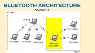
- 173. SCATTERNET • Piconets can be combined to form what is called a scatternet. • Many piconets with overlapping coverage can exist simultaneously, called Scatternet. • A secondary station in one piconet can be the primary in another piconet. • This station can receive messages from the primary in the first piconet (as a secondary) and, acting as a primary, deliver them to secondary's in the second piconet.
- 174. BLUETOOTH LAYERS
- 175. BLUETOOTH LAYERS • Radio Layer • The radio layer is roughly equivalent to the physical layer of the Internet model. • Bluetooth uses the frequency-hopping spread spectrum (FHSS) method in the physical layer to avoid interference from other devices or other networks. • Bluetooth hops 1600 times per second, which means that each device changes its modulation frequency 1600 times per second. • To transform bits to a signal, Bluetooth uses a sophisticated version of FSK, called GFSK.
- 176. BLUETOOTH LAYERS • Baseband Layer • The baseband layer is roughly equivalent to the MAC sublayer in LANs. • The access method is TDMA. • The primary and secondary stations communicate with each other using time slots. The length of a time slot is exactly 625 µs. • During that time, a primary sends a frame to a secondary, or a secondary sends a frame to the primary.
- 177. BLUETOOTH LAYERS • L2CAP • The Logical Link Control and Adaptation Protocol, or L2CAP (L2 here means LL) is equivalent to the LLC sublayer in LANs. • It is used for data exchange on an ACL link. • SCO channels do not use L2CAP. • The L2CAP functions are : multiplexing, segmentation and reassembly, quality of service (QoS), and group management.
- 178. CONNECTING DEVICES
- 179. CONNECTING DEVICES
- 180. CONNECTING DEVICES • The five categories contain devices which can be defined as: Those which operate below the physical layer such as a passive hub. Those which operate at the physical layer (a repeater). Those which operate at the physical and data link layers (a bridge). Those which operate at the physical, data link, and network layers (a router). Those which can operate at all five layers (a gateway).
- 181. CONNECTING DEVICES
- 182. HUBS • Several networks need a central location to connect media segments together. These central locations are called as hubs. • The hub organizes the cables and transmits incoming signals to the other media segments. • The three types of hubs are: • Passive hub - Connector • Active Hub - Multiport repeater • Intelligent Hub - Program of network management
- 183. REPEATERS • A repeater is a device that operates only in the physical layer. • Signals that carry information within a network can travel a fixed distance before attenuation endangers the integrity of the data. • A repeater receives a signal and, before it becomes too weak or corrupted, regenerates the original bit pattern. • The repeater then sends the refreshed signal.
- 184. BRIDGES • Bridges operate in physical layer as well as data link layer. • As a physical layer device, they regenerate the receive signal. • As a data link layer, the bridge checks the physical (MAC) address contained in the frame. • The bridge has a filtering feature. • It can check the destination address of a frame and decides, if the frame should be forwarded or dropped. • Bridges are used to connect two or LANs working on the same protocol.
- 185. SWITCHES • A switch is a small hardware device which is used to join multiple computers together with one local area network (LAN). • A switch is a mechanism that allows us to interconnect links to form a large network. • It does not broadcast the message as it works with limited bandwidth. • A Switch is used to transfer the data only to the device that has been addressed.
- 186. ROUTERS • A router is a three-layer device. • It operates in the physical, data-link, and network layers. • As a physical-layer device, it regenerates the signal it receives. • As a link-layer device, the router checks the physical addresses (source and destination) contained in the packet. • As a network-layer device, a router checks the network-layer addresses. • A router is a device like a switch that routes data packets based on their IP addresses. • A router can connect networks. A router connects the LANs and WANs on the internet.
- 187. ROUTERS
- 188. GATEWAY • A gateway is a device, which operates in all five layers of the internet or seven layers of OSI model. • It is usually a combination of hardware and software. • Gateway connects two independent networks. • Gateways are generally more complex than switch or router. • Gateways basically works as the messenger agents that take data from one system, interpret it, and transfer it to another system. • Gateways are also called protocol converters. • A gateway accepts a packet formatted for one protocol and converts it to a packet formatted to another protocol before forwarding it. • The gateway must adjust the data rate, size and data format.
- 189. BROUTER • Brouter is a hybrid device. It combines the features of both bridge and router. • Brouter is a combination of Bridge and Router. • Functions as a bridge for nonroutable protocols and a router for routable protocols. • As a router, it is capable of routing packets across networks. • As a bridge, it is capable of filtering local area network traffic. • Provides the best attributes of both a bridge and a router. • Operates at both the Data Link and Network layers and can replace separate bridges and routers.