


![Elements of verilog- data type
Nets
Nets are physical connections between devices
Many types of nets, but all we care about is wire.
Declaring a net
wire [<range>] <net_name> ;
Range is specified as [MSb:LSb]. Default is one bit wide
Registers
Implicit storage-holds its value until a new value is assigned to it.
Register type is denoted by reg.
Declaring a register
reg [<range>] <reg_name>;
Parameters are not variables, they are constants.](https://image.slidesharecdn.com/verilogspk1-191217074954/85/Verilogspk1-21-320.jpg)


![Verilog keywords
Input Declaration
• Scalar
input list of input identifiers;
Example: input A, B, c_in;
• Vector
input[range] list of input identifiers;
Example: input[15:0] A, B, data;
Output Declaration
• Scalar Example: output c_out, OV, MINUS;
• Vector Example: output[7:0] ACC, REG_IN,
data_out;](https://image.slidesharecdn.com/verilogspk1-191217074954/85/Verilogspk1-30-320.jpg)


![VERILOG coding for all gate
module gates(a, b, y1, y2, y3, y4, y5, y6, y7);
input [3:0] a, b;
output [3:0] y1, y2, y3, y4, y5, y6, y7;
/* Seven different logic gates acting on four bit busses */
assign y1= ~a; // NOT gate
assign y2= a & b; // AND gate
assign y3= a | b; // OR gate
assign y4= ~(a & b); // NAND gate
assign y5= ~(a | b); // NOR gate
assign y6= a ^ b; // XOR gate
assign y7= ~(a ^ b); // XNOR gate
endmodule](https://image.slidesharecdn.com/verilogspk1-191217074954/85/Verilogspk1-35-320.jpg)


![Example 4-bit adder
module add4 (s,c3,ci,a,b)
input [3:0] a,b ; // port declarations
input ci ;
output [3:0] s : // vector
output c3 ;
wire [2:0] co ;
add a0 (co[0], s[0], a[0], b[0], ci) ;
add a1 (co[1], s[1], a[1], b[1], co[0]) ;
add a2 (co[2], s[2], a[2], b[2], co[1]) ;
add a3 (c3, s[3], a[3], b[3], co[2]) ;
endmodule
a0a1a2a3c3 ci
Simpler than VHDL
Only Syntactical
Difference](https://image.slidesharecdn.com/verilogspk1-191217074954/85/Verilogspk1-38-320.jpg)


![Procedural Statements: if
if (expr1)
true_stmt1;
else if (expr2)
true_stmt2;
..
else
def_stmt;
E.g. 4-to-1 mux:
module mux4_1(out, in, sel);
output out;
input [3:0] in;
input [1:0] sel;
reg out;
wire [3:0] in;
wire [1:0] sel;
always @(in or sel)
if (sel == 0)
out = in[0];
else if (sel == 1)
out = in[1];
else if (sel == 2)
out = in[2];
else
out = in[3];
endmodule](https://image.slidesharecdn.com/verilogspk1-191217074954/85/Verilogspk1-44-320.jpg)
![Procedural Statements: case
case (expr)
item_1, .., item_n: stmt1;
item_n+1, .., item_m: stmt2;
..
default: def_stmt;
endcase
E.g. 4-to-1 mux:
module mux4_1(out, in, sel);
output out;
input [3:0] in;
input [1:0] sel;
reg out;
wire [3:0] in;
wire [1:0] sel;
always @(in or sel)
case (sel)
0: out = in[0];
1: out = in[1];
2: out = in[2];
3: out = in[3];
endcase
endmodule](https://image.slidesharecdn.com/verilogspk1-191217074954/85/Verilogspk1-45-320.jpg)
![Decoder
3-to 8 decoder with an
enable control
module decoder(o,enb_,sel) ;
output [7:0] o ;
input enb_ ;
input [2:0] sel ;
reg [7:0] o ;
always @ (enb_ or sel)
if(enb_)
o = 8'b1111_1111 ;
else
case(sel)
3'b000 : o = 8'b1111_1110 ;
3'b001 : o = 8'b1111_1101 ;
3'b010 : o = 8'b1111_1011 ;
3'b011 : o = 8'b1111_0111 ;
3'b100 : o = 8'b1110_1111 ;
3'b101 : o = 8'b1101_1111 ;
3'b110 : o = 8'b1011_1111 ;
3'b111 : o = 8'b0111_1111 ;
default : o = 8'bx ;
endcase
endmodule](https://image.slidesharecdn.com/verilogspk1-191217074954/85/Verilogspk1-46-320.jpg)


![A counter which runs through counts 0, 1, 2, 4, 9, 10, 5, 6, 8, 7, 0, …
Sequence counter
module CntSeq(clk, reset, state);
parameter n = 4;
input clk, reset;
output [n-1:0]state;
reg1:0]state;
[n- integer k;
//
always @(posedge clk)
if(reset)
state = 0;
else begin
case (state)
4'b0000:state = 4'b0001; //0 -> 1
4'b0001:state = 4'b0010; //1 -> 2
4'b0010:state = 4'b0100; //2 -> 4
4'b0100:state = 4'b1001; //4 -> 9
4'b1001:state = 4'b1010; //9 -> 10
4'b1010:state = 4'b0101; //10-> 5
4'b0101:state = 4'b0110; //5 -> 6
4'b0110:state = 4'b1000; //6 -> 8
4'b1000:state = 4'b0111; //8 -> 7
default:state = 4'b0000;
endcase
end
endmodule](https://image.slidesharecdn.com/verilogspk1-191217074954/85/Verilogspk1-50-320.jpg)


![module _4bit_adder (S,C4,A,B,C0);
input [3:0] A,B;
input C0;
output [3:0] S;
output C4;
wire C1,C2,C3; //Intermediate carries
//Instantiate the full adder
fulladder FA0 (S[0],C1,A[0],B[0],C0),
FA1 (S[1],C2,A[1],B[1],C1),
FA2 (S[2],C3,A[2],B[2],C2),
FA3 (S[3],C4,A[3],B[3],C3);
endmodule
4-bit Full Adder](https://image.slidesharecdn.com/verilogspk1-191217074954/85/Verilogspk1-53-320.jpg)

![//Gate-level description of a 2-to-4-line decoder
module decoder_gl (A,B,E,D);
input A,B,E;
output[0:3]D;
wire Anot,Bnot,Enot;
not
n1 (Anot,A),
n2 (Bnot,B),
n3 (Enot,E);
nand
n4 (D[0],Anot,Bnot,Enot),
n5 (D[1],Anot,B,Enot),
n6 (D[2],A,Bnot,Enot),
n7 (D[3],A,B,Enot);
endmodule
2 to 4 Decoder](https://image.slidesharecdn.com/verilogspk1-191217074954/85/Verilogspk1-55-320.jpg)


![Behavioral Modeling (4)
//Behavioral description of 4-to-1 line mux
module mux4x1_bh (i0,i1,i2,i3,select,y);
input i0,i1,i2,i3;
input [1:0] select;
output y;
reg y;
always @(i0 or i1 or i2 or i3 or select)
case (select)
2'b00: y = i0;
2'b01: y = i1;
2'b10: y = i2;
2'b11: y = i3;
endcase
endmodule](https://image.slidesharecdn.com/verilogspk1-191217074954/85/Verilogspk1-58-320.jpg)


![Sequence Recognizer
module seq_recognizer(CLK,RST,X,Z);
input CLK,RST,X;
output Z;
reg [1:0]state, next_state;
parameter A=2’b00,B=2’b01,C=2’b10,D=2’b11;
reg Z;
always@(posedge CLK or posedge RST) begin
if(RST==1) state <= A;
else state <= next_state;
end](https://image.slidesharecdn.com/verilogspk1-191217074954/85/Verilogspk1-64-320.jpg)

Verilogspk1
- 1. Supriya P Kurlekar Department of Electronics and Telecommunication Engg. (Sharad Institute of technology college of Engg.)
- 2. Verilog Background Developed by Gateway Design Automation (1980) Later acquired by Cadence Design(1989) who made it public in 1990 Became a standardized in 1995 by IEEE (Std 1364) regulated by Open Verilog International (OVI)
- 3. VHDL Background VHSIC Hardware Description Language. VHSIC is an abbreviation for Very High Speed Integrated Circuit. Developed by the department of defense (1981) In 1986 rights where given to IEEE Became a standard and published in 1987 Revised standard we know now published in 1993 (VHDL 1076-1993) regulated by VHDL international (VI)
- 4. What is verilog? Verilog is a HDL- hardware description language to design the digital system. VHDL is other hardware description language. Virtually every chip (FPGA, ASIC, etc.) is designed in part using one of these two languages Verilog was introduced in 1985 by Gateway Design System Corporation
- 5. verilog IEEE 1364-2001 is the latest Verilog HDL standard Verilog is case sensitive (Keywords are in lowercase) The Verilog is both a behavioral and a structure language
- 6. Difference between VERILOG and VHDL Verilog is similar to c- language. VHDL is similar to Ada- (ada is a structured, statically typed, imperative, wide-spectrum, and object-oriented high-level computer programming language, extended from Pascal ) Many feel that Verilog is easier to learn and use than VHDL.
- 7. 7 Lexical Conventions Very similar to C Verilog is case-sensitive All keywords are in lowercase A Verilog program is a string of tokens Whitespace Comments Delimiters Numbers Strings Identifiers Keywords
- 8. 8 Lexical Conventions (cont’d) Whitespace Blank space (b) Tab (t) Newline (n) Whitespace is ignored in Verilog except In strings When separating tokens Comments Used for readability and documentation Just like C: // single line comment /* multi-line comment */ /* Nested comments /* like this */ may not be acceptable (depends on Verilog compiler) */
- 9. Lexical Conventions (cont’d) Operators Unary a = ~b; Binary a = b && c; Ternary a = b ? c : d; // the only ternary operator
- 10. Lexical Conventions (cont’d) Number Specification Sized numbers Unsized numbers Unknown and high-impedance values Negative numbers
- 11. 2 Verilog HDL 11 Lexical Conventions (cont’d) Sized numbers General syntax: <size>’<base><number> <size> number of bits (in decimal) <number> is the number in radix <base> <base> : d or D for decimal (radix 10) b or B for binary (radix 2) o or O for octal (radix 8) h or H for hexadecimal (radix 16) Examples: 4’b1111 12’habc 16’d255 Unsized numbers Default base is decimal Default size is at least 32 (depends on Verilog compiler) Examples 23232 ’habc ’o234
- 12. Verilog HDL 12 Lexical Conventions (cont’d) X or Z values Unknown value: lowercase x 4 bits in hex, 3 bits in octal, 1 bit in binary High-impedance value: lowercase z 4 bits in hex, 3 bits in octal, 1 bit in binary Examples 12’h13x 6’hx 32’bz Extending the most-significant part Applied when <size> is bigger than the specified value Filled with x if the specified MSB is x Filled with z if the specified MSB is z Zero-extended otherwise Examples: 6’hx
- 13. Verilog HDL 13 Lexical Conventions (cont’d) Negative numbers Put the sign before the <size> Examples: -6’d3 4’d-2 // illegal Two’s complement is used to store the value Underscore character and question marks Use ‘_’ to improve readability 12’b1111_0000_1010 Not allowed as the first character ‘?’ is the same as ‘z’ (only regarding numbers) 4’b10?? // the same as 4’b10zz
- 14. Verilog HDL 14 Lexical Conventions (cont’d) Strings As in C, use double-quotes Examples: “Hello world!” “a / b” “texttcolumn1bcolumn2n” Identifiers and keywords identifiers: alphanumeric characters, ‘_’, and ‘$’ Should start with an alphabetic character or ‘_’ Only system tasks can start with ‘$’ Keywords: identifiers reserved by Verilog Examples: reg value; input clk;
- 15. Verilog HDL 15 Lexical Conventions (cont’d) Escaped identifiers Start with ‘’ End with whitespace (space, tab, newline) Can have any printable character between start and end The ‘’ and whitespace are not part of the identifier Examples: a+b-c // a+b-c is the identifier **my_name** // **my_name** is the identifier Used as name of modules
- 16. Data Types
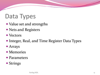
- 17. Verilog HDL 17 Data Types Value set and strengths Nets and Registers Vectors Integer, Real, and Time Register Data Types Arrays Memories Parameters Strings
- 18. Verilog HDL 18 Value Set Verilog concepts to model hardware circuits Value level Value strength Used to accurately model Signal contention MOS devices Dynamic MOS Other low-level details
- 19. Verilog HDL 19 Value level HW Condition 0 Logic zero, false 1 Logic one, true x Unknown z High imp., floating Strength level Type supply Driving strong Driving pull Driving large Storage weak Driving medium Storage small Storage highz High Impedance
- 20. Elements of verilog-logic values 0: zero, logic low, false, ground 1: one, logic high, power X: unknown Z: high impedance, unconnected, tri-state
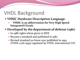
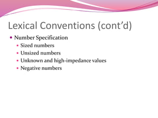
- 21. Elements of verilog- data type Nets Nets are physical connections between devices Many types of nets, but all we care about is wire. Declaring a net wire [<range>] <net_name> ; Range is specified as [MSb:LSb]. Default is one bit wide Registers Implicit storage-holds its value until a new value is assigned to it. Register type is denoted by reg. Declaring a register reg [<range>] <reg_name>; Parameters are not variables, they are constants.
- 22. Verilog Primitives Basic logic gates only and or not buf xor nand nor xnor bufif1, bufif0 notif1, notif0
- 23. Numbers in Verilog <size>’<radix> <value> 8’h ax = 1010xxxx 12’o 3zx7 = 011zzzxxx111 No of bits Binary b or B Octal o or O Decimal d or D Hexadecimal h or H Consecutive chars 0-f, x, z
- 24. Logical Operators && logical AND || logical OR ! logical NOT Operands evaluated to ONE bit value: 0, 1 or x Result is ONE bit value: 0, 1 or x A = 1; A && B 1 && 0 0 B = 0; A || !B 1 || 1 1 C = x; C || B x || 0 x but C&&B=0
- 25. Bitwise Operators (i) & bitwise AND | bitwise OR ~ bitwise NOT ^ bitwise XOR ~^ or ^~ bitwise XNOR Operation on bit by bit basis
- 26. Bitwise Operators (ii)c = ~a; c = a & b; a = 4’b1010; b = 4’b1100; a = 4’b1010; b = 2’b11; c = a ^ b;
- 27. >> shift right << shift left a = 4’b1010; d = a >> 2;// d = 0010,c = a << 1;// c = 0100 cond_expr ? true_expr : false_expr A B Y sel Y = (sel)? A : B; 0 1
- 28. keywords Note : All keywords are defined in lower case Examples : module, endmodule input, output, inout reg, integer, real, time not, and, nand, or, nor, xor parameter begin, end fork, join specify, endspecify
- 29. keywords module – fundamental building block for Verilog designs • Used to construct design hierarchy • Cannot be nested endmodule – ends a module – not a statement => no “;” Module Declaration • module module_name (module_port, module_port, …); • Example: module full_adder (A, B, c_in, c_out, S);
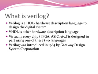
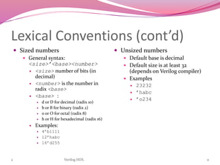
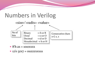
- 30. Verilog keywords Input Declaration • Scalar input list of input identifiers; Example: input A, B, c_in; • Vector input[range] list of input identifiers; Example: input[15:0] A, B, data; Output Declaration • Scalar Example: output c_out, OV, MINUS; • Vector Example: output[7:0] ACC, REG_IN, data_out;
- 31. Types verilog coding Behavioral Procedural code, similar to C programming Little structural detail (except module interconnect) Dataflow Specifies transfer of data between registers Some structural information is available (RTL) Sometimes similar to behavior Structural (gate,switch) Interconnection of simple components Purely structural
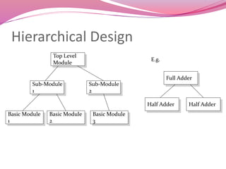
- 32. Hierarchical Design Top Level Module Sub-Module 1 Sub-Module 2 Basic Module 3 Basic Module 2 Basic Module 1 Full Adder Half Adder Half Adder E.g.
- 33. Module f in1 in2 inN out1 out2 outM my_module module my_module(out1, .., inN); output out1, .., outM; input in1, .., inN; .. // declarations .. // description of f (maybe .. // sequential) endmodule Everything you write in Verilog must be inside a module exception: compiler directives
- 34. VHDL coding for AND gate --The IEEE standard 1164 package, declares std_logic, etc. library IEEE; use IEEE.std_logic_1164.all; use IEEE.std_logic_arith.all; use IEEE.std_logic_unsigned.all; ---------------------------------- Entity Declarations ------------------------- entity andgate is Port( A : in std_logic; B : in std_logic; Y : out std_logic ); end andgate; architecture Behavioral of andgate is begin Y<= A and B ; end Behavioral;
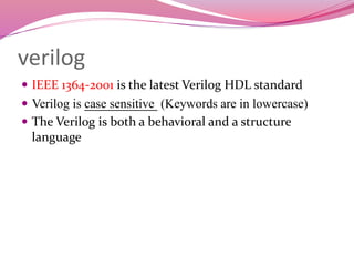
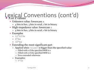
- 35. VERILOG coding for all gate module gates(a, b, y1, y2, y3, y4, y5, y6, y7); input [3:0] a, b; output [3:0] y1, y2, y3, y4, y5, y6, y7; /* Seven different logic gates acting on four bit busses */ assign y1= ~a; // NOT gate assign y2= a & b; // AND gate assign y3= a | b; // OR gate assign y4= ~(a & b); // NAND gate assign y5= ~(a | b); // NOR gate assign y6= a ^ b; // XOR gate assign y7= ~(a ^ b); // XNOR gate endmodule
- 36. Example: Half Adder module half_adder(S, C, A, B); output S, C; input A, B; wire S, C, A, B; assign S = A ^ B; assign C = A & B; endmodule Half Adder A B S C A B S C
- 37. Example: Full Adder module full_adder(sum, cout, in1, in2, cin); output sum, cout; input in1, in2, cin; wire sum, cout, in1, in2, cin; wire I1, I2, I3; half_adder ha1(I1, I2, in1, in2); half_adder ha2(sum, I3, I1, cin); assign cout = I2 || I3; endmodule Instance name Module name Half Adder ha2 A B S C Half Adder 1 ha1 A B S C in1 in2 cin cout sumI1 I2 I3
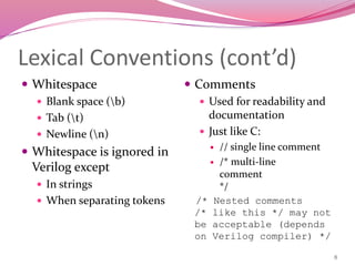
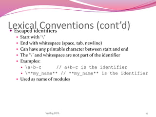
- 38. Example 4-bit adder module add4 (s,c3,ci,a,b) input [3:0] a,b ; // port declarations input ci ; output [3:0] s : // vector output c3 ; wire [2:0] co ; add a0 (co[0], s[0], a[0], b[0], ci) ; add a1 (co[1], s[1], a[1], b[1], co[0]) ; add a2 (co[2], s[2], a[2], b[2], co[1]) ; add a3 (c3, s[3], a[3], b[3], co[2]) ; endmodule a0a1a2a3c3 ci Simpler than VHDL Only Syntactical Difference
- 39. Assignments Continuous assignments assign values to nets (vector and scalar) They are triggered whenever simulation causes the value of the right-hand side to change Keyword “assign” e.g. assign out = in1 & in2; Procedural assignments drive values onto registers (vector and scalar) They Occur within procedures such as always and initial They are triggered when the flow of execution reaches them (like in C) Blocking and Non-Blocking procedural assignments
- 40. Assignments (cont.) Procedural Assignments Blocking assignment statement (= operator) acts much like in traditional programming languages. The whole statement is done before control passes on to the next statement Nonblocking assignment statement (<= operator) evaluates all the right-hand sides for the current time unit and assigns the left-hand sides at the end of the time unit
- 41. Delay Control (#) Expression specifies the time duration between initially encountering the statement and when the statement actually executes. Delay in Procedural Assignments Inter-Statement Delay Intra-Statement Delay For example: Inter-Statement Delay #10 A = A + 1; Intra-Statement Delay A = #10 A + 1; Delay based Timing Control
- 42. Example: Half Adder, 2nd Implementation Assuming: • XOR: 2 t.u. delay • AND: 1 t.u. delay module half_adder(S, C, A, B); output S, C; input A, B; wire S, C, A, B; xor #2 (S, A, B); and #1 (C, A, B); endmodule A B S C
- 43. Combinational Circuit Design Outputs are functions of inputs Examples MUX decoder priority encoder adder comb. circuitsinputs Outputs
- 44. Procedural Statements: if if (expr1) true_stmt1; else if (expr2) true_stmt2; .. else def_stmt; E.g. 4-to-1 mux: module mux4_1(out, in, sel); output out; input [3:0] in; input [1:0] sel; reg out; wire [3:0] in; wire [1:0] sel; always @(in or sel) if (sel == 0) out = in[0]; else if (sel == 1) out = in[1]; else if (sel == 2) out = in[2]; else out = in[3]; endmodule
- 45. Procedural Statements: case case (expr) item_1, .., item_n: stmt1; item_n+1, .., item_m: stmt2; .. default: def_stmt; endcase E.g. 4-to-1 mux: module mux4_1(out, in, sel); output out; input [3:0] in; input [1:0] sel; reg out; wire [3:0] in; wire [1:0] sel; always @(in or sel) case (sel) 0: out = in[0]; 1: out = in[1]; 2: out = in[2]; 3: out = in[3]; endcase endmodule
- 46. Decoder 3-to 8 decoder with an enable control module decoder(o,enb_,sel) ; output [7:0] o ; input enb_ ; input [2:0] sel ; reg [7:0] o ; always @ (enb_ or sel) if(enb_) o = 8'b1111_1111 ; else case(sel) 3'b000 : o = 8'b1111_1110 ; 3'b001 : o = 8'b1111_1101 ; 3'b010 : o = 8'b1111_1011 ; 3'b011 : o = 8'b1111_0111 ; 3'b100 : o = 8'b1110_1111 ; 3'b101 : o = 8'b1101_1111 ; 3'b110 : o = 8'b1011_1111 ; 3'b111 : o = 8'b0111_1111 ; default : o = 8'bx ; endcase endmodule
- 47. – a feedback path – the state of the sequential circuits – the state transition synchronous circuits asynchronous circuits Examples-D latch D flip-flop register Memory elements Combinational circuit Inputs Outputs
- 48. d-Latch,flip-flop module latch (G, D, Q); input G, D; output Q; reg Q; always @(G or D) begin if (G) Q <= D; end endmodule module dff(Q, D, Clk); output Q; input D, Clk; reg Q; wire D, Clk; always @(posedge Clk) Q = D; endmodule
- 49. Jk flip-flopmodule jkff(J, K, clk, Q); input J, K, clk; output Q; reg Q; reg Qm; always @(posedge clk) if(J == 1 && K == 0) Qm <= 1; else if(J == 0 && K == 1) Qm <= 0; else if(J == 1 && K == 1) Qm <= ~Qm; assign Q <= Qm; endmodule
- 50. A counter which runs through counts 0, 1, 2, 4, 9, 10, 5, 6, 8, 7, 0, … Sequence counter module CntSeq(clk, reset, state); parameter n = 4; input clk, reset; output [n-1:0]state; reg1:0]state; [n- integer k; // always @(posedge clk) if(reset) state = 0; else begin case (state) 4'b0000:state = 4'b0001; //0 -> 1 4'b0001:state = 4'b0010; //1 -> 2 4'b0010:state = 4'b0100; //2 -> 4 4'b0100:state = 4'b1001; //4 -> 9 4'b1001:state = 4'b1010; //9 -> 10 4'b1010:state = 4'b0101; //10-> 5 4'b0101:state = 4'b0110; //5 -> 6 4'b0110:state = 4'b1000; //6 -> 8 4'b1000:state = 4'b0111; //8 -> 7 default:state = 4'b0000; endcase end endmodule
- 51. 4-bit Full Adder
- 52. //Gate-level hierarchical description of 4-bit adder module halfadder (S,C,x,y); input x,y; output S,C; //Instantiate primitive gates xor (S,x,y); and (C,x,y); endmodule module fulladder (S,C,x,y,z); input x,y,z; output S,C; wire S1,D1,D2; //Outputs of first XOR and two AND gates //Instantiate the half adders halfadder HA1(S1,D1,x,y), HA2(S,D2,S1,z); or g1(C,D2,D1); endmodule 4-bit Full Adder
- 53. module _4bit_adder (S,C4,A,B,C0); input [3:0] A,B; input C0; output [3:0] S; output C4; wire C1,C2,C3; //Intermediate carries //Instantiate the full adder fulladder FA0 (S[0],C1,A[0],B[0],C0), FA1 (S[1],C2,A[1],B[1],C1), FA2 (S[2],C3,A[2],B[2],C2), FA3 (S[3],C4,A[3],B[3],C3); endmodule 4-bit Full Adder
- 54. 2 to 4 Decoder
- 55. //Gate-level description of a 2-to-4-line decoder module decoder_gl (A,B,E,D); input A,B,E; output[0:3]D; wire Anot,Bnot,Enot; not n1 (Anot,A), n2 (Bnot,B), n3 (Enot,E); nand n4 (D[0],Anot,Bnot,Enot), n5 (D[1],Anot,B,Enot), n6 (D[2],A,Bnot,Enot), n7 (D[3],A,B,Enot); endmodule 2 to 4 Decoder
- 56. Behavioral Modeling (2) The procedural assignment statements inside the always block are executed every time there is a change in any of the variable listed after the @ symbol. (Note that there is no “;” at the end of always statement) //Behavioral description of 2-to-1-line multiplexer module mux2x1_bh(A,B,select,OUT); input A,B,select; output OUT; reg OUT; always @(select or A or B) if (select == 1) OUT = A; else OUT = B; endmodule
- 57. Behavioral Modeling (3) 4-to-1 line multiplexer
- 58. Behavioral Modeling (4) //Behavioral description of 4-to-1 line mux module mux4x1_bh (i0,i1,i2,i3,select,y); input i0,i1,i2,i3; input [1:0] select; output y; reg y; always @(i0 or i1 or i2 or i3 or select) case (select) 2'b00: y = i0; 2'b01: y = i1; 2'b10: y = i2; 2'b11: y = i3; endcase endmodule
- 59. Flip-Flops and Latches module D_latch(Q,D,control); output Q; input D,control; reg Q; always @(control or D) if(control) Q = D; //Same as: if(control=1) endmodule
- 60. Flip-Flops and Latches //D flip-flop module D_FF (Q,D,CLK); output Q; input D,CLK; reg Q; always @(posedge CLK) Q = D; endmodule //D flip-flop with asynchronous reset. module DFF (Q,D,CLK,RST); output Q; input D,CLK,RST; reg Q; always @(posedge CLK or negedge RST) if (~RST) Q = 1'b0; // Same as: if (RST = 0) else Q = D; endmodule
- 61. T & J-K Flip-Flops //T flip-flop from D flip-flop and gates module TFF (Q,T,CLK,RST); output Q; input T,CLK,RST; wire DT; assign DT = Q ^ T ; //Instantiate the D flip-flop DFF TF1 (Q,DT,CLK,RST); endmodule //JK flip-flop from D flip-flop and gates module JKFF (Q,J,K,CLK,RST); output Q; input J,K,CLK,RST; wire JK; assign JK = (J & ~Q) | (~K & Q); //Instantiate D flipflop DFF JK1 (Q,JK,CLK,RST); endmodule flop-flipJKafor'')1( flop-flipTafor)1( QKJQtQ TQtQ Characteristic equations of the flip-flops:
- 62. Sequence Recognizer Identify the sequence 1101, regardless of where it occurs in a longer sequence.
- 64. Sequence Recognizer module seq_recognizer(CLK,RST,X,Z); input CLK,RST,X; output Z; reg [1:0]state, next_state; parameter A=2’b00,B=2’b01,C=2’b10,D=2’b11; reg Z; always@(posedge CLK or posedge RST) begin if(RST==1) state <= A; else state <= next_state; end
- 65. always@(X or state) begin case(state) A:if(X)next_state <= B; else next_state <= A; B:if(X)next_state <= C; else next_state <= A; C:if(X)next_state <= C; else next_state <= D; D:if(X)next_state <= B; else next_state <= A; endcase end always@(X or state) begin case(state) A:Z<=0; B:Z<=0; C:Z<=0; D:Z<=X?1:0; endcase end endmodule