


![List of Figures
1.1. WLAN with one access point ............................................................................ 3
1.2. Mobidot network with a centralized management system ........................................ 9
2.1. Centralized architecture [Webopedia1] ...............................................................17
2.2. Star architecture [Webopedia1] .........................................................................18
2.3. Bus architecture [Webopedia1] .........................................................................18
2.4. Decentralized architecture [Minar2002] ..............................................................18
2.5. Mesh architecture [Webopedia1] .......................................................................19
2.6. Hierarchical architecture [Minar2002] ................................................................19
2.7. Ring architecture [Minar2002] ..........................................................................19
2.8. Centralized+Ring architecture [Minar2002] .........................................................20
2.9. Centralized+Centralized architecture [Minar2002] ................................................20
2.10. Centralized+Decentralized architecture [Minar2002] ...........................................21
2.11. Tree architecture [Webopedia1] .......................................................................21
2.12. Mobidot Infrastructure Situation 1 ...................................................................25
2.13. Mobidot Infrastructure Situation 2 ...................................................................26
2.14. Mobidot Infrastructure Situation 3 ...................................................................27
2.15. Involved systems, their dependencies and responsible actors .................................28
2.16. Use case diagram group 1 ...............................................................................29
2.17. Use case diagram group 2 ...............................................................................30
2.18. Sequence diagram for use case: CreateNewAccount ............................................31
2.19. Sequence diagram for use case: CreateNewAccount (part 2) .................................32
2.20. Sequence diagram for use case: ManageFirmware (add) .......................................34
2.21. Sequence diagram for use case: ManageFirmware (add, part 2) .............................35
2.22. Sequence diagram for use case: ManageHotspotsAndAPs (view) ...........................36
2.23. Sequence diagram for use case: ManageHotspotsAndAPs (view, part 2) ..................36
2.24. Sequence diagram for use case: ManageConfigurations (edit) ................................37
2.25. Sequence diagram for use case: ManageConfigurations (edit, part 2) ......................37
2.26. Sequence diagram for use case: ManageAccounts (delete) ....................................38
2.27. Sequence diagram for use case: ManageAccounts (delete, part 2) ...........................39
2.28. The data model ............................................................................................43
3.1. Subsystem class diagram .................................................................................49
3.2. Deployment diagram .......................................................................................51
3.3. UserManagementModels class diagram ..............................................................53
3.4. UserManagementGUI class diagram ..................................................................55
3.5. UserManagementControllers class diagram .........................................................56
3.6. ConfigurationStoreSubsystem class diagram ........................................................56
4.1. 802.1X authentication process [Open1X1] ..........................................................65
4.2. Netgear WG602 access point [SeattleWireless1] ..................................................68
4.3. Netgear WG602 access point (internal view) [SeattleWireless1] ..............................68
4.4. Linksys WRT54G access point + router [SeattleWireless2] ....................................69
4.5. Linksys WRT54G access point + router (internal view) [SeattleWireless2] ................70
4.6. Soekris net4801 [Soekris3] ...............................................................................71
4.7. Soekris net4801 (internal view) [Soekris3] ..........................................................71
4.8. SSH tunneling ...............................................................................................79
C.1. OSI reference model [Tanenbaum1996] ........................................................... 112
vii](https://image.slidesharecdn.com/designhotspot-141130130021-conversion-gate01/85/Design-hotspot-With-Opensource-Tools-7-320.jpg)
![C.2. TCP/IP and OSI network stacks [Tanenbaum1996] ............................................ 114
viii](https://image.slidesharecdn.com/designhotspot-141130130021-conversion-gate01/85/Design-hotspot-With-Opensource-Tools-8-320.jpg)


![1.1.2. Project Description
Design an appropriate model for the network architecture of a hotspot. All problems described
above should be solved with this model. In more detail this means using OSS and budget hardware
to achieve compatibility and cost reduction. Develop a prototype of the network architecture and of
a management system that will monitor and manage this architecture.
1.2. The problem domain
Around 1995, connectivity (with connectivity in this document is meant: having the possibility to
connect to some public computing network such as the Internet) wasn't part of common life. People
used to communicate with one another by means of letters, telegraphy and telephone. With the intro-duction
of computers this gradually changed. First some computers were connected to create a net-work
called ArpaNet, initiated by American military and educational institutions. Later on, in the
nineties, the Internet was formed out of the former ArpaNet, connecting computers to each other
worldwide, creating a huge network of computers. The Internet introduced connectivity to the home.
Anyone with a desktop computer at home was able to connect to anyone else by the Internet, in a
matter of minutes. Nowadays, there is again a shift in the field of connectivity. It's not just possible
for anyone to connect to the worldwide network, it is possible for anyone to do this from anywhere,
and at any time. With the introduction of technologies such as GPRS, UMTS, and Wi-Fi
(Wireless-Fidelity), mobile access to the Internet has become possible. The last of these technolo-gies,
Wi-Fi (also known as WLAN), will form the basis for this project.
1.2.1. What is Wireless-Fidelity?
"How many times have you needed network or Internet access at home and
wished you could work in a different room, or even outside, without having to run
a long Ethernet cable? How many times have you been in a public spot, such as an
airport or hotel, and realized you needed to send a quick e-mail? How many hours
have you wasted sitting in conference rooms between meetings while your e-mails
pile up?" [Roshan2003]
Wireless Fidelity is a relatively new technology which enables people to connect to IP networks
(such as the Internet) without any network wires connected to their computer. Wireless digital com-munication
is not new, other wireless technologies such as HAM-radio and Aloha have been around
for a long period. There were several reasons why these technologies didn't become popular: they
were expensive, they were not easy to use (mainly used by specialized individuals and enthusiasts)
and they offered a much lower bandwidth compared to wired networks. This all changed with the
introduction of Wireless Fidelity (or Wi-Fi).
Wi-Fi can operate in two modes: infrastructure mode and ad hoc mode. Ad hoc mode (referred to as
IBSS, or Independent Basic Service Set) refers to direct connections between exactly two com-puters,
with the same possibilities as a serial cable. Infrastructure mode is the more interesting mode
of Wi-Fi: it basically works the same as an ethernet, without using network wires. This mode is
what the name WLAN (Wireless Local Area Network) refers to.
2](https://image.slidesharecdn.com/designhotspot-141130130021-conversion-gate01/85/Design-hotspot-With-Opensource-Tools-12-320.jpg)
![Figure 1.1. WLAN with one access point
In this mode, several computers can be interconnected, in order to exchange information and data,
just like you would on a wired network. One computer in the network could even be designated to
be a gateway machine, enabling any computer on the network to access an outside network such as
the Internet. In the infrastructure mode, there is a central component, called the access point. Infra-structure
mode is also referred to as BSS (Basic Service Set). When multiple access points are used
to create one WLAN, this mode is called ESS (Extended Service Set). All computers that wish to
have a wireless network connection (from now on called wireless clients), associate (make a con-nection
and authenticate) with this access point. This can only be done when the device with Wi-Fi
capable hardware is in the range of the access point, which is limited to 300 meters outdoors, and at
most 100 meters indoors (depending on the amount of walls that are in between the wireless client
and the access point). Once a connection with the access point is established, the wireless client can
begin performing network operations, just like in a wired network. And just like on a wired network,
clients of wireless networks will have to share the available bandwidth. Wi-Fi introduces advant-ages,
some of which include the fact that wires are no longer needed to interconnect all computers of
a network. Furthermore, anyone with a portable computer with Wi-Fi capable hardware can connect
be part anywhere in the coverage area of the access point and access the local network and possibly
also external networks.
Wi-Fi is defined in one of IEEE's standards: 802.11.
"802.11 refers to a family of specifications developed by the IEEE for wireless
LAN technology. 802.11 specifies an over-the-air interface between a wireless cli-ent
and a base station or between two wireless clients. The IEEE accepted the spe-cification
in 1997." [Webopedia2]
3](https://image.slidesharecdn.com/designhotspot-141130130021-conversion-gate01/85/Design-hotspot-With-Opensource-Tools-13-320.jpg)

![This way of Internet connection sharing more or less lead to another new approach, which was im-plemented
mostly by students in some student cities, including Leiden in the Netherlands (see
[WirelessLeiden1]) and Seattle in the United States (see [SeattleWireless3]). In this case, access to a
certain access point would be freely and publicly available. To denote an area which had coverage
of a publicly accessible access point, the term hotspot was introduced (in most cases, a spot is con-sidered
to be an infinitely small dot, or at least too small to be a circle or oval. In this case, a hotspot
refers to the coverage area of an access point which has a radius of 100 up to 300 meters. Normally
this would be called a circle, but in comparison to the size of the already existing Internet, this cov-erage
area is indeed very small, and thus called a spot). But this wasn't all, all these hotspots would
be interconnected using the same air-to-air interface or possibly some using wires. This would cre-ate
a giant LAN (Local Area Network) which introduced the possibility of creating a socialist-type
of network: sharing data (music, movies, games, etc) free of charge. This would be very interesting,
as it wouldn't be needed to connect to the Internet to find any music or movies. And it would lead to
some advantages, such as not incurring high bandwidth costs of normal Internet connections and
having a smaller possibility of the file sharing connections being tapped by authorities, risking pen-alties
for copyright infringement, etc. Anyone with a laptop would be able to make sure he would be
in the coverage area of a hotspot, connect to the network and start sharing data.
Like with all good ideas, it didn't take long before a commercial implementation was given birth. It
was soon realized that there was a need for Internet access (for business people, students, etc) out-side
home, business or university. Some time after a failed start up by Mobistar in the 90's (using the
original 802.11 standard), some small parties, called WISPs (Wireless Internet Service Providers),
started installing access points (using the 802.11b standard) at public meeting places, such as cafes,
restaurants, hotels, libraries, etc. The term hotspot would from then on refer to a public place that
implemented a publicly accessible wireless network. The access point would be connected to the In-ternet
using either an existing Internet connection, or a new Internet connection would be acquired.
Furthermore, the access to the wireless network wouldn't be free of charge, but would be charged
for, by the hotel, restaurant, etc. in question. With the introduction of such commercially accessible
hotspots, interesting opportunities became possible. It would be possible to place hotspots in restaur-ants
along highways which are used a lot by business people. These business people would then be
able to make a stop over between one appointment and another at such a restaurant, and be able to
check their email, enter information into a corporate system about the last appointment, etc. Or it
would be possible to equip hotels with publicly accessible access points, and enable business people
staying over at that hotel for a conference to perform tasks that otherwise would have to wait until
these people would return from the conference.
This commercial approach started small. Most large companies are usually hesitant to take the first
steps in a completely new market, in which successful involvement is uncertain. This meant that
several small parties first started initiatives, slowly implementing more and more public places with
hotspots. Once the business gains were recognized by large corporations (mostly telecommunication
providers), these corporations would buy out the small WISPs, to take over their market share, and
start expanding from that point on. A good example of this in the Netherlands was Hubhop, which
was initiated in May 2002, and by May 2003 was bought by KPN, the largest telecommunication
provider of the Netherlands.
The buyout of small WISPs by large corporations meant the initiation of a widespread implementa-tion
of public hotspots. At this moment, there are three major parties (and some minor parties) in the
Netherlands offering Internet access over public hotspots: KPN Hubhop, T-Mobile and Swisscom
Eurospot, and each of these parties is independently implementing public hotspots.
5](https://image.slidesharecdn.com/designhotspot-141130130021-conversion-gate01/85/Design-hotspot-With-Opensource-Tools-15-320.jpg)
![1.2.3. The problems that we are trying to solve
We observe that the Wi-Fi world is fragmented, possibly because Wi-Fi is still an immature techno-logy.
We see home user systems being backed by large corporations such as Linksys (daughter com-pany
of Cisco). For public hotspot systems we however see no systems from large corporations. No-madix,
which is rather expensive (in terms of investments for managers of public institutions which
house the public hotspots), is not backed by some large corporation. It has such a dangerous market
position, perhaps even more because their systems are quite expensive. In short, there's little to
choose from in the world of public hotspot systems. It would be nice to see a more diverse set of
systems available, of which this project perhaps could be one. For example, when we look at sys-tems
for cellular communication, why do Motorola, Siemens, Nokia and Ericsson all develop mo-bile
phones? The technology they provide is not renewing (compared amongst each other), the com-ponents
used for the transmissions are quite standard. Their approach to certain usability problems
or features however differs greatly. This is where they've got something to gain. The same goes for
the world of systems for public hotspots. While the core technology doesn't differ at all between sys-tems
(we do want to maintain interoperability, at least the end user expects this), there are possibilit-ies
for new systems by focusing on different features and problems. This however is only a market-ing
problem/observation.
We will now go into more depth as to which technical (and sometimes technical and economical)
problems exist. Basically, the problem that we observe is that there's no system that's extensible to a
large degree, that supports SNAT circumvention (i.e. adjustments needed in existing infrastructure
in order to support management and monitoring of devices), supports zero configuration and which
is low cost.
SNAT circumvention
This plays a role with networking hardware, in the IP layer of the TCP/IP stack, where hardware
used in a network is placed behind a NAT-gateway. Before we can fully understand what the prob-lem
is, we first need to look at what NAT actually is.
"Network Address Translation (NAT) allows computers on a private network to
access the Internet without requiring their own global (public) Internet address.
NAT modifies outgoing network packets so that the return address is a valid Inter-net
host. Return (incoming) packets have their destination address changed back,
and are relayed to the client host, thereby protecting the private addresses from
public view." [MLIP1]
Network Address Translation is usually applied in order to perform Internet Connection Sharing:
sharing one Internet connection with multiple clients on an internal network. Since normally each
network client should be configured with its own unique IP address, we would run into a problem:
the number of external IP addresses that are in possession of a certain person are usually less than
the amount of network clients. In order to solve this, the network clients get a private IP address as-signed,
an IP address that is not recognized on public networks such as the Internet, it has to be
translated to the public IP address of the network gateway (the gateway between the local network
and the Internet). When replies of traffic (initiated by a local network client) arrive at the gateway,
the destination IP address of the reply is translated back to the private IP address of the respective
local network client, and the packet is forwarded to that network client. Two forms of address trans-lation
exist:
6](https://image.slidesharecdn.com/designhotspot-141130130021-conversion-gate01/85/Design-hotspot-With-Opensource-Tools-16-320.jpg)

![even more) be interested in wireless access. The situation even gets worse due to the fact of the ex-istence
of multiple, non-interoperable, WISPs, as will be discussed below. All these costs might lead
to a too uncertain return-on-investment, meaning businesses won't invest.
Furthermore, there are two problems which in itself don't make the project renewing, but do need to
be addressed in this project:
Extensibility
This isn't a problem that plays a role in competitive systems such as Nomadix, but it does need to be
taken into account if a system is to be created which can last. Even though performance is sacri-ficed,
extensibility is needed to keep up with the fast development in the world of Wi-Fi. It basically
means the entire system should be extensible, i.e. all different parts of the system. Even extensibility
in other directions have to be taken into account, for example: can the system that is created be run
on different hardware? If the Nomadix system would only run on the current selected set of hard-ware,
they would have a problem when that certain piece of hardware is not available anymore.
Roaming
Each WISP implements the authentication of its users (checking whether a certain user is allowed to
use the services of the network) in its own way, which makes roaming difficult. "Roaming is a gen-eral
term in wireless telecommunications that refers to the extending of connectivity service in a net-work
that is different from the network with which a station is registered. The canonical example of
'roaming' is for cellular phones, when you take your phone to an area where your service provider
does not have coverage (e.g., another country). In order for a mobile device to roam to another net-work,
a number of processes need to be performed. The first necessity for inter-network roaming is
that your service provider must have a roaming agreement with the network to which you have
moved. In 802.11 roaming can also mean subscriber mobility or handover within the same network"
[Wikipedia9]. This means that users are unable to roam to the networks of other WISPs. When, for
example, some hotels are equipped with T-Mobile hotspots and some others with KPN hotspots,
then a client who has a KPN Wi-Fi subscription will be forced to find a hotel room in a hotel which
equips a KPN hotspot, while his preference for a certain hotel might force him into a hotel which
equips T-Mobile hotspots. This might be a problem for certain businesses, which already have a
public hotspot, but not with multiple WISPs. Since roaming in many cases is not possible, it would
be needed to pay for wireless access more than once, i.e. getting a Wi-Fi subscription with more
than one WISP. This is a inconvenience for the user. Clients of for example hotels and restaurants
will be more selective. Previously they would select a hotel by its ranking and perhaps its location.
Now they will also take into account if they can have access to the network of their WISP. This
might result into a drop of clients for certain hotels. The problem with roaming is mainly in combin-ation
with the large investment costs. Roaming partnerships, such as Picopoint and Boingo do exist,
but these equip expensive hardware and partnership costs as discussed above, and as such the roam-ing
problem is not solved.
1.3. Project goal
The goal is to design and implement a prototype of the mentioned network architecture, in order to
facilitate a solution to the mentioned problem. This will be done using OSS and budget hardware.
Some important requirements of this network include user friendliness, scalability, flexibility, com-patibility,
robustness and low production costs.
8](https://image.slidesharecdn.com/designhotspot-141130130021-conversion-gate01/85/Design-hotspot-With-Opensource-Tools-18-320.jpg)

![area of the hotspot has a radius of several kilometers.
1.6.2. Conventions
In this document, references made to other documentation and quotations from other documentation
will be denoted by square brackets ('[' and ']') with an identification tag inside that is formed of the
author's name, the year in which the document was published (if known) and possibly an integer to
denote a sequence if multiple documents exist of the same author and publishing year. Further, not
yet defined terms will be defined in-line in the respective document section (as opposed to the use of
footnotes, which are unfortunately not supported fully, as described in appendix C.1). Lastly,
whenever references in third person are made, the word 'he' is used, in each of these cases 'she' could
be meant just as well, unless stated otherwise.
1.7. Document outline
This document discusses the thesis project 'Design and implementation of a hotspot network' from
inception to completion. It starts with an introduction, in which the problem domain is discussed,
followed by a discussion of the project's goal and approach.
The document then discusses the various phases of the project, namely the analysis, design, imple-mentation
and testing phases. Each chapter will tell about the approach taken to finish a phase. Fur-thermore
it discusses the choices that were made as multiple options appeared. There are four
chapters discussing the various phases, the analysis chapter (chapter 2), which discusses the require-ments
elicitation and the determination of the actors and use cases, the design chapter (chapter 3) the
implementation chapter (chapter 4) and finally the evaluation chapter (chapter 5).
Finally, in the conclusions the results of the project and some interpretations of these results will be
given. The conclusions will also include a general discussion of the study as it was provided by the
TU Delft and how it was perceived by the writer of this document.
11](https://image.slidesharecdn.com/designhotspot-141130130021-conversion-gate01/85/Design-hotspot-With-Opensource-Tools-21-320.jpg)


![identification of the various actors and uses of the system (in terms of scenarios and use cases) from
the requirements is discussed, followed by a discussion of the inception of the data model from the
use cases.
2.2.1. Network topologies
The theory of network topologies is actually based on graph theory of mathematics. Many similarit-ies
can be found, and also many algorithms from graph theory are used in network applications that
apply a particular topology.
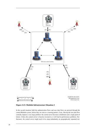
When we are talking about network structures and topologies in relation to the objective of this
project, there are actually two distinct network structures to talk about. The first one is the network
that is formed by the various hotspots and a central Mobidot system, in this document this network
will be referred to as Mobidot network. The other one is the network that is formed between mul-tiple
access points at one location (a hotel, a train station, etc), this network type will be referred to
as 'Mobidot WLAN'. Multiple access points are used when the coverage area of one access point is
too small, or when the bandwidth offered by one access point is too small for the amount of custom-ers
that want access to the network.
Before having an in-depth look at each of the network topologies, first lets have a look a what kinds
of network topologies there are in general. [Webopedia1] states:
"Topology refers to the shape of a network, or the network's layout. How different
nodes in a network are connected to each other and how they communicate is de-termined
by the network's topology. Topologies are either physical or logical."
According to [Minar2002] there are four basic topologies: centralized, decentralized, hierarchical
and ring systems. These topologies can be used by themselves or they can be combined in one way
or another to create hybrid networks. [Minar2002] considers topology in terms of the information
flow. This means that the information flow that occurs between nodes more or less defines with
what kind of network topology we are dealing. Because of this fact we will later on have a look at
what kinds of information flows exist within the Mobidot network, in order to be able to choose a
network structure.
Centralized architecture
In a centralized architecture, client machines
have to contact a central server in order to get
something done.
Figure 2.1. Centralized architecture
17](https://image.slidesharecdn.com/designhotspot-141130130021-conversion-gate01/85/Design-hotspot-With-Opensource-Tools-27-320.jpg)
![[Webopedia1]
Figure 2.2. Star architecture
[Webopedia1]
Star architecture
The star architecture is a member of the central-ized
architectures group, and is realized as a net-work
which contains a central hub and several
nodes. All nodes (can only) communicate to
each other through the central hub.
Bus architecture
In the bus architecture, nodes are connected to
one another through a common bus. This archi-tecture
is a special kind of centralized architec-ture,
since it's not merely the fact that there can
be nodes that play a centralized role in the net-work,
but more the fact that the backbone
through which the nodes communicate is the
centralized part of the network.
Figure 2.3. Bus architecture
[Webopedia1]
Figure 2.4. Decentralized architecture
[Minar2002]
Decentralized architecture
Decentralized systems are essentially pure peer-to-
peer systems, thus there is symmetrical com-munication
(one node can request something
from another and get a response, that other node
can also request something from the former
node, and get a response also), and all nodes
have equal roles. There is no central part in the
network, and as such, the availability of the net-work
is not dependent on one single machine,
while this is an advantage, pure decentralized
systems also introduce the problem that there is
no central authority.
18](https://image.slidesharecdn.com/designhotspot-141130130021-conversion-gate01/85/Design-hotspot-With-Opensource-Tools-28-320.jpg)
![Mesh architecture
The mesh architecture is a concept that comes
from graph theory, and denotes a network in
which all nodes are connected to all other nodes.
Figure 2.5. Mesh architecture
[Webopedia1]
Figure 2.6. Hierarchical architecture
[Minar2002]
Hierarchical architecture
One of the systems that made the Internet ac-cessible
to humans is the Domain Name Service
(accessible in the meaning that it is relatively
easy to operate). The Domain Name Service (or
DNS) is a hierarchical system "where authority
flows from the root name-servers to the server
for the registered name and often down to third-level
servers" [Minar2002].
Ring architecture
"A single centralized server
cannot handle high client load,
so a common solution is to use
a cluster of machines arranged
in a ring to act as a distributed
server. Communication
between the nodes coordinates
state-sharing, producing a
group of nodes that provide
identical function but have
19](https://image.slidesharecdn.com/designhotspot-141130130021-conversion-gate01/85/Design-hotspot-With-Opensource-Tools-29-320.jpg)
![fail-over and load-balancing
capabilities." [Minar2002]
Figure 2.7. Ring architecture
[Minar2002]
Figure 2.8. Centralized+Ring
architecture [Minar2002]
Hybrid: centralized+ring architecture
"Serious web server applica-tions
often have a ring of serv-ers
for load balancing and fail-over.
The server system itself
is a ring, but the system as a
whole (including the clients) is
a hybrid: a centralized system
where the server is itself a
ring. The result is the simpli-city
of a centralized system
(from the client's point of
view) with the robustness of a
ring." [Minar2002]
Hybrid: centralized+centralized architecture
In situations where servers themselves are clients
to other servers, we are talking about a central-ized+
centralized architecture. For instance 2-tier
and multi-tier applications work this way.
Figure 2.9. Centralized+Centralized
architecture [Minar2002]
Hybrid: centralized+decentralized architec-ture
"A new wave of peer-to-peer
systems is advancing an archi-
20](https://image.slidesharecdn.com/designhotspot-141130130021-conversion-gate01/85/Design-hotspot-With-Opensource-Tools-30-320.jpg)
![Figure 2.10. Centralized+Decentralized
architecture [Minar2002]
tecture of centralized systems
embedded in decentralized
systems. This hybrid topology
is realized with hundreds of
thousands of peers in the
FastTrack file-sharing system
used in KaZaA and Morpheus.
Most peers have a centralized
relationship to a "super node,"
forwarding all file queries to
this server (much like a Nap-ster
client sends queries to the
Napster server). But instead of
super nodes being standalone
servers, they band themselves
together in a Gnutella-like de-centralized
network, propagat-ing
queries. Internet email also
shows this kind of hybrid topo-logy.
Mail clients have a cent-ralized
relationship with a spe-cific
mail server, but mail serv-ers
themselves share email in a
decentralized fashion."
[Minar2002]
Hybrid: tree architecture
"A hybrid topology. Groups of
star-configured networks are
connected to a linear bus back-bone."
[Webopedia1]
Figure 2.11. Tree architecture
[Webopedia1]
2.2.1.1. Evaluation properties for choosing network topologies
21](https://image.slidesharecdn.com/designhotspot-141130130021-conversion-gate01/85/Design-hotspot-With-Opensource-Tools-31-320.jpg)
![[Minar2002] presents seven properties which can influence decisions in choosing a certain network
topology. Whenever a new application is designed, one of the design steps includes the choice of a
suitable topology, based on the requirements of the application that is to be developed. These seven
properties (as presented by [Minar2002]) are:
• Manageability
Manageability defines if it is easy to manage the system. Management activities could include
updating, repairing and logging.
• Information coherence
Coherence is defined by Dictionary.com as:
"The quality or state of cohering, especially a logical, orderly, and aesthetically
consistent relationship of parts."
So when we are talking about information coherence, we are talking about pieces of information
throughout the system, which have to be or naturally are consistent with each other. In this docu-ment,
when a system is said to be coherent, it means information coherence exists in the system,
or can be enforced without problems. When talking about information coherence, three aspects
play a role: non-repudiation, auditability and consistency. Non-repudiation means that it is not
possible for people to send information through the system and later on deny that they sent it.
Auditability means that transactions through the system are traceable to an origin. Consistency
deals with the fact that certain pieces of information shouldn't contradict with certain other
pieces of information in the system. When these aspects are either enforced or readily available
by nature within the system, then we are dealing with a system in which information is coherent.
Information in a system is said to be not coherent when it is impossible to enforce information
coherence without changing the network topology used.
• Extensibility
Extensibility deals with the fact how well a certain system can be extended with resources (as in
information or other data). For example, how easy is it to add a host sharing some files to an ex-isting
file sharing network?
• Fault tolerance
Fault tolerance concerns the immunity of the system to erroneous situations or faults. The more
fault tolerant a system is, the more a system can continue to operate without having the user no-tice
a fault occurred.
• Security
Security deals with how easy it is to hack the system, or seen from the other viewpoint, how
hard it is to secure the system.
• Resistance to lawsuits and politics
Is the system easy to shutdown by authorities, for example in media sharing applications? Being
lawsuit proof mainly plays a role in popular peer-to-peer file sharing applications, which are un-der
pressure of large music and movie production companies.
22](https://image.slidesharecdn.com/designhotspot-141130130021-conversion-gate01/85/Design-hotspot-With-Opensource-Tools-32-320.jpg)
![• Scalability
Scalability is about being able to enlarge a system to meet demands. It deals with how well the
network scales when resources are actually being added to the network. For example can a cer-tain
network handle 2000 clients or hosts, or can it only handle 10 clients?
Of these seven properties, resistance to lawsuits, extensibility and information coherence will not be
reviewed. Resistance to lawsuits doesn't play any role in the choice of network topologies for a cer-tain
business application. And since the Mobidot network is not destined to be an information sys-tem,
but rather a network access providing system, it won't be dealing with information and as such
extensibility and information coherence don't play a role in this case.
2.2.1.2. Evaluation of the various network topologies
In order to ease the choice of a network topology, these properties are valued against each network
topology set forth by [Minar2002] and [Webopedia1] with a 'good', 'average' or 'bad' designation.
Each network topology will be discussed individually, all properties will get a grade depending on
the results of the discussion and a summarizing table will be provided at the end of this section.
2.2.1.2.1. Centralized architectures
In centralized architectures, there is one central server to which many clients connect. The fact that
there is only one server in the system, means that the system is easily manageable, all data is con-centrated
at one host and as such only one host needs to be managed. Securing a centralized system
is very easy, there is only one host that needs to be protected. Fault tolerance is not achieved in any
way in a centralized system. If the central Mobidot system goes down, the network is down, causing
the entire system to be unusable. When talking about scalability there are little growing possibilities
of the system (hardware might be added, but only a limited amount) without changing the network
topology used, thus the scalability of centralized systems is bad.
2.2.1.2.2. Ring architectures
Ring architectures are architectures which consist of multiple servers. Since these servers usually
have a single owner, these networks act the same as centralized architectures when it comes to man-ageability
and security. One of the added advantages of ring architectures over centralized architec-tures
is the fact that there is fault tolerance, since multiple servers are doing exactly the same thing.
This first of all achieves load balancing, but it also creates the possibility of letting other servers
take over the work of a certain server if it goes down, resulting in fault tolerance. Lastly, contrary to
centralized architectures, ring architectures scale quite well if well-designed, any number of hosts
can be inserted into the ring.
2.2.1.2.3. Hierarchical architectures
Hierarchical systems have a clear chain of actions, but usually are owned by various people, making
it hard to manage individual hosts of the network. Since nodes in the network usually are owned by
multiple individuals, incorporating security into the system is hard. Contrary to centralized architec-tures,
hierarchical architectures provide good scalability. On any level of the tree below the root, any
number of servers can be added in order to handle the system load. Finally, hierarchical systems are
more fault tolerant than centralized systems, but the root of the hierarchical architecture is still a
single point of failure.
23](https://image.slidesharecdn.com/designhotspot-141130130021-conversion-gate01/85/Design-hotspot-With-Opensource-Tools-33-320.jpg)
![2.2.1.2.4. Decentralized architectures
Decentralized systems consist of multiple systems, which all form an active part of the network.
Usually the various hosts in the network are owned by various individuals, making the system hard
to manage. Further, for the same reason, a decentralized system is hard to secure. Any host could
connect and start to inject bad information or data into the system, because of the fact that there is
no central authority. But contrary to centralized systems, decentralized systems are very fault toler-ant,
since in essence all nodes are equals, it won't be noticed if one node goes down, since others can
take over. Lastly, a decentralized system scales quite well when information coherence is not con-sidered,
any number of hosts can be connected without performance degradation (any node that con-nects
to the network can from then on provide the same services to the network to again other nodes,
and these nodes in turn can do the same) If it would be necessary to keep the information in the sys-tem
coherent, algorithms would be needed to achieve this, causing a lot of overhead. "If that over-head
grows with the size of the system, then the system may not scale well." [Minar2002]. Since in-formation
doesn't play a role in the Mobidot network, information coherence doesn't have to be con-sidered,
causing decentralized architectures to scale quite well in that particular situation.
2.2.1.2.5. Hybrid architectures
It is impossible to discuss the properties of all possible combinations of architectures, so only a gen-eral
overview will be presented here.
Combining different architectures, creating hybrid architectures, is usually done to add the advant-ages
of one architecture to those of another, trying to get the best of both worlds. For example file
sharing applications like Kazaa utilize a hybrid centralized + decentralized architecture. Having a
couple of super nodes form a decentralized network, and having this network of super nodes acting
as a centralized system to many clients. This gives advantages like manageability of the system,
ability to keep the system secure (in essence the super nodes are central and in control of one party),
but still the system has the very good fault tolerance of decentralized systems.
2.2.1.2.6. Summary of the evaluation properties
Below are presented the evaluation properties as defined and discussed for the various topologies
above.
Name Manageability Fault tolerance Security Scalability
Centralized good bad good bad
Decentralized bad good bad good
Hierarchical average average bad good
Ring good average good average
Table 2.1. Evaluation properties for several network topologies
2.2.1.3. The appropriate topology
A problem with the system that is to be designed is the fact that the system has a distributed nature,
which makes things more complex. On one hand there are the access points which have to be mon-
24](https://image.slidesharecdn.com/designhotspot-141130130021-conversion-gate01/85/Design-hotspot-With-Opensource-Tools-34-320.jpg)


![activation code.
6. [The HotspotVisitor uses the external pay-ment
system, which generates and stores an
activation code and announces this code to
the HotspotVisitor. The activation code
(including some extra information, such as
the amount that was paid for) is stored in
the Mobidot database by the external pay-ment
system.]
7. The HotspotVisitor enters personal inform-ation
(name, postal address and email ad-dress),
a new user name and password, and
the activation code into the input form on
the "create new account" web page and hits
the "Create Account" button.
8. The central Mobidot system checks in the
Mobidot database whether this user name is
available.
9. The central Mobidot system receives the re-quest,
checks whether the activation code is
correct by contacting the Mobidot database.
When it is, the central Mobidot system re-trieves
some additional information from
the same table in the Mobidot database (i.e.
the amount that was paid for).
Exit condition
10. The HotspotVisitor's account is created in
the Mobidot database. The HotspotVisitor
receives a message confirming the success-ful
creation of the account.
Table 2.2. Use case CreateNewAccount
Figure 2.18. Sequence diagram for use case: CreateNewAccount
31](https://image.slidesharecdn.com/designhotspot-141130130021-conversion-gate01/85/Design-hotspot-With-Opensource-Tools-41-320.jpg)


![cilities for the user to identify himself to the sys-tem.
ExternalCommSubsystem The ExternalCommSubsystem is responsible for
communication with external systems, such as an
external payment system which generates activa-tion
codes. This subsystem will be used both by
the subsystems of the central management sys-tem
and of the AP. It will be part of the central
Mobidot system, as that eases the implementa-tion
of the system.
Figure 3.2. Deployment diagram
Note: subsystems denoted with square brackets ('[' and ']') will be implemented in this project, but
cannot be modeled in UML. Subsystems denoted with angle brackets ('<' and '>') will be implemen-ted
using existing software packages.
3.3.4. Persistent data management
For the persistent data management it was necessary to choose an appropriate storage back end for
storing several types of information. For most types of information the MySQL database is found to
be the best choice, mainly due to its speed, its ease of implementation (no custom storage structure
has to be defined, only a set of attributes per information type has to be defined), its ability to easily
execute complex queries and finally its ability to easily support concurrent accesses.
UserStoreSubsystem The UserStoreSubsystem is responsible for stor-ing
user related data (i.e. the list of UserAc-counts
which are collected in the UserAccount-
Collection).
RoamingPartnerStoreSubsystem The RoamingPartnerStoreSubsystem is respons-ible
for storing the list of ExternalWifiProviders
(RoamingPartnersCollection) with which Mo-bidot
has a roaming agreement.
HotspotStoreSubsystem The HotspotStoreSubsystem is responsible for
storing hotspot related data (the list of Hotspots
and APs in HotspotCollection).
51](https://image.slidesharecdn.com/designhotspot-141130130021-conversion-gate01/85/Design-hotspot-With-Opensource-Tools-61-320.jpg)


![4.1.3. Security
"It's depressing how often we see that those who don't remember history are
doomed to repeat it. When cordless phones and the first analog cell phones hit the
market, anybody with a scanner that operated at the right frequency could easily
listen to calls not intended for them. The same cycle played out with 802.11
equipment." [Gast2002]
The above quotation already gives some clue about the problems with security in wireless networks.
At first it turned out that wireless networks weren't secure at all, no thought had ever been given to
security while the IEEE 802.11 standard was being devised.
"While the current access points provide several security mechanisms, our work
combined with the work of others show that ALL of these mechanisms are com-pletely
in-effective." [Arbaugh2001]
A lot of security mechanisms exist for 802.11 networks, but, as pointed out above, most fail in ac-complishing
their goal. Some of the security mechanisms have no or little effect or have a huge
management overhead, some of them make the network more insecure then before deployment of
the security mechanism, and some of them might only be usable to a certain degree.
There are several tasks that have to/can be performed on a wireless network in order to make it
(more) secure:
• Authentication:
"Authentication is any process by which you verify that someone is who they
claim they to be. This usually involves a user name and a password, but can in-clude
any other method of demonstrating identity, such as a smart card, retina
scan, voice recognition, or fingerprints. Authentication is equivalent to showing
your drivers license at the ticket counter at the airport." [Apache1]
• Authorization:
"Authorization is finding out if the person, once identified, is permitted to have
the resource. This is usually determined by finding out if that person is a part of a
particular group, if that person has paid admission, or has a particular level of se-curity
clearance. Authorization is equivalent to checking the guest list at an ex-clusive
party, or checking for your ticket when you go to the opera." [Apache1]
• Access control:
"Access control is a much more general way of talking about controlling access to
a web resource. Access can be granted or denied based on a wide variety of criter-ia,
such as the network address of the client, the time of day, the phase of the
moon, or the browser which the visitor is using. Access control is analogous to
locking the gate at closing time, or only letting people onto the ride who are more
than 48 inches tall - it's controlling entrance by some arbitrary condition which
may or may not have anything to do with the attributes of the particular visitor."
60](https://image.slidesharecdn.com/designhotspot-141130130021-conversion-gate01/85/Design-hotspot-With-Opensource-Tools-70-320.jpg)
![[Apache1]
• Key management: Key management relates to the ease of the management of keys used in cryp-tographic
algorithms. The easier it is to change any keys that are in use, the better the key man-agement
is.
• Data integrity and confidentiality: Data integrity and confidentiality relates to the protection of
data that travels across the network. It has to be protected from tampering (integrity protection)
and from eavesdropping (confidentiality).
These concepts will play an important role in determining whether a certain security measure is ap-propriate
or not. The distinction between authentication and access control is not always very clear,
but for the sake of this project we will refer to authentication as the process whereby a user gets ac-cepted/
rejected by a certain system on the basis of personal non-shared information, such as a user
name-password combination. When a shared secret is involved, we will refer to it as access control.
The goal of this discussion is not to go into implementation details of the security mechanisms, but
merely to give an overview of what is available to secure the Mobidot WLAN, present weaknesses
of each and find the best candidate to do the job.
4.1.3.1. Service Set Identifier (Closed Network Access Control)
Initially, the Service Set Identifier was meant to identify a network. The access point would broad-cast
its name to the surrounding area using beacon frames. A beacon frame is similar to the beacon
signals used in aviation, by which a pilot can determine whether he is close to an airport, and which
one that would be. The same goes for beacon frames in Wi-Fi: a beacon frame is transmitted by an
access point and carries information about that access point such as the name of the network (SSID),
a time stamp, supported transfer rates, etc. Such a beacon frame is periodically sent by the access
point (by default the interval is set to 100ms), in order to make it possible for wireless clients to find
the access point and associate with it. In other words: the beacon frame is the heartbeat of a wireless
LAN. Similar as in aviation where a airport would seem to have disappeared if there would be a
power outage, an access point would be offline (and thus invisible for radio receivers) if such a
beacon frame would not be broadcast for one reason or another. (See [Geier2002] for more informa-tion
on beacon frames.) The use of beacon frames makes it easy for people to select the right net-work
by just scanning for them. Lucent came up with a security mechanism called Closed Network
Access Control which changed the network name into a shared secret, by not having the access
point broadcast its network name. This means that only people who know the SSID are able to con-nect.
It is false to assume this approach makes the network safe. In order for a client to connect to an
access point, he still has to connect to the access point of the network he intends to connect to,
meaning he should send along the SSID of the network he wishes to connect to, and this means that
the SSID is still sent in clear text. People with the right equipment will be able to sniff such packets
from the air, and find out the SSID. This security measure should be treated as stated by
[Dismukes2002]:
"SSID settings on your network should be considered the first level security, and
should be treated as such. In its standards-adherent state, SSID may not offer any
protection to who gains access to your network, but configuring your SSID to
something not easily guessable can make it harder for intruders to know what ex-actly
they are looking at."
61](https://image.slidesharecdn.com/designhotspot-141130130021-conversion-gate01/85/Design-hotspot-With-Opensource-Tools-71-320.jpg)
![For Mobidot it's not a good choice to implement Closed Network Access Control as it makes it
harder for people to connect to the Mobidot WLAN, while one of the main goals of the system is the
ease of making connections.
4.1.3.2. Access control lists (MAC address filtering)
Each network card (both wireless and wired) is configured with a MAC address. A MAC address is
an address in the form of 6 bytes which identifies a specific network card on a network. All MAC
addresses are unique, this is accomplished by dividing the MAC address space into several chunks,
each chunk getting assigned to a specific vendor. MAC address filtering is based on the identifica-tion
by their MAC address. A list of MAC addresses of allowed clients makes it possible to provide
access only to those hosts that are mentioned on the list. This would seem like a good security
mechanism, if it wouldn't be the case that MAC addresses can be overridden ('spoofed') by software.
This means that one could sniff wireless traffic for accepted MAC addresses, and spoof traffic with
any valid MAC address found. Another problem of MAC address filtering is the fact that it incurs a
large management overhead, since the list of MAC addresses has to be managed by hand. For small
networks this might be no problem, but for large networks (such as the Mobidot infrastructure aims
to be) this is not feasible.
4.1.3.3. Open system authentication
Open system authentication actually is a situation in which there is no authentication, it is the de-fault
authentication protocol for 802.11. Simply any client that connects to the access point is al-lowed
access. This might seem a strange sort of security, but it enables the possibility of disabling
faulty simple authentication systems, and then, for example, enabling more sophisticated authentica-tion
schemes such as 802.1X.
4.1.3.4. WEP/WEP+/128-bit WEP and shared key authentication
WEP (Wired Equivalent Privacy) is a security mechanism that was devised in order to make wire-less
networks more secure (in a wired-equivalent way). WEP has three security goals
[Borisov2001]:
• Confidentiality: The fundamental goal of WEP is to prevent casual eavesdropping.
• Access control: A second goal of the protocol is to protect access to a wireless network infra-structure.
The 802.11 standard includes an optional feature to discard all packets that are not
properly encrypted using WEP, and manufacturers advertise the ability of WEP to provide ac-cess
control.
• Data integrity: A related goal is to prevent tampering with transmitted messages; the integrity
checksum field is included for this purpose.
[Borisov2001] has shown that WEP fails to achieve all three goals. WEP encryption is achieved by
combining a shared secret key with an initialization vector. The first problem lies in the fact that the
size of the initialization is limited in size to 24 bits, making brute force attacks (attacks in which all
possible combinations are tried) feasible (the entire space of 24 bits can be used up in less than half
a day with average traffic, resulting in a wrap around of the initialization vectors), this problem is
referred to as key stream reuse. [Borisov2001] notes that this problem of key stream reuse is inevit-able.
The 802.11 specification recommends against initialization vector reuse, but doesn't prohibit it.
62](https://image.slidesharecdn.com/designhotspot-141130130021-conversion-gate01/85/Design-hotspot-With-Opensource-Tools-72-320.jpg)
![This means hardware implementations should accept reused initialization vectors, or risk non-interoperability
with 802.11 standard compliant devices.
Furthermore, there are certain vectors which are cryptographically weak, which means that the WEP
key can be cracked more easily when such initialization vectors are used. Another problem with the
initialization vectors is that some hardware always initializes to 0 when being reset, resulting a high-er
frequency of certain initialization vectors than others. Lucent has designed in reaction to these ini-tialization
vector problems WEP+, or 128-bit WEP as they call it, as an enhancement of standard
WEP which uses only 40 bit keys. But this doesn't solve the problem, since the problem is not the
key that was used, but the initialization vector. The use of larger keys only makes the amount of
bandwidth that can be used smaller, since it takes more CPU cycles to encrypt the traffic, and thus
less traffic can be sent or received per second.
4.1.3.5. Broadcast key rotation
This is an idea introduced by Cisco, and it is related to WEP. Normally, all traffic on the network
would be encrypted using the same key. With broadcast key rotation, the access point utilizes a dif-ferent
key for broadcast packets, such as DHCP. These broadcast keys are also short lived, typically
10 minutes or so. The effect of this is that an attacker cannot collect enough packets to crack the
WEP key, but the security mechanism is only applicable to broadcast traffic, and not to specific user
data traffic. Since this is an idea that was introduced by Cisco, it is proprietary and not widely im-plemented
and used, and as such it is not quite usable.
4.1.3.6. 802.1X (EAP, or Extensible Authentication Protocol)
In the new standard 802.11i (which will be discussed later on), 802.1X plays an important role, as it
takes care of the authentication of users. The new standard 802.11i has not been finalized yet, but
802.1X has already been implemented into 802.11 products in order to already take advantage of it.
802.1X is:
"Port-based network access control that makes use of the physical access charac-teristics
of IEEE 802 LAN infrastructures in order to provide a means of authen-ticating
and authorizing devices attached to a LAN port that has point-to-point
connection characteristics, and of preventing access to that port in cases in which
the authentication and authorization fails. A port in this context is a single point of
attachment to the LAN infrastructure." [802.1X-2001]
802.1X uses EAP (Extensible Authentication Protocol), which is a transport protocol, which is op-timized
for authentication purposes. As the name already shows, it is an extensible protocol, in fact,
no authentication methods are defined by EAP, such methods still have to be defined. Many of such
EAP methods exist:
• EAP-MD5: authentication mechanism which uses an MD5 (Message Digest version 5) hash of
user name and password in order to authenticate the user. According to [Dismukes2002] EAP-MD5
offers no key management, requiring the use of static WEP keys. This completely disables
the enhanced security possibilities of EAP.
• L(ightweight)EAP: LEAP or EAP-Cisco Wireless uses the same approach as EAP-MD5 except
for the fact that it uses dynamic WEP keys, which are rotated quite often (making it near to im-possible
to crack the WEP key). Furthermore it adds the possibility of mutual authentication, in
63](https://image.slidesharecdn.com/designhotspot-141130130021-conversion-gate01/85/Design-hotspot-With-Opensource-Tools-73-320.jpg)
![which the client is able to know if a certain access point is authentic. This prevents people from
placing rogue access points into the wireless network. Two problems exist with LEAP, one of
them being the fact that LEAP is designed by Cisco, resulting in only Cisco hardware being able
to use LEAP. The other problem is the fact that MS-CHAPv1 is used for authentication (both
ways), which has known vulnerabilities.
• EAP-TLS: EAP-TLS utilizes Transport Layer Security (IETF's standardization of SSL or Secure
Socket Layers) for authentication. Instead of user name/password combinations, this system uses
X.509 certificates to handle authentication. The difference between the two is that the former
method sends personal secret information (a password), while the latter method is able to identi-fy
an entity (a user or a system) without sending private information. This is achieved by having
a trusted third party sign such a certificate. The entity checking the identity of his peer can then
check if the signature of the trusted third party is real. If this is the case, then the trusted third
party certifies that the public personal information really identifies the entity that owns the certi-ficate.
Several problems exist with this approach. The first problem is the fact that Microsoft de-veloped
this security mechanism, resulting in a situation where this mechanism only works on
Microsoft products. Replacing any software in the tool chain by another equivalent software will
result in a non-working system (For example if you use OpenLDAP as directory service instead
of Active Directory). Another problem is the fact that a public key infrastructure is used, which
is a concept that is quite unknown to most companies, resulting in either a steep learning curve,
or giving up upon EAP-TLS. Yet another problem is the fact that Microsoft utilizes custom at-tributes
in the certificates that are used by EAP-TLS, while those fields are not added to certific-ates
which are issued by Verisign or Thawte. This means that only certificates issued by Mi-crosoft
can be used.
• EAP-T(unneled)TLS: EAP-TTLS was design by Funk Software in response to EAP-TLS. EAP-TTLS
provides for mutual authentication, but only for AP to client authentication certificates are
used. For client to AP authentication, user credentials (user name/password) are used. EAP-TTLS
can pass the user credentials using any challenge-response mechanism specified by the
administrator. (PAP (PPP Authentication Protocol), CHAP (Challenge Handshake Authentica-tion
Protocol), MS-CHAPv1 (Microsoft CHAP version 1), MS-CHAPv2 (Microsoft CHAP ver-sion
2), PAP/Token Card, EAP)
• P(rotected)EAP: according to [Dismukes2002], PEAP has the same characteristics as EAP-TTLS,
except for the fact that it is designed by Microsoft and Cisco instead of Funk Software.
There are lots more implementations of methods for EAP, for a complete list, refer to [IANA1].
64](https://image.slidesharecdn.com/designhotspot-141130130021-conversion-gate01/85/Design-hotspot-With-Opensource-Tools-74-320.jpg)
![Figure 4.1. 802.1X authentication process [Open1X1]
"IEEE 802.1x is a port based authentication protocol. It can be used in *any*
scenario where one can abstract out the notion of a port. It requires entities to play
three roles in the authentication process: that of a supplicant, an authenticator and
an authentication server. A Port Access Entity (PAE) is an entity that has access
or is capable of gaining or controlling access to some port which offers some ser-vices.
When applied to IEEE 802.11, the access point acts as an authenticator,
while a wireless station (laptop etc) is the supplicant which is authenticated by the
authentication server (for example a certain RADIUS implementation)."
[Open1X1]
802.1X wasn't specifically designed for use on wireless networks, but for wired networks. It has
been ported to wireless networks because of the fact it is extensible, easing the process of adding
more authentication mechanisms (based on EAP) later on to wireless products. The use of EAP on
wireless networks does however introduce a problem: since it was designed for wired networks, no
real thought has been given to the possibility of people sniffing the EAP traffic. In the case of wired
networks it is quite hard to sniff such traffic, it involves having access to the network devices of ma-chines
involved (the server in question, or routers in between). In the case of wireless networks it is
much easier to sniff network traffic, it can be achieved by just putting up a wireless receiver, and see
all network traffic flow by. But, as [Gast2002] states, EAP is still a far better solution to the current
802.11 security problems than WEP ever was. According to [Airespace1] 802.1X introduces the
possibility of having a master key sent to the user in encrypted form (after the user has been authen-ticated,
the key will be sent along with the message that tells the user the authentication process was
a success), which from then on will be used for communication purposes. When 802.1X is used by
itself, this means that the master key will be the key that will be used for the WEP protocol.
4.1.3.7. 802.11i, WPA (TSN, TKIP) and WPA2 (RSN, CCMP, AES-CCM)
802.11i is the new security standard for 802.11 networks devised by IEEE. As already stated before,
802.1X will play an important role in 802.11i, as it takes care of the authentication. The 802.11i
standard has not been finalized yet. 802.11i will provide for an authentication framework
65](https://image.slidesharecdn.com/designhotspot-141130130021-conversion-gate01/85/Design-hotspot-With-Opensource-Tools-75-320.jpg)
![(802.1X/EAP) combined with any authentication algorithm (which doesn't get mandated by the
802.11i standard). Further, 802.11i will provide for enhanced key management, dynamic keys, mu-tual
authentication and for data privacy and integrity. Data privacy and data integrity will be
provided for in two ways:
• TKIP: this will use per-frame keying (changing keys after every frame sent) and MIC (message
integrity check). TKIP will be compatible with old hardware, since it uses the same encryption
protocol as WEP (RC4), but as stated before, it will use a new key for every packet. Further, it
will encrypt the initialization vector, which in case of WEP is sent in the clear (which is a secur-ity
hole in the WEP case).
• AES-CCM: the approach for new hardware will be based on the AES algorithm. The Advanced
Encryption Standard is the new American government's encryption standard of choice. AES is
based on the Rijndael algorithm which was developed by the Belgian researchers Vincent Rij-men
and Joan Daemen. Details of the Rijndael algorithm aren't needed here, except for the fact
that AES replaces DES because of its greater strength and speed (that is, AES is faster than
Triple DES. Triple DES is basically DES, but run three times. This was done to achieve a
stronger encryption while no better alternative was available yet. See [AESLounge1] for more
information).
Because industry couldn't wait for the release of 802.11i, the Wi-Fi Alliance (which is a non-profit
international association formed in 1999 to certify interoperability of wireless Local Area Network
products based on IEEE 802.11 specification) felt obliged to release a "snapshot" of the 802.11i
standard, based on draft 3 of the 802.11i standard [Strand2004]. As stated by [Strand2004], the Wi-
Fi Alliance released the snapshot as WPA (Wi-Fi Protected Access) or TSN or "Transition Security
Network". TSN is based on TKIP + 802.1X. The final version of the 802.11i standard will be called
WPA2 by the Wi-Fi Alliance or RSN ("Robust Secure Network"). RSN will be based on CCMP +
802.1X. According to [Airespace1], WPA2 will introduce some advanced features, including key
management, by having a pairwise master key (PMK) which is exchanged using 802.1X or in a pre-shared
way, which will be used to generate/retrieve a pairwise transient key (PTK), which in turn
will be used to generate three other keys for respectively key exchange and transport of data: key
confirmation key (KCK), key encryption key (KEK) and the temporal key (TK). Other advanced
features include pre authentication, which authenticates a wireless client to other access points to
which the user might move in the future, thus enabling roaming.
4.1.3.8. VPN
A VPN, or Virtual Private Network is:
"A private network that utilizes parts of the public telecommunications network.
VPNs send encrypted data through the public network to ensure the security of
transactions" [hp1]
VPNs make it possible to circumvent certain security problems of wireless networks, even though
they weren't designed for that purpose. With VPNs, as stated above, one can create a virtual network
on top of an existing network structure, such as the Internet, and usually this is done in a secure way
using an encryption algorithm. While using VPNs for authentication, data integrity and confidential-ity
protection is quite secure, it still doesn't address all security problems. A problem that remains to
exist is the fact that two illegitimate persons can still abuse the wireless network, though not for ac-
66](https://image.slidesharecdn.com/designhotspot-141130130021-conversion-gate01/85/Design-hotspot-With-Opensource-Tools-76-320.jpg)

![4.1.4.1.1.1. Netgear
Figure 4.2. Netgear WG602 access point [SeattleWireless1]
Netgear is one of very few companies to supply the source code of the software used in their hard-ware
products. Since the software used by Netgear is GPL licensed, they are forced to publish the
source code of the modifications they made to the original GPL software.
Specifications of the WG602 model include, according to [SeattleWireless1]: 16 megabytes of
RAM, 4 megabytes of flash memory, an Intersil 54g miniPCI (PCI with small slots) card with Pris-mGT
chipset, a RTL8139 chipset, and a processor operating at 100 up to 150 MHz.
Figure 4.3. Netgear WG602 access point (internal view) [SeattleWireless1]
68](https://image.slidesharecdn.com/designhotspot-141130130021-conversion-gate01/85/Design-hotspot-With-Opensource-Tools-78-320.jpg)
![The first version of the WG602 has a miniPCI slot, which makes it possible to apply hardware up-grades
to the WG602 in order to support new Wi-Fi standards such as 802.11i. It is, however, un-known
if new versions and other models also have a miniPCI slot (it seems to be a trend to integrate
the Wi-Fi chipset into the used motherboard, in order to force the user into buying new hardware
when he desires to use new technologies). The operating system kernel in use is Linux 2.2.14, which
is quite old, but seems to do the job. Furthermore, several other operating system tools, utilities and
daemons are used: busybox 0.50, uClibc 0.9.08, vsftpd 1.1.3. When considering finances, Netgear is
quite interesting, with prices ranging from 60 to 200 euros. [Tweakers1]
4.1.4.1.1.2. Linksys
Figure 4.4. Linksys WRT54G access point + router [SeattleWireless2]
Linksys is one of the other few companies that uses GPL'ed software in its products, and as such
provides the used source code on its website. The specifications, according to [SeattleWireless2], of
the Linksys WRT54G seem to be better than the WG602 model of Netgear in several aspects.
69](https://image.slidesharecdn.com/designhotspot-141130130021-conversion-gate01/85/Design-hotspot-With-Opensource-Tools-79-320.jpg)
![Figure 4.5. Linksys WRT54G access point + router (internal view)
[SeattleWireless2]
While the amount of memory and flash memory are the same (16 MB respectively 4 MB), the pro-cessor
operates at a speed of 200 MHz, and uses Broadcom chipsets for both wired and Wi-Fi net-working.
Old versions of the WRT54G had a miniPCI slot, which made it possible to apply hard-ware
upgrades to the WRT54G in order to support new Wi-Fi standards such as 802.11i. In the
latest versions however, this miniPCI slot has been removed and replaced with a chipset which has
been integrated into the motherboard, as such disabling the possibility of easy future upgrades. The
Linksys WRT54G also uses a Linux kernel, but a slightly newer (but not quite up to date) one, ver-sion
2.4.20. A lot more tools and libraries are used by the WRT54G than the WG602. They both use
uClibc and busybox, but WRT54G also uses other tools and libraries such as: iproute2, openssl,
pppd, pptp-client, rp-pppoe, rp-l2tp, udhcpd (which are all popular Linux tools) and even a small
sized HTTP daemon. Linksys, like Netgear, has quite interesting solutions when looking at the
prices, which range from 50 to 200 euros. [Tweakers1]
4.1.4.1.2. Solution using separate hardware parts
Another solution for the hardware implementation is to make use of several separate computer parts,
such as a motherboard, CPU, memory and networking devices, in order to create an access point
from the ground up.
4.1.4.1.2.1. Soekris board with additional hardware
70](https://image.slidesharecdn.com/designhotspot-141130130021-conversion-gate01/85/Design-hotspot-With-Opensource-Tools-80-320.jpg)
![Figure 4.6. Soekris net4801 [Soekris3]
"Soekris Engineering, Inc. is a small company specializing in the design of em-bedded
computer and communication devices." [Soekris1]
As stated, Soekris Engineering specializes in the design of embedded systems.
Figure 4.7. Soekris net4801 (internal view) [Soekris3]
The embedded systems are composed of a motherboard with CPU (486-class or 586-class), ethernet
ports for wired network connectivity, a miniPCI slot and up to two PCMCIA (small credit card-sized
devices) adapters which might enable the embedded system to be expanded with a wireless
network card or any other device, some other hardware chipsets and some specific amount of
memory and flash memory (the amount depends on the model chosen).
71](https://image.slidesharecdn.com/designhotspot-141130130021-conversion-gate01/85/Design-hotspot-With-Opensource-Tools-81-320.jpg)
![The reasons that make this solution very interesting are the following:
• The motherboard has a hardware watchdog integrated. "A watchdog is a device used to protect a
system from specific software or hardware failures that may cause the system to stop respond-ing.
The application is first registered with the watchdog device. Once the watchdog is running
on your system the application must periodically send information to the watchdog device. If the
device doesn't receive this signal within the set period of time it would execute the proper key-strokes
to reboot the machine or restart the application." [Webopedia7]
• The motherboard has lots of expansion options, it supports up to three expansion slots (miniPCI
and 2 PC-Card/Cardbus slots). As such the embedded system can be expanded with hardware
that increases the high availability even further. Further, when new Wi-Fi standards get devised,
the old Wi-Fi miniPCI card can simply be replaced with a new one.
What might make this system less interesting is its price. The base embedded system costs between
130 and 280 dollars (without discounts), depending on what is needed for processing power and
amount of expansion slots, etc. [Soekris2] In order to make this into an access point, at least one
miniPCI Wi-Fi card is needed, and the choice is quite limited due to the limited availability of
drivers in Linux. An Atheros based card which is 802.11i ready is available for around 80 dollars.
[Netgate1]
4.1.4.1.3. The chosen hardware solution
The Linksys customizable access point has been chosen as the hardware device of preference. The
Linksys seems to offer a quite good price/capabilities ratio. Furthermore, there seem to be quite
some firmware available for the Linksys, which seems to show that a lot of people are already modi-fying
their access points. This could mean that a lot of documentation is already available, which
could ease the implementation quite a lot.
4.1.4.2. Firmware / Build root
In this section we will look at the firmware that is available for the Linksys WRT54G access point.
4.1.4.2.1. The original Linksys firmware
It was quickly found that the original Linksys firmware build root is poorly designed. The most
probable reason for this is probably that Linksys has nothing to gain from a well-designed build
root, they only have man hours to lose. Firmware for future hardware will contain the same software
programs, only the drivers will differ, as new ones will be added in order to support new hardware.
There are several problems with the Linksys build root, one of them being the lack of in-depth docu-mentation.
Only a simple README file could be found, which only describes how to make a binary
firmware. Furthermore, this description isn't even accurate, since the procedure as it is explained
gives errors and the commands entered should be adjusted. On of the largest problems with this
firmware however, is the fact that it is not aimed at extensibility. The build root contains some soft-ware
packages by default, but it doesn't provide easy means for extending the firmware with new
software packages. And even if you would take the time to add (or hack in) these packages, you still
have no mechanism of selecting which packages you want to install, since sometimes you perhaps
want to include different packages than usual, or perhaps leave out some packages of the original
firmware. Lastly, this firmware doesn't include support for a file system that supports persistent stor-age.
The firmware contents are stored in a read only file system, and furthermore only the RAM can
72](https://image.slidesharecdn.com/designhotspot-141130130021-conversion-gate01/85/Design-hotspot-With-Opensource-Tools-82-320.jpg)

![firmware of preference. This is particularly because of the well design (which was developed with
the future in mind, i.e. upcoming modifications, new hardware, etc), and because of the bad design
of the other solutions.
4.1.5. Configuration deployment
It has been chosen to create a set of scripts which can configure the access point to the settings as re-corded
in the management system. These scripts run on first installation of the access point and each
hour to check and possibly perform updates. It has been chosen to have the manager of a public in-stitution
enter the credentials of his Internet connection (user name/password) manually on-site. Due
to the security sensitivity of this information, it is not very wise to store such information centrally
(although taking that approach would reach a full plug-and-play solution). An additional script has
been created that asks for and tests Internet settings using a simple website on a simple web server
which temporarily runs on the access point. The manager of a public institution will use his browser
to visit this website to enter his credentials.
4.1.6. Maintenance and monitoring
One particularly difficult problem to deal with is making the access points manageable from any-where.
This means it should be possible to place the access point at any node in some network, but
still be able to manage and monitor this access point from an external network, such as the Internet.
The particular problem which we are dealing with was described in the design problems, section
'Maintenance and monitoring', namely the fact that most networks use Network Address Translation
(NAT). In such cases we can modify firewalling rules at an already existing firewall, this is however
not what we want. We want to solve the problem in such a way that at most only a very minimal
change to existing systems and configurations is needed. About the only way of achieving this is by
the use of a VPN (Virtual Private Network) solution. VPNs are essentially tunnels through existing
networks which connect nodes logically which are by far not directly physically connected. With
some solutions this can be done with encryption. Before discussing the chosen solution for this
problem, we'll first look at some well known VPN solutions.
4.1.6.1. Network layer
4.1.6.1.1. IP-in-IP tunnels
In some cases, it might be needed to encapsulate IP packets inside other IP packets. In this situation
we are tunneling a network layer network inside another network layer. The most obvious situation
in which this would be applied is a situation where there are two private network layer (IP) net-works,
which are both connected to some public network (the Internet) and which should be connec-ted
together in such a way that it seems to be one private network. This can be achieved using IP-in-
IP tunnels, but the interconnection of networks is also the only thing that is achieved, i.e. there's
no encryption.
4.1.6.1.2. GRE tunnels
GRE stands for Generic Routing Encapsulation and is quite similar to IP-in-IP tunnels, though with
some differences. The first difference is that GRE is a more general approach to network layer in
network layer encapsulation, meaning the encapsulation is not limited to IP, both for the original
packet, and for the packet that encapsulates the original packet. As stated by [RFC1701]:
74](https://image.slidesharecdn.com/designhotspot-141130130021-conversion-gate01/85/Design-hotspot-With-Opensource-Tools-84-320.jpg)
!["In the most general case, a system has a packet that needs to be encapsulated and
routed. We will call this the payload packet. The payload is first encapsulated in a
GRE packet, which possibly also includes a route. The resulting GRE packet can
then be encapsulated in some other protocol and then forwarded. We will call this
outer protocol the delivery protocol."
This more general approach to network layer in network layer encapsulation also creates another
possibility, the transport of special IP packets such as multicast traffic, or even IPv6 packets, but
like IP-in-IP, it also doesn't support encryption.
4.1.6.1.3. Microsoft's PPTP
"PPTP is implemented as a PPP session over Generic Routing Encapsulation
(GRE). Authentication is usually by MSCHAP-v2 (Microsoft Challenge Hand-shake
Authentication Protocol) , and supplies key material for the subsequent Mi-crosoft
Point-to-Point Encryption (MPPE) applied to data packets." [Wikipedia2]
As stated here, PPTP is the encapsulation of PPP in GRE. Recall that GRE is a network layer pro-tocol
and PPP is a data link layer protocol. PPTP is implemented, as already stated earlier, by the
use of the GRE protocol. But in addition to this, a TCP connection from client to server, usually on
port 1723, is used to control the PPTP connection. According to [Hardin2000] and [Wikipedia2]
PPTP suffers security vulnerabilities and as such should not be used.
4.1.6.1.4. L2TP
"L2TP can crudely be described as "PPP over IP", although it has many more fea-tures
than this simple description would imply." [Wikipedia1]
L2TP is based on the older PPTP protocol and the older proprietary L2F (Layer 2 Forwarding) pro-tocol
by Cisco.
"L2TP acts as a data link layer (layer 2 of the OSI model) protocol for tunneling
network traffic between two peers over an existing network (i.e. the Internet). It is
an extension of the Point-to-Point Protocol (PPP). It is still common to use PPP
sessions within an L2TP tunnel. L2TP does not provide confidentiality or strong
authentication itself." [Wikipedia1]
According to [Wikipedia1], L2TP packets can be categorized as two types: control packets and data
packets. Reliability is provided for control packets by the L2TP, but not for the data packets, which
has to be taken care of by higher layer protocols.
4.1.6.1.5. IPSec
All the tunneling protocols discussed up until now don't provide data confidentiality. IPSec on the
other hand is a protocol that does provide confidentiality, and even more. IPSec, as the name already
says, secures IP traffic, and it works on the network layer. The IPSec protocol provides four func-tions:
• Confidentiality. Confidentiality is achieved by means of encryption. IPSec is a framework of
75](https://image.slidesharecdn.com/designhotspot-141130130021-conversion-gate01/85/Design-hotspot-With-Opensource-Tools-85-320.jpg)
![open standards, which means that it is not bound to any particular encryption algorithm.
• Data integrity. In order to provide data integrity, a hashing algorithm is applied on the messages
that have to be sent out. IPSec uses the Hashed Message Authentication Codes in order to
achieve this, and the most commonly used flavors are HMAC-MD5 and HMAC-SHA1. It is im-portant
to understand that a certain message (of any length) can be converted to a fixed-length
hash, but the reverse, retrieving the message from the hash, isn't possible.
• Origin authentication. Origin authentication is provided and used to make sure the communica-tion
channel is secure. Before any communication can take place, mutual authentication has to
take place.
• Anti replay protection. Anti replay protection works in a similar way to the use of sequence
numbers in TCP. A sequence number gets added to each IPSec packet, and the sequence number
of each packet gets compared to a sliding window. Packages with illegal sequence numbers get
discarded. This prevents illegal uses of IPSec networks, such as rerunning an authentication pro-cess
using sniffed traffic, in order for the hacker to get illegitimate access to the IPSec network,
for example.
Two terms play an important role in IPSec:
• Security Association: A Security Association (SA) is a set of security information that describes
a particular kind of secure connection between one device and another. You can consider it a
"contract", if you will, that specifies the particular security mechanisms that are used for secure
communications between the two. A device's security associations are contained in its Security
Association Database (SAD). [TCPIPGuide2] The to be used security association is identified
by the Security Parameter Index (SPI).
• Security Parameter Index (SPI): A 32-bit number that is chosen to uniquely identify a particular
SA for any connected device. The SPI is placed in AH or ESP datagrams and thus links each se-cure
datagram to the security association. It is used by the recipient of a transmission so it knows
what SA governs the datagram. [TCPIPGuide3]
4.1.6.2. Transport layer
4.1.6.2.1. SSL based VPNs
SSL (Secure Socket Layer; an algorithm with a public-key encryption-based key exchange, certific-ate-
based authentication and symmetric cipher-based traffic encryption) is a technology that adds se-curity
to protocols on the transport layer (mainly TCP). Nowadays it's most commonly used for ser-vices
like HTTP and FTP, in order to make the data transfers secure. The only thing that SSL adds
to an already existing protocol is confidentiality (encryption), it only secures one connection
between two hosts. SSL cannot be used to secure connections between various networks, unless
some custom application is written which implements tunneling of a layer 2 or layer 3 protocol us-ing
SSL for confidentiality. A simple kind of VPN might be implemented by creating a website us-ing
SSL and user logins. After being logged in, the user can access all kinds of data and perform ac-tions,
the only problem with this setup is the fact that it's a remote access based VPN, i.e. it cannot
be used to interconnect networks.
76](https://image.slidesharecdn.com/designhotspot-141130130021-conversion-gate01/85/Design-hotspot-With-Opensource-Tools-86-320.jpg)
![4.1.6.2.2. CIPE
CIPE, which stands for Crypto IP encapsulation, is a custom designed tunneling protocol using en-cryption.
"CIPE encapsulates encrypted IP datagrams in UDP datagrams and sends them via
the normal UDP mechanism. This is different from standard IP-in-IP encapsula-tion.
UDP was chosen because this way many different endpoints can easily be
distinguished by port numbers; because an IP protocol number would warrant a
formal registration; and because handling of UDP datagrams is easier than using a
separate IP protocol number, especially in firewalled setups. Specifically, UDP
can be handled by user-level applications such as a SOCKS5 relayer. A CIPE link
always connects exactly two endpoints." [Titz2004]
As we can read in the above description, CIPE implements the tunnel using UDP, and such a tunnel
can only exist between two end points. As already stated in the description above, the advantage is
that it should be able to pass through the firewall (note: if the firewall doesn't restrict UDP traffic)
without problems, unlike packets using a custom IP protocol, which might be discarded by the fire-wall
with a greater possibility. This advantage only plays a role in networks where a tunnel should
be set up without consent of a security officer. A problem of this approach is the added overhead
and the inability to check for authentication of packets before they are decrypted, which results in a
performance loss in case of denial-of-service attacks. Would it be possible to authenticate packets
before they were decrypted, a denial-of-service attack wouldn't have such a great impact, since the
decryption wouldn't have to take place, which is CPU intensive. Furthermore, a lot of overhead is
added. An IP packet, which already consists of 40 bytes of headers (TCP and IP), gets wrapped in
another UDP/IP packet, which again adds 40 bytes. (UDP, TCP and IP packets all have headers of at
least 40 bytes; there are optional extensions which can make the headers larger)
4.1.6.3. Application layer
4.1.6.3.1. SSH based VPNs
SSH stands for Secure Shell. A shell is a command line user interface which is generally used in
Unix type systems. The secure shell is a secure (and cryptographically strong) implementation of the
old remote shell protocol in UNIX, which enables remote access to UNIX systems. Besides provid-ing
a remote command line interface and authenticate users against a UNIX user database, SSH is
able to perform much more functions, such as forwarding traffic through its encrypted channel. This
makes SSH a popular choice for adding authentication to protocols which natively don't provide au-thentication
or for adding encryption to protocols which natively don't encrypt traffic.
In the case of SSH based VPNs, one protocol or another is tunneled through an existing SSH con-nection.
A popular approach to this is the tunneling of PPP traffic through a SSH connection. It is
actually quite similar to the situation described for SSL VPNs, except for the fact that SSH by
nature is capable of carrying any traffic, i.e. no custom protocol has to be written anymore. Some
problems exist for this approach. First of all, this approach has the same problems when it comes to
overhead and performance loss as the CIPE approach. Furthermore, SSH is a user space program,
which results in two problems. First, the tunnel has to be set up manually (though it could be scrip-ted)
and should always exist in order for the VPN to be usable. Once the tunnel goes down (which
can happen once in a while with TCP connections), the VPN goes down. The second problem is the
fact that SSH lives in user space, meaning a lot of context switches are needed between user and
77](https://image.slidesharecdn.com/designhotspot-141130130021-conversion-gate01/85/Design-hotspot-With-Opensource-Tools-87-320.jpg)
![kernel space: the user wants to connect over the VPN, sets up a connection, this goes from user
space to kernel space, gets routed, gets back to user space to be tunneled through SSH, and then gets
back to kernel space in order to be routed as standard TCP traffic. The same actions (though in op-posite
order) occurs at the other side of the tunnel.
4.1.6.4. The chosen solution
Before we can make a well weighed decision in choosing a tunneling solution, we should first
identify our needs. One need that we can identify is the fact that multiple tunnels per network should
be supported. In [Fratto2000] we can find that IPSec in combination with NAT natively doesn't sup-port
multiple tunnels. The reason for this is actually the same as for any network layer tunneling
solution: we can only identify traffic on the network layer by IP address. Normally in situations with
NAT, traffic is identified by transport layer attributes, such as the source port number. In case of
network layer tunneling, we can only differentiate traffic by the IP address, since the payload of the
network layer packet is not a normal transport layer packet, but a packet of some other type, for ex-ample
GRE. In other words, we can only look at the original source IP address and the translated IP
address in order to know the real destination of incoming tunneled traffic. Due to this fact, all net-work
layer solutions aren't appropriate. In the case of IPSec, it would be possible to differentiate
between various tunnels by the SPI number, as stated by [Fratto2000]. In this case however, we
need specialized hardware, and this is not what we wanted.
This leaves us with transport layer or application layer solutions. In the case of SSL tunnels
however, it was stated we would need to write a custom application in order to implement tunneling
for any type of network traffic. Since this is not at all desired, this leaves us with either SSH tunnel-ing
or CIPE.
First was decided to use PPP over SSH tunnels. PPP is the Point-to-Point Protocol which offers a
layer 2 connection between two end points, which in turn can be used for IP networks and thus also
for TCP and UDP connections. However it turned out also not as a good choice, due to the nature of
TCP connections. In [Titz2001] is extensively explained why this does not work well. It comes
down to problems with the retransmission algorithm used in TCP in case of network congestion. In
such situations, TCP lowers its transmission speed in order to lower the congestion, by increasing
timeouts between the sending of two packets.
78](https://image.slidesharecdn.com/designhotspot-141130130021-conversion-gate01/85/Design-hotspot-With-Opensource-Tools-88-320.jpg)
![Figure 4.8. SSH tunneling
However, when one TCP connection is tunneled through another, this has a very nasty side effect:
"The lower layer TCP queues up a retransmission and increases its timeouts. Since
the connection is blocked for this amount of time, the upper layer (i.e. payload)
TCP won't get a timely ACK, and will also queue a retransmission. Because the
timeout is still less than the lower layer timeout, the upper layer will queue up
more retransmissions faster than the lower layer can process them. This makes the
upper layer connection stall very quickly and every retransmission just adds to the
problem - an internal meltdown effect." [Titz2001]
The upper layer TCP connection is the TCP connection which is tunneled through the lower layer
TCP connection. Due to these problems, another tunneling strategy needed to be chosen. Because
encryption of connections is very desirable, the choice fell on Cipe. Cipe is a relatively new techno-logy
which tunnels IP traffic through UDP tunnels, offering encryption along the way. Unlike other
tunneling protocols like PPTP and IPSec, Cipe, like SSH, can have multiple tunnels through one
NAT-gateway. The tunneling protocol would run in the transport layer, thus it would be possible to
assign it to any given port number (in a 16-bit range), meaning you could theoretically create about
65000 tunnels through one NAT-gateway. This number is enough for Wi-Fi networks, as the
amount of access points at a local site will never be higher than this. It will however quite regularly
be higher than one.
4.1.7. Interoperability
In order to support roaming we will be running an AAA server. We will first investigate which types
of AAA servers are available, followed by an investigation of existing implementations. After that,
we will discuss what AAA server type and implementation was chosen to use.
79](https://image.slidesharecdn.com/designhotspot-141130130021-conversion-gate01/85/Design-hotspot-With-Opensource-Tools-89-320.jpg)
![4.1.7.1. AAA server types
4.1.7.1.1. AAA Servers (Authentication, Authorization and Accounting)
AAA servers play an important role in corporate networks, both business networks and the networks
of Internet Service Providers. AAA servers perform three basic functions: authentication, authoriza-tion
and accounting. Authentication (as already explained earlier) performs verification checks to
see whether the user who tries to log in is who he says he is. Authorization deals with controlling
what someone is allowed to do, which actions that person should be allowed to perform. Finally, ac-counting
takes care of tracking what someone has done, logging which actions a certain user has
performed. According to [Laet2004] The AAA server model was designed in such a flexible way
that (almost) any kind of access method can benefit from its security features: dial up connections,
ISDN, ADSL and VPN. There are three popular implementations of AAA servers. There's RADI-US:
"Remote Authentication Dial-In User Service (RADIUS) is a client/server pro-tocol
and software that enables remote access servers to communicate with a cent-ral
server to authenticate dial-in users and authorize their access to the requested
system or service. RADIUS allows a company to maintain user profiles in a cent-ral
database that all remote servers can share. It provides better security, allowing
a company to set up a policy that can be applied at a single administered network
point. Having a central service also means that it's easier to track usage for billing
and for keeping network statistics. Created by Livingston (now owned by Lucent),
RADIUS is a de facto industry standard used by a number of network product
companies and is a proposed IETF standard." [SearchSecurity1]
Further there's TACACS+, which is Cisco proprietary implementation of an AAA protocol:
"There are three versions of TACACS and the third version is called TACACS+,
which is not compatible with previous versions." [Javvin1]
And finally there's Diameter:
"The Diameter protocol is being designed by the IETF's AAA Working Group."
[OpenDiameter1]
Diameter is a new AAA protocol that's being designed by the IETF as an alternative for the older,
less capable and proprietary RADIUS and TACACS+ protocols.
4.1.7.2. AAA server implementations
4.1.7.2.1. FreeRADIUS
FreeRADIUS is one of a few open source implementations of a RADIUS server. FreeRADIUS
seems to be a quite mature project. FreeRADIUS supports MySQL, PostgreSQL, Oracle and LDAP
databases. It supports EAP and many of its forms: EAP-MD5, EAP-TLS, EAP-TTLS, EAP-PEAP
and EAP-LEAP. It has two very interesting features for Mobidot: it supports executing external pro-grams
(which could make the Mobidot solution support other AAA servers by externally connecting
to such an AAA server, would the AAA server of a roaming partner be of a different type than RA-DIUS),
and it supports proxying of requests (meaning forwarding of the request to another RADIUS
80](https://image.slidesharecdn.com/designhotspot-141130130021-conversion-gate01/85/Design-hotspot-With-Opensource-Tools-90-320.jpg)
![server) with fail-over ("A backup operation that automatically switches to a standby database, server
or network if the primary system fails or is temporarily shut down for servicing" [Webopedia5]) and
load balancing ("Distributing processing and communications activity evenly across a computer net-work
so that no single device is overwhelmed" [Webopedia6]). Finally, the server comes with a
PHP-based web user administration tool. A PAM module (Pluggable Authentication Module) and
Apache web server authentication modules are available. It is stated by the maintainers of FreeRA-DIUS
that the software has reached stable release, and it would be ready for deployment in any size
network.
4.1.7.2.2. Cistron RADIUS, ICRADIUS, XtRADIUS, GNU RADIUS
The Cistron RADIUS server was developed by Miquel van Smoorenburg (from the Cistron ISP in
the Netherlands). The server was developed quite some time ago, and lacks support for new fea-tures.
It does support proxying of requests and PAM authentication, but it doesn't support databases
except for the Berkeley database format DBM and it doesn't support EAP at all, only PAP and
CHAP. ICRADIUS, XtRADIUS and GNU RADIUS are derivatives of Cistron RADIUS, each
adding some minor features. ICRADIUS adds MySQL database support. XtRADIUS adds a quite
nice feature: the ability of running scripts which will handle the authentication and user accounting,
thus enabling querying external resources (much like the external program execution function of
FreeRADIUS). GNU RADIUS adds extensibility by using the Scheme programming language as a
script interpreter, it adds support for PostgreSQL databases and it adds support for SNMP manage-ment
and monitoring.
FreeRADIUS is in fact also another derivative of Cistron RADIUS. But due to the fact that the de-velopment
approach chosen for FreeRADIUS (development done by a large group of individuals),
FreeRADIUS seems to offer much more features and seems to be more mature.
4.1.7.2.3. OpenRADIUS
OpenRADIUS is another implementation of a RADIUS server, which was developed from scratch.
OpenRADIUS doesn't support EAP. On the other hand, OpenRADIUS supports proxying, and is ex-tensible
because of the use of external program calls for the handling of any action, such as authen-tication
of users, etc. For this reason, any type of database could be supported, but isn't at this mo-ment.
OpenRADIUS does introduce an optimizing feature with calling external programs: called
programs are only launched once, and from then on kept in memory, so it can be consulted many
times without needing to reload it, resulting in a performance gain. This project seems to be a one-man
project however, and as such is a less attractive solution than FreeRADIUS.
4.1.7.2.4. tacppd, libtacplus, mod_auth_tacacs
Tacppd is an open source implementation of the Cisco proprietary TACACS+ AAA protocol. The
implementation at this point in time is quite basic, and is mainly limited to operation with Cisco
products. The EAP protocol is not supported, and there's support for one database only: Postgr-eSQL.
Furthermore, it seems like this project is also a one-man project. Tacppd doesn't seem to be a
real alternative to the use of a RADIUS server, also because of the fact that TACACS+ is a propriet-ary
protocol. Tacppd does come with some useful additions however: libtacplus and
mod_auth_tacacs. The first of these is a code library with which TACACS+ authentication calls can
be made or received easily. The last of these is an authentication module for use in the Apache web
server.
81](https://image.slidesharecdn.com/designhotspot-141130130021-conversion-gate01/85/Design-hotspot-With-Opensource-Tools-91-320.jpg)


![Appendix A. References
A.1. Books
• Networking in general
1. [Dyson1994] Peter Dyson - Dictionary of networking
The Network Press, 1994, 2nd edition
ISBN 0-7821-1818-6
2. [Tanenbaum1996] Andrew S. Tanenbaum - Computer Networks
Prentice Hall, Inc, 1996, 3rd edition
ISBN 0-13-394248-1
• Security
1. [Laet2004] Gert de Laet and Gert Schauwers - Network Security Fundamentals
Cisco Press, Sep. 2004
ISBN 1-587051672
2. [Lubbe1997] J.C.A. van der Lubbe - Basismethoden cryptografie
Delftse Universitaire Pers, 1997, Tweede druk
ISBN 90-407-1256-5
• Wi-Fi
1. [Roshan2003] Pejman Roshan and Jonathan Leary - 802.11 Wireless LAN Fundamentals
Cisco Press, Dec. 2003
ISBN 1-58705-077-3
• Various
1. [Franssen2002] Maarten Franssen - Methodologie en Ethiek van de Techniek
TUDelft Fac. TBM, sectie Filosofie, Maart 2002
A.2. Articles and other documents
95](https://image.slidesharecdn.com/designhotspot-141130130021-conversion-gate01/85/Design-hotspot-With-Opensource-Tools-105-320.jpg)
![• Network structures
1. [Epema2003] DHJ Epema - Distributed Systems
Course IN4002 on http://blackboard.icto.tudelft.nl, file book2003.pdf
2. [Minar2002] Nelson Minar - Distributed Systems Topologies
http://www.openp2p.com/pub/a/p2p/2001/12/14/topologies_one.html
http://www.openp2p.com/pub/a/p2p/2002/01/08/p2p_topologies_pt2.html
• Wi-Fi
1. [Register1] The Register - Will pressure to speed up 802.11n wreck standards process?
http://www.theregister.co.uk/2004/01/16/will_pressure_to_speed_up/
2. [Wifinetnews1] Wi-Fi Networking News - 802.11n Archives
http://wifinetnews.com/archives/cat_80211n.html
3. [NWFusion1] NetworkWorldFusion - 802.11n
http://www.nwfusion.com/details/6450.html?def
• Wireless technologies other than Wi-Fi
1. [Cohen2003] Cohen & Deutsch - 802.16: A Look Under The Hood
http://www.Wi-Fiplanet.com/tutorials/article.php/10724_3068551_1
2. [Lipset2003] Lipset - 802.16e vs 802.20
http://www.Wi-Fiplanet.com/tutorials/article.php/3072471
3. [Geier2003] Geier - 802.16: A Future Option for Wireless MANs
http://www.Wi-Fiplanet.com/tutorials/article.php/2236611
4. [Cohen2003-2] Cohen & Deutsch - 802.16: The Future in Last Mile Wireless Connectivity
http://www.Wi-Fiplanet.com/tutorials/article.php/3065261
5. [UMTSForum1] UMTS Forum - What is UMTS?
ht-tp://
www.umts-forum.org/servlet/dycon/ztumts/umts/Live/en/umts/What+is+UMTS_index
• Security
1. [Arbaugh2001] Arbaugh, Shankar, Wan - Your 802.11 Wireless Network has No Clothes
http://www.cs.umd.edu/~waa/wireless.pdf
2. [Borisov2001] Borisov, Goldberg, Wagner - Intercepting Mobile Communications, The In-
96](https://image.slidesharecdn.com/designhotspot-141130130021-conversion-gate01/85/Design-hotspot-With-Opensource-Tools-106-320.jpg)
![security of 802.11
http://www.isaac.cs.berkeley.edu/isaac/mobicom.pdf
3. [Gast2002] Matthew Gast - Wireless LAN security, a short history
http://www.oreillynet.com/pub/a/wireless/2002/04/19/security.html
4. [Dismukes2002] Trey Dismukes - Wireless Security Blackpaper
http://arstechnica.com/articles/paedia/security.ars
5. [Strand2004] Lars Strand - 802.1X Port-Based Authentication HOWTO
http://tldp.org/HOWTO/8021X-HOWTO/intro.html#what80211i
6. [Viney2004] Boden-Cummins, Viney - IPSEC over WLAN: residual vulnerabilities
ht-tp://
www.qinetiq.com/home/core_skills/knowledge_information_and_systems/trusted_info
rmation_management/white_paper_index.Par.0014.File.pdf
7. [Airespace1] Airespace.com - Authentication and Encryption in an Enterprise Wireless
LAN
http://www.airespace.com/technology/technote_auth_enc_wlan.php
8. [AESLounge1] AES Lounge website
http://www.iaik.tu-graz.ac.at/research/krypto/AES/
• Corporate Networks
1. [Davis2004] Jeff Davis - Centralized Wireless LAN, Thin vs Fat Technology
http://www.cablingbusiness.com/pdfs/storynov04.pdf
• Networking in general
1. [Titz2001] Olaf Titz - Why TCP Over TCP Is A Bad Idea
http://sites.inka.de/sites/bigred/devel/tcp-tcp.html
2. [Fratto2000] Mike Fratto - Why Can't IPsec and NAT Just Get Along?
http://www.networkcomputing.com/1123/1123ws2.html
3. [Hubert2003] Bert Hubert - Linux Advanced Routing & Traffic Control
http://www.lartc.org/
4. [Titz2004] Olaf Titz - CIPE Manual
http://sites.inka.de/sites/bigred/devel/cipe-doc/cipe.html
97](https://image.slidesharecdn.com/designhotspot-141130130021-conversion-gate01/85/Design-hotspot-With-Opensource-Tools-107-320.jpg)
![5. [Hardin2000] John D. Hardin - Linux VPN Masquerade HOWTO
http://www.linux.org/docs/ldp/howto/VPN-Masquerade-HOWTO.html
6. [Geier2002] Jim Geier - 802.11 Beacons Revealed
http://www.Wi-Fiplanet.com/tutorials/print.php/1492071
7. [Geier2002-2] Jim Geier - 802.11 Alphabet Soup
http://www.Wi-Fiplanet.com/tutorials/article.php/10724_1439551_1
8. [CABA1] CABA - WiMedia (802.15.3) Standards & Protocols
http://www.caba.org/standard/wimedia.html
9. [Hirt2003] Hirt & Porcino - Ultra-Wideband Radio Technology: Potential and Challenges
Ahead
Course SPM9612 on http://blackboard.icto.tudelft.nl, file hirt.pdf
10. [Duarte2001] Duarte - UMTS: challenges and perspectives
Course SPM9612 on http://blackboard.icto.tudelft.nl, file UMTS_04duargb.pdf
11. [Javvin1] Protocol Dictionary - TACACS
http://www.javvin.com/protocolTACACS.html
12. [OpenDiameter1] Open Diameter Web Site
http://www.opendiameter.org/
13. [SearchSecurity1] searchSecurity.com Definitions - RADIUS
http://searchsecurity.techtarget.com/sDefinition/0,,sid14_gci214249,00.html
14. [Open1X1] Open1x -- Open Source Implementation of IEEE 802.1x
http://open1x.sourceforge.net/
• Definitions and examples
1. [Hp1] HP - Glossary for mobile development - V
ht-tp://
h21007.www2.hp.com/dspp/tech/tech_TechDocumentDetailPage_IDX/1,1701,1383,00
.html
2. [Apache1] Apache - Authentication, Authorization, and Access Control
http://httpd.apache.org/docs/howto/auth.html
3. [TCPIPGuide1] TCPIP Guide - IPSec Encapsulating Security Payload (ESP)
98](https://image.slidesharecdn.com/designhotspot-141130130021-conversion-gate01/85/Design-hotspot-With-Opensource-Tools-108-320.jpg)
![http://www.tcpipguide.com/free/t_IPSecEncapsulatingSecurityPayloadESP-4.htm
4. [TCPIPGuide2] TCPIP Guide - IPSec Security Associations page 1
ht-tp://
www.tcpipguide.com/free/t_IPSecSecurityAssociationsandtheSecurityAssociation.htm
5. [TCPIPGuide3] TCPIP Guide - IPSec Security Associations page 2
ht-tp://
www.tcpipguide.com/free/t_IPSecSecurityAssociationsandtheSecurityAssociation-2.ht
m
6. [Webopedia1] Webopedia - Network Topologies
http://www.webopedia.com/quick_ref/topologies.asp
7. [Webopedia2] Webopedia - 802.11
http://www.webopedia.com/TERM/8/802_11.html
8. [Webopedia3] Webopedia - pluggable authentication module
http://itmanagement.webopedia.com/TERM/P/pluggable_authentication_module.html
9. [Webopedia4] Webopedia - SNMP
http://www.webopedia.com/TERM/S/SNMP.html
10. [Webopedia5] Webopedia - Failover
http://www.webopedia.com/TERM/F/failover.html
11. [Webopedia6] Webopedia - Load Balancing
http://www.webopedia.com/TERM/l/load_balancing.html
12. [Webopedia7] Webopedia - Watchdog
http://winplanet.webopedia.com/TERM/W/watchdog.html
13. [Webopedia8] Webopedia - PCMCIA
http://www.webopedia.com/TERM/P/PCMCIA.html
14. [Webopedia9] Webopedia - PC Card
http://www.webopedia.com/TERM/P/PC_card.html
15. [Webopedia10] Webopedia - CardBus
http://ecrmguide.webopedia.com/TERM/C/CardBus.html
16. [Webopedia11] Webopedia - PCI
99](https://image.slidesharecdn.com/designhotspot-141130130021-conversion-gate01/85/Design-hotspot-With-Opensource-Tools-109-320.jpg)
![http://www.webopedia.com/TERM/P/PCI.html
17. [Webopedia12] Webopedia - Tunneling
http://winplanet.webopedia.com/TERM/T/tunneling.html
18. [Rescomp1] Rescomp SNMP Howto - Overview
ht-tp://
www.rescomp.berkeley.edu/about/training/senior/progs/SNMP-HOWTO/SNMP-HOW
TO-1.html
19. [Wikipedia1] Wikipedia - L2TP
http://en.wikipedia.org/wiki/L2TP
20. [Wikipedia2] Wikipedia - PPTP
http://en.wikipedia.org/wiki/Point-to-Point_Tunneling_Protocol
21. [Wikipedia3] Wikipedia - Firewall (networking)
http://en.wikipedia.org/wiki/Firewall_%28networking%29
22. [Wikipedia4] Wikipedia - Packet filter
http://en.wikipedia.org/wiki/Packet_filter
23. [Wikipedia5] Wikipedia - TKIP
http://en.wikipedia.org/wiki/TKIP
24. [Wikipedia6] Wikipedia - SSL
http://en.wikipedia.org/wiki/Secure_Sockets_Layer
25. [Wikipedia7] Wikipedia - Challenge-response test
http://en.wikipedia.org/wiki/Challenge-response_test
26. [Wikipedia8] Wikipedia - Challenge-response authentication
http://en.wikipedia.org/wiki/Challenge-response_authentication
27. [Wikipedia9] Wikipedia - Roaming
http://en.wikipedia.org/wiki/Roaming
28. [Wikipedia10] Wikipedia - Simple Network Management Protocol
http://en.wikipedia.org/wiki/Simple_network_management_protocol
29. [Wikipedia11] Wikipedia - Management information base
http://en.wikipedia.org/wiki/Management_information_base
100](https://image.slidesharecdn.com/designhotspot-141130130021-conversion-gate01/85/Design-hotspot-With-Opensource-Tools-110-320.jpg)
![30. [Wikipedia12] Wikipedia - Abstract syntax notation one
http://en.wikipedia.org/wiki/ASN.1
31. [Wikipedia13] Wikipedia - Protocol data unit
http://en.wikipedia.org/wiki/Protocol_data_unit
32. [Wikipedia14] Wikipedia - Kernel
http://en.wikipedia.org/wiki/Kernel_(computers)
33. [Wikipedia15] Wikipedia - User space
http://en.wikipedia.org/wiki/User_space
34. [Wikipedia16] Wikipedia - Webmin
http://en.wikipedia.org/wiki/Webmin
35. [MLIP1] ML IP - Network Address Translation (NAT)
http://www.ml-ip.com/html/support/glossary.html
36. [Vigyan1] Vigyanprasar website - what does HAM really mean?
http://www.vigyanprasar.com/ham/MEANING.htm
37. [Imms1] Insurance Marketing & Management Services - Cyber-Glossary
http://www.imms.com/cyberglos/
38. [ITSecurity1] ITSecurity.com Dictionary - Spoofing
http://www.itsecurity.com/dictionary/spoof.htm
39. [ITSecurity2] ITSecurity.com Dictionary - Sniffer
http://www.itsecurity.com/dictionary/sniffer.htm
40. [FFIEC1] Federal Financial Institutions Examination Council - Glossary
http://www.ffiec.gov/ffiecinfobase/booklets/information_security/08_glossary.html
41. [Cryptomathic1] Cryptomathic Labs - Technical Dictionary
http://www.cryptomathic.com/labs/techdict.html
42. [Stallion1] Stallion Support Services - Glossary of Terms
http://www.stallion.com/html/support/glossary.html
43. [ZIDDokus1] ZID Dokus - Glossary of ATM Terms and Acronyms
http://www.edvz.uni-linz.ac.at/dokus/atm.html
101](https://image.slidesharecdn.com/designhotspot-141130130021-conversion-gate01/85/Design-hotspot-With-Opensource-Tools-111-320.jpg)
![44. [Devx1] DevX - Wireless Glossary: 1G
http://www.devx.com/wireless/Door/11259
45. [Devx2] DevX - Wireless Glossary: 2G
http://www.devx.com/wireless/Door/11263
46. [Devx3] DevX - Wireless Glossary: 2.5G
http://www.devx.com/wireless/Door/11264
47. [Devx4] DevX - Wireless Glossary: 3G
http://www.devx.com/wireless/Door/11265
• Standards, RFCs and lists
1. [802.1X-2001] Port-Based Network Access Control (802.1X-2001)
http://standards.ieee.org/getieee802/download/802.1X-2001.pdf
2. [RFC3748] RFC3748: Extensible Authentication Protocol (EAP)
http://www.ietf.org/rfc/rfc3748.txt
3. [RFC1701] RFC1701: Generic Routing Encapsulation (GRE)
http://www.ietf.org/rfc/rfc1701.txt
4. [IANA1] Extensible Authentication Protocol (EAP) Registry
http://www.iana.org/assignments/eap-numbers
A.3. Various references
1. [TMobile1] T-Mobile website - Rate Plan
https://selfcare.hotspot.t-mobile.com/RatePlan.do
2. [Picopoint1] Picopoint website - frontpage
http://www.picopoint.com/
3. [Picopoint2] Picopoint website - services
http://www.picopoint.com/services.php
4. [GBIA1] GBIA website - frontpage
http://www.gbia.com/
102](https://image.slidesharecdn.com/designhotspot-141130130021-conversion-gate01/85/Design-hotspot-With-Opensource-Tools-112-320.jpg)
![5. [Planetnl1] Planet.nl website - Wi-Fi-aanbieders lid van NLIP
http://www.planet.nl/planet/show/id=118880/contentid=422720/sc=f8cf57
6. [SeattleWireless1] Seattle Wireless - Netgear WG602
http://www.seattlewireless.net/index.cgi/NetgearWG602
7. [SeattleWireless2] Seattle Wireless - Linksys WRT54G
http://www.seattlewireless.net/index.cgi/LinksysWrt54g
8. [Netgear1] Netgear - GPL Open Source Code for Programmers
http://kbserver.netgear.com/kb_web_files/n101238.asp
9. [Linksys1] Linksys - GPL code center
http://www.linksys.com/support/gpl.asp
10. [Soekris1] Soekris Engineering - About
http://www.soekris.com/about.htm
11. [Tweakers1] Tweakers.net - Pricewatch WLAN access points
http://www.tweakers.net/pricewatch/cat/314
12. [Soekris2] Soekris - How to buy
http://www.soekris.com/how_to_buy.htm
13. [Soekris3] Soekris Engineering - Bundles
http://www.soekris.com/bundles.htm
14. [Netgate1] Netgate - Wireless Mini PCI Cards
http://www.netgate.com/index.php?cPath=26_34
15. [KernelOrg1] Kernel.ORG - What is Linux?
http://www.kernel.org/
16. [FreebsdOrg1] FreeBSD.ORG - What is FreeBSD?
http://www.freebsd.org/
17. [SeattleWireless3] Seattle Wireless
http://www.seattlewireless.net/
18. [WirelessLeiden1] Stichting Wireless Leiden
http://www.wirelessleiden.nl/
19. [Tweakers2] Tweakers.net - Nieuws [ XS4All begint rechtszaak tegen Staat om aftapkosten ]
103](https://image.slidesharecdn.com/designhotspot-141130130021-conversion-gate01/85/Design-hotspot-With-Opensource-Tools-113-320.jpg)


![• DES: Data Encryption Standard
• DHCP: Dynamic Host Configuration Protocol
• DMZ: Demilitarized Zone
• DNAT: Destination Network Address Translation
• DNS: Domain Name System
• EAP: Extensible Authentication Protocol
• EDGE: Enhanced Data rates for GSM Evolution
• ESP: Encapsulating Security Payload
• ESS: Extended Service Set
• ETACS: Extended TACS
• FTP: File Transfer Protocol
• GBIA: Global Broadband Internet Access
• GIF: Graphics Interchange Format
• GNU: GNU's Not Unix
• GPL: GNU General Public License
• GPRS: General Packet Radio Service
• GRE: Generic Routing Encapsulation
• GSM: originally Group Speciale Mobile, now Global System for Mobile communications
• GUI: Graphical User Interface
• HAM: The meaning of this acronym is not known, but it relates to amateur radio. See [Vigyan1]
for more information.
• HMAC: Hashed Message Authentication Code
• HTML: Hypertext Modeling Language
• HTTP: Hypertext Transfer Protocol
• IBSS: Independent Basic Service Set
• ICE: Inter City Express
• ICMP: Internet Control Message Protocol
• ICT: Information and Communication Technology
• IEEE: Institute of Electrical and Electronics Engineers
106](https://image.slidesharecdn.com/designhotspot-141130130021-conversion-gate01/85/Design-hotspot-With-Opensource-Tools-116-320.jpg)


![a very large set of development software, in the form of compilers, assemblers, debuggers, etc. Fur-ther,
Linux (or any UNIX alike OS for that matter), is very rich in its ability for mass processing of
text files (i.e. bash, grep, awk, sed, perl, cut).
C.2. Needed preliminary knowledge
It is assumed the reader has some basic knowledge of some networking and cryptographic concepts.
A short overview of each of these concepts will be presented here.
C.2.1. Networking concepts
C.2.1.1. TCP/IP and OSI network stacks
Figure C.1. OSI reference model [Tanenbaum1996]
Each layer of the network stack performs its own function:
• 1. Physical: This is the layer that takes care of all physical data traffic.
112](https://image.slidesharecdn.com/designhotspot-141130130021-conversion-gate01/85/Design-hotspot-With-Opensource-Tools-122-320.jpg)
![• 2. Data link: This is the layer that makes the physical layer accessible for software. The data link
layer takes care of error detection and correction, takes care of identifying individual frames by
finding their boundaries in one way or another. Networks of data link layers (for example ether-net)
contain hosts which can all contact each other directly. Hosts on such networks are ad-dressed
by MAC (Medium Access Control) addresses.
• 3. Network: The network layer combines various layer 2 networks into one layer 3 network.
Layer 3 networks are laid upon layer 2 networks, and multiple layer 3 networks are interconnec-ted
using gateways and routers in order to create large layer 3 networks, such as the Internet.
Hosts on such networks are identified by IP addresses (at least in the case of the TCP/IP stack).
• 4. Transport: The transport layer spans one or more layer 3 networks, in order to create host-to-
host (end-to-end) connections (see the figure above to see the distinction between the layers 1
to 3 on the one side, and layers 4 to 7 on the other side). In other words, the transport layer only
deals with the source and destination machine of particular data traffic. Transport layer connec-tions
are identified by a port or some other identifier.
• 5. Session: The session layer makes it possible for users on different machines to establish ses-sions.
The session layer provides ordinary data transport in the same way the transport layer
does, but adds extra services: dialogue control (half-duplex or full-duplex communication),
token management (making sure the two sides don't attempt the same operation at the same
time) and synchronization (inserting checkpoints in the data stream in order to be able to resume
the data transfer after a crash).
• 6. Presentation: As stated by [Tanenbaum 1996]:
"The presentation layer is concerned with the syntax and semantics of the inform-ation
transmitted."
The presentation layer is used to perform functions which resolve certain problems which are
faced by multiple users and which can be solved in a general way.
• 7. Application: In the application layer is contained a variety of protocols which are commonly
needed by applications, for example HTTP for web servers and browsers, FTP for file transfers
and SMTP for email.
Explained above is the OSI network stack. The TCP/IP stack was developed for the same goal,
though by different means. The TCP/IP stack is the one used in the former ArpaNet and its suc-cessor,
the Internet. The main distinctions between OSI and TCP/IP are the fact that TCP/IP doesn't
define the session and presentation layers, the network layer is called the Internet layer and the data
link layer and physical layer of the OSI stack are combined into one layer in the TCP/IP stack and is
called host-to-network layer.
113](https://image.slidesharecdn.com/designhotspot-141130130021-conversion-gate01/85/Design-hotspot-With-Opensource-Tools-123-320.jpg)
![Figure C.2. TCP/IP and OSI network stacks [Tanenbaum1996]
For a more detailed explanation of these network stacks, refer to [Tanenbaum1996].
C.2.1.2. Some (popular) networking terms
• Spoofing:
"Impersonating a server or person without permission. Pretending to be someone
else. The deliberate inducement of a user or a resource to take an incorrect action.
Attempt to gain access to a system by pretending to be an authorized user. Imper-sonating,
masquerading, and mimicking are forms of spoofing." [Imms1]
"Faking the origin; for example, forging mail headers to make it appear that mes-sages
originated elsewhere. One spoof incident reported by CERT involved mes-sages
sent to users, supposedly from local system administrators, requesting them
to change their password to the new value provided in the message. These mes-sages
were not from the administrators, but from intruders trying to steal ac-counts."
[ITSecurity1]
"Web spoofing. Academics at Princeton university published a paper describing
how easy it is for Web spoofers to produce a 'fake' site that can sit between the
user and his or her intended destination. Thus spoofers could receive messages
and then pass them on to the true destination, and could receive replies and pass
them back to the user. In this way it would be possible to 'filter' valuable informa-tion,
possibly without the parties concerned ever knowing that it had occurred."
[ITSecurity1]
114](https://image.slidesharecdn.com/designhotspot-141130130021-conversion-gate01/85/Design-hotspot-With-Opensource-Tools-124-320.jpg)
![A good example of web spoofing in the Netherlands occurred around the start of the 21st cen-tury,
when the Rabobank online banking website was hacked and visitors of that site were redir-ected
to an identically looking site, which let the users log in and forward (back and forth) data
to the real banking website. This way, the hackers could retrieve many logins of the online bank-ing
system in question, enabling them to withdraw money illegitimately.
• Sniffing:
"A program that monitors network traffic. Sniffers are used to capture data trans-mitted
on a network. The act is called sniffing. Like so many security applications,
sniffers can be used to either enhance or weaken network security. Intrusion De-tection
Systems use sniffers to detect suspicious traffic; hackers use sniffers to ob-tain
passwords." [ITSecurity2]
"The passive interception of data transmissions." [FFIEC1]
Sniffing originates on wired networks, where information belonging to a certain person and
destined for some other system is passed through intermediate systems in order to reach the des-tination.
This fact introduces the possibility for users of such systems (whether legitimate or ille-gitimate,
by hacking into the system) to intercept such traffic and have a look at it. Network con-nections
which are not point-to-point, such as ethernets, also provide for sniffing traffic, since on
such networks traffic destined for a certain host (for example the gateway to the Internet) gets
received by all hosts, but normally only the destined host reads and acts on the information that
was received. This wouldn't be the case if the network device gets put in promiscuous mode by
the user, which can only be done by the administrator of a system. In that case, the system in
question reads all traffic on the ethernet, including traffic that wasn't destined for that system.
Now the problem gets worse on wireless LANs. While it is normally quite difficult to become
administrator on a system which is also connected to a certain wired network, it is much easier
to put a privately owned system (i.e. a laptop) in the coverage area of an access point.
• Tunneling:
"A technology that enables one network to send its data via the connections of an-other
network. Tunneling works by encapsulating a network protocol within pack-ets
carried by the second network. For example, the PPTP technology from Mi-crosoft
enables organizations to use the Internet to transmit data across a VPN. It
does this by embedding its own network protocol within the TCP/IP packets car-ried
by the Internet." [Webopedia12]
• Encapsulation:
"Where data is inserted into a different kind of packet so the original packet is hid-den."
[Stallion1]
C.2.2. Cryptographic concepts
Several cryptographic concepts will be mentioned below, including a short description. For a more
in-depth explanation of these concepts, refer to [Lubbe1997].
115](https://image.slidesharecdn.com/designhotspot-141130130021-conversion-gate01/85/Design-hotspot-With-Opensource-Tools-125-320.jpg)
![C.2.2.1. Cryptographic aspects and methods
• Ciphertext: the text that results from encrypting a plaintext.
• Pseudo-random progression: progression of numbers (zeros and ones) of which the structure is
as random and unpredictable as possible.
• Encryption: the process of transforming a plaintext into an encrypted form (called ciphertext),
which can also be transformed back to its original form (the plaintext).
• Decryption: the process of transforming a ciphertext back to its original form.
• Block ciphering: encryption in blocks of a certain size, for example 64 bits in case of DES. This
is usually used in case of already present data, for example local files which need to be encryp-ted.
• Stream ciphering: encryption in units, for example per character or per bit encryption. This is
usually used in situations with streaming data, such as communications.
• Public key system (asymmetric system): an encryption system with two keys: a public key and a
private key. Each user has both keys. The public one gets sent to other parties, who will use that
key for encrypting traffic destined for the owner of the public key. The private key is kept
private by the user, and is used for decryption. Public key systems are based on two important
aspects: one-way functions and trapdoor functions. One-way functions are functions which are
easily calculated, while their inverse isn't at all. Trapdoor functions are actually one-way func-tions
(encryption), except in this case there is additional information that makes it possible to
compute the inverse of the function (decryption), the secrecy of that information is what makes
this system secure. Public key algorithms are usually very slow in their calculations.
• Public key infrastructure:
"A public key infrastructure provides an electronic framework - i.e. software and a
set of rules and practices - for secure communication and transactions between or-ganizations
and individuals. A PKI is based on asymmetric encryption and digital
signature technologies. It enables two parties to exchange confidential electronic
messages and to enter into legally binding agreements over the Internet."
[Cryptomathic1]
• Shared key system (symmetric system): an encryption system with one key, the shared secret
key. This key is shared by everyone who wants to join in the communication. Shared key sys-tems
usually have very fast algorithms, but are also more insecure, since the probability of leak-ing
of the key is quite large.
• Key stream: A key stream is a pseudo-random progression. It is generated by a function, with as
input parameters a secret key and sometimes also some extra component such as an initialization
vector. The function initializes itself on the basis of the secret key and the initialization vector,
and from then on generates (as long as needed) a pseudo-random progression which is to be used
for the encryption of data. Usually, for additional encryption sessions, the initialization vector
will be changed linearly and then another key stream is generated.
116](https://image.slidesharecdn.com/designhotspot-141130130021-conversion-gate01/85/Design-hotspot-With-Opensource-Tools-126-320.jpg)

![• Key distribution using asymmetric systems: keys used in asymmetric algorithms are distrib-uted
using a trusted third party in order to ensure the authenticity of the keys.
• Key distribution using symmetric systems: keys used in symmetric algorithms are initially
distributed physically, this means that keys are entered into a system by a person. Any sub-sequent
keys are distributed using either the previous key, or using a key distribution center.
In the latter solution, every user has a key which he only shares with the key distribution
center, and which will be used to receive new keys from the key distribution center.
• Challenge-response mechanism:
"A challenge-response test is a test involving a set of questions (or "challenges"),
that the person or other entity has to answer in order to pass the test. If the person
or entity provides an adequate response to the challenges, then it is deemed that
this person or entity has passed the test." [Wikipedia7]
"In computer security, challenge-response authentication relies on the possession
of a secret of some sort to perform authentication. A very simple example is ask-ing
for a password, where the challenge is asking for the password, and the ad-equate
response is the correct password. This was adequate in the days before the
Internet, when the user could be sure that the system asking for the password was
really the system they were trying to access, and that nobody was likely to be
eavesdropping on the communication channel to observe the password being
entered. These days, a more sophisticated approach is necessary involving two-way
authentication, where both the user and the system must each convince the
other that they know the shared secret (the password), without this secret ever be-ing
transmitted in the clear over the communication channel, where eavesdroppers
might be lurking. The way this is done involves using the password as the encryp-tion
key to transmit some randomly-generated information as the challenge,
whereupon the other end must return as its response a similarly-encrypted value
which is some predetermined function of the originally-offered information, thus
proving that it was able to decrypt the challenge. For instance, in Kerberos, the
challenge is an encrypted integer N, while the response is the encrypted integer N
+ 1, proving that the other end was able to decrypt the integer N." [Wikipedia8]
• Cryptographic protocol: a set of prescriptions that should be followed by parties that want to ex-change
information in a secure way.
• Hash functions: a one-way function of which it is impossible to compute the inverse. A set of in-put
values of variable length is reflected onto a set of output values of fixed length. A desired
characteristic of hash functions is that such a function should be collision free, meaning that it
should be (near to) impossible to create two messages which transform into the same hash.
• Authentication:
• Message integrity: deals with the fact that messages shouldn't be changed during transit.
This means that methods are needed to be able to detect if messages have changed during
transit.
118](https://image.slidesharecdn.com/designhotspot-141130130021-conversion-gate01/85/Design-hotspot-With-Opensource-Tools-128-320.jpg)
![• Entity authentication: deals with ensuring that the other party is who he says he is. (ensuring
no man-in-the-middle attacks have taken place)
• Message authentication: basically the combination of message integrity and entity authentic-ation.
• MAC (Message Authentication Code): implementation of message authentication using a
secret function instead of a public function like in the case of hash functions, for example the
use of symmetric algorithms, i.e. DES, in the form of a one-way function.
• Digital signature: digital proof that someone did perform a certain action, such as sending a
certain message. This is achieved using public key systems, by having the sender of a mes-sage
encrypting the message with his own private key (perhaps in addition to encrypting it
with the public key of the other party). The receiver will then decrypt the ciphertext with the
public key of the sender. Since the sender is the only one in possession of the private key
used for the digital signature, he must be the one who sent the message.
• X.509:
"Public key certificate standard developed as part of the X.500 directory specifica-tion.
The X.500 directory specification is a standard for the development of a mul-tipurpose
directory service that can be part of a global directory available to any-one
in the world with Internet access. Such a directory is sometimes called a glob-al
White Pages directory. The X.500 standard was defined by the International
Telecommunications Union (ITU), and the International Organization for Stand-ardization
and International Electro-Chemical Commission (ISO/IEC). The X.509
standard is used for secure management and distribution of digitally signed certi-ficates
across secure Internet networks." [Cryptomathic1]
C.2.2.2. Crypto analytic attacks and other attacks
• Exhaustive key search: in this attack all possible combinations of ones and zeros as cryptograph-ic
keys are tried, until the right one is found. Usually this is quite difficult for two reasons: the
number of possible keys is large (usually too large if keys are changed often) and the text that is
searched for might not be recognized (while perhaps the right key was generated using this at-tack).
This is not a real crypto analytic attack, since no intelligent searching is applied, such as
analysis of the structure of the message or statistics of characteristics of the message.
• Ciphertext-only attack: attack using intelligent search tactics to find the message and/or the key
where only the ciphertext is available.
• Known plaintext attack: attack using intelligent search tactics to find the message and/or the key
where a sniffed plaintext and ciphertext are available.
• Chosen plaintext attack: attack using intelligent search tactics to find the message and/or the key
where a chosen plaintext and corresponding ciphertext are available.
• Birthday attack and birthday paradox: the birthday attack is an attack in which someone
119](https://image.slidesharecdn.com/designhotspot-141130130021-conversion-gate01/85/Design-hotspot-With-Opensource-Tools-129-320.jpg)

![Appendix D. Project supporting
documentation
D.1. Globalplan for Mobidot thesis project
2005
The thesis project consists of 32 weeks * 40 hours. This amounts to a total time of 1280 hours to be
spent for the thesis project, Working times will be: 08:30 - 12:30, 13:00 - 17:00, 18:00 - 22:00
(monday to friday). From 01-01-2005 till 31-05-2005 and 05-09-2005 till 31-12-2005, monday-,
tuesday- and wednesday afternoon and monday and tuesday evening will be occupied by another
job.
Projects
• Thesis [Start date: 04-04-2005, Deadline: 31-10-2005]
• Reports:
• Implementation of a WIFI service provider independent hotspot network [Deadline:
31-10-2005]
• Phases:
• Project initialization [Deadline: 10-04-2005]
• Analysis [Deadline: 08-05-2005]
• Design [Deadline: 12-06-2005]
• Implementation [Deadline: 28-08-2005]
• Evaluation [Deadline: 25-09-2005]
• Project finalization [Deadline: 16-10-2005]
• Tasks:
• Presentation [Date: 10-2005]
• Periods:
• 04-04-2005 - 01-05-2005 (4 weeks), 40 hrs/week
• 02-05-2005 - 08-05-2005 (1 week), 60 hrs/week
• 09-05-2005 - 05-06-2005 (4 weeks), 40 hrs/week
• 06-06-2005 - 10-07-2005 (5 weeks), 60 hrs/week
121](https://image.slidesharecdn.com/designhotspot-141130130021-conversion-gate01/85/Design-hotspot-With-Opensource-Tools-131-320.jpg)


Design hotspot With Opensource Tools
- 1. Design and implementation of a hotspot network independent of Wi-Fi service providers E.E.J. Vonk <[email protected]>
- 2. Design and implementation of a hotspot network: inde-pendent of Wi-Fi service providers E.E.J. Vonk Copyright © 2005-2006 E.E.J. Vonk
- 5. Table of Contents 1. Introduction ...................................................................................................... 1 1.1. The assignment ....................................................................................... 1 1.1.1. Problem Description ...................................................................... 1 1.1.2. Project Description ........................................................................ 2 1.2. The problem domain ................................................................................ 2 1.2.1. What is Wireless-Fidelity? .............................................................. 2 1.2.2. History of Wi-Fi ........................................................................... 4 1.2.3. The problems that we are trying to solve ........................................... 6 1.3. Project goal ............................................................................................ 8 1.4. Project approach ..................................................................................... 9 1.5. Social and scientific relevance ..................................................................10 1.5.1. Social relevance ..........................................................................10 1.5.2. Scientific relevance ......................................................................10 1.6. Used terminology and conventions ............................................................10 1.6.1. Terminology ...............................................................................10 1.6.2. Conventions ...............................................................................11 1.7. Document outline ...................................................................................11 2. Analysis ..........................................................................................................13 2.1. Requirements elicitation ..........................................................................13 2.1.1. Purpose of the system ...................................................................13 2.1.2. Scope of the system ......................................................................13 2.1.3. Objectives and success criteria of the project .....................................13 2.1.4. Current System ............................................................................13 2.1.5. Proposed System .........................................................................14 2.2. Further analysis .....................................................................................16 2.2.1. Network topologies ......................................................................17 2.2.2. Defining the actors .......................................................................27 2.2.3. Defining the various uses of the system ............................................29 2.2.4. Defining the data model ................................................................42 3. Design ............................................................................................................45 3.1. Defining the design goals .........................................................................45 3.1.1. Design goals ...............................................................................45 3.2. Design problems ....................................................................................46 3.2.1. Where to put the functionality ........................................................46 3.2.2. Network of multiple access points ...................................................47 3.2.3. Security .....................................................................................47 3.2.4. Hardware and firmware ................................................................47 3.2.5. Configuration deployment .............................................................48 3.2.6. Maintenance and monitoring ..........................................................48 3.2.7. Interoperability ............................................................................48 3.3. Proposed software architecture ..................................................................49 3.3.1. Overview ...................................................................................49 3.3.2. Subsystem decomposition .............................................................49 3.3.3. Hardware/software mapping ..........................................................50 v
- 6. 3.3.4. Persistent data management ...........................................................51 3.3.5. Global software control .................................................................52 3.4. Designing the subsystems ........................................................................52 3.4.1. UserManagement subsystem ..........................................................52 3.4.2. Storage subsystem .......................................................................56 4. Implementation ................................................................................................59 4.1. Solutions for the design problems ..............................................................59 4.1.1. Where to put the functionality ........................................................59 4.1.2. Network of multiple access points ...................................................59 4.1.3. Security .....................................................................................60 4.1.4. Hardware and firmware ................................................................67 4.1.5. Configuration deployment .............................................................74 4.1.6. Maintenance and monitoring ..........................................................74 4.1.7. Interoperability ............................................................................79 4.2. Implementation ......................................................................................82 4.2.1. Implementing the management system .............................................82 4.2.2. Implementing the firmware ............................................................84 5. Evaluation .......................................................................................................87 5.1. Test setup .............................................................................................87 5.2. Test procedure and approach ....................................................................87 5.2.1. Development tests ........................................................................87 5.2.2. Pilot tests ...................................................................................88 5.3. Test results ............................................................................................88 5.3.1. The firmware ..............................................................................88 5.3.2. The management system ...............................................................89 5.3.3. Results of system testing ...............................................................89 6. Conclusions .....................................................................................................91 6.1. Project specific conclusions ......................................................................91 6.2. General conclusions ................................................................................92 A. References ......................................................................................................95 A.1. Books ..................................................................................................95 A.2. Articles and other documents ...................................................................95 A.3. Various references ............................................................................... 102 B. Used acronyms .............................................................................................. 105 C. Extra project information ................................................................................. 111 C.1. Used tools .......................................................................................... 111 C.2. Needed preliminary knowledge .............................................................. 112 C.2.1. Networking concepts ................................................................. 112 C.2.2. Cryptographic concepts .............................................................. 115 D. Project supporting documentation ..................................................................... 121 D.1. Globalplan for Mobidot thesis project ...................................................... 121 D.2. Risk analysis for Mobidot thesis project ................................................... 122 vi
- 7. List of Figures 1.1. WLAN with one access point ............................................................................ 3 1.2. Mobidot network with a centralized management system ........................................ 9 2.1. Centralized architecture [Webopedia1] ...............................................................17 2.2. Star architecture [Webopedia1] .........................................................................18 2.3. Bus architecture [Webopedia1] .........................................................................18 2.4. Decentralized architecture [Minar2002] ..............................................................18 2.5. Mesh architecture [Webopedia1] .......................................................................19 2.6. Hierarchical architecture [Minar2002] ................................................................19 2.7. Ring architecture [Minar2002] ..........................................................................19 2.8. Centralized+Ring architecture [Minar2002] .........................................................20 2.9. Centralized+Centralized architecture [Minar2002] ................................................20 2.10. Centralized+Decentralized architecture [Minar2002] ...........................................21 2.11. Tree architecture [Webopedia1] .......................................................................21 2.12. Mobidot Infrastructure Situation 1 ...................................................................25 2.13. Mobidot Infrastructure Situation 2 ...................................................................26 2.14. Mobidot Infrastructure Situation 3 ...................................................................27 2.15. Involved systems, their dependencies and responsible actors .................................28 2.16. Use case diagram group 1 ...............................................................................29 2.17. Use case diagram group 2 ...............................................................................30 2.18. Sequence diagram for use case: CreateNewAccount ............................................31 2.19. Sequence diagram for use case: CreateNewAccount (part 2) .................................32 2.20. Sequence diagram for use case: ManageFirmware (add) .......................................34 2.21. Sequence diagram for use case: ManageFirmware (add, part 2) .............................35 2.22. Sequence diagram for use case: ManageHotspotsAndAPs (view) ...........................36 2.23. Sequence diagram for use case: ManageHotspotsAndAPs (view, part 2) ..................36 2.24. Sequence diagram for use case: ManageConfigurations (edit) ................................37 2.25. Sequence diagram for use case: ManageConfigurations (edit, part 2) ......................37 2.26. Sequence diagram for use case: ManageAccounts (delete) ....................................38 2.27. Sequence diagram for use case: ManageAccounts (delete, part 2) ...........................39 2.28. The data model ............................................................................................43 3.1. Subsystem class diagram .................................................................................49 3.2. Deployment diagram .......................................................................................51 3.3. UserManagementModels class diagram ..............................................................53 3.4. UserManagementGUI class diagram ..................................................................55 3.5. UserManagementControllers class diagram .........................................................56 3.6. ConfigurationStoreSubsystem class diagram ........................................................56 4.1. 802.1X authentication process [Open1X1] ..........................................................65 4.2. Netgear WG602 access point [SeattleWireless1] ..................................................68 4.3. Netgear WG602 access point (internal view) [SeattleWireless1] ..............................68 4.4. Linksys WRT54G access point + router [SeattleWireless2] ....................................69 4.5. Linksys WRT54G access point + router (internal view) [SeattleWireless2] ................70 4.6. Soekris net4801 [Soekris3] ...............................................................................71 4.7. Soekris net4801 (internal view) [Soekris3] ..........................................................71 4.8. SSH tunneling ...............................................................................................79 C.1. OSI reference model [Tanenbaum1996] ........................................................... 112 vii
- 8. C.2. TCP/IP and OSI network stacks [Tanenbaum1996] ............................................ 114 viii
- 9. List of Tables 2.1. Evaluation properties for several network topologies .............................................24 2.2. Use case CreateNewAccount ............................................................................31 2.3. Use case Login ..............................................................................................32 2.4. Use case UseSystem .......................................................................................33 2.5. Use case ManageFirmware (add) .......................................................................34 2.6. Use case ManageHotspotsAndAPs (view) ...........................................................35 2.7. Use case ManageConfigurations (edit) ...............................................................37 2.8. Use case ManageAccounts (delete) ....................................................................38 2.9. Use case PutHotspotDownForMaintenance .........................................................39 2.10. Use case SendNetworkAnnouncement ..............................................................40 2.11. Use case SetupAP .........................................................................................41 2.12. Use case RetrieveUsageStatistics .....................................................................42 ix
- 10. x
- 11. Chapter 1. Introduction This project is called 'Design and implementation of a hotspot network' and forms the second part of the thesis project. It started with a research assignment named 'How to deploy a Wi-Fi service pro-vider independent hotspot network?'. This document will describe the second part of this thesis project. 1.1. The assignment Since a couple of years a lot of new developments have taken place in the field of IT. Two of these (relevant to this thesis assignment) are: • The rise of Open Source Software (OSS). • The rise of wireless Internet access at so-called 'hotspots'. The first development, the rise of OSS, causes the increase of usage of OSS in commercial products. Due to the licensing conditions of OSS, the source code of the commercial software needs to be freely available. This offers interesting opportunities. The second development (the development on which this assignment is based), is the introduction of wireless Internet access. A so-called 'hotspot' is a location that offers wireless Internet access to any-one using a laptop, PDA, etc. The wireless Internet access is based on the 802.11 Wi-Fi standard. Devices conforming to this standard are used more and more in mobile devices such as laptops and PDAs. Public institutions are getting equipped with Wi-Fi (are being transformed to hotspots), such as hotels, restaurants, airports, train stations, trains, but the technology is also available within com-panies. At these locations quick and easy access to the Internet is assured by Wi-Fi technology. A few companies put up and maintain hotspots, such as T-Mobile, KPN and Swisscom. In general these hotspots are composed of a local network and a remote central server. The largest problem is the fact that such systems differ for each Wi-Fi provider and thus are hard to interconnect. Each pro-vider uses its own methods of logging in and has different rules when it comes to the usage of the hotspots. The one might require downloading software in order to use the wireless network, the oth-er might only use readily available hardware and software and is insecure because of that. Mobidot is a company which is run by Joost Hietbrink en Michele Nijhuis, the suppliers of this as-signment. The development of software which manages wireless networks is the core business of Mobidot. It is Mobidot's intention to put up a network of Wi-Fi hotspots, on which Wi-Fi providers can offer Internet access to their customers. 1.1.1. Problem Description Providing a continuous, fast and low cost Internet connection is what competitors are trying to achieve with the deployment of hotspots. To achieve this goal, several problems have to be solved: a user should be able to make use of the hotspot in the same way at each hotspot of each provider. To deploy as much hotspots as possible, the costs for deployment and maintenance of hotspots should be reduced. 1
- 12. 1.1.2. Project Description Design an appropriate model for the network architecture of a hotspot. All problems described above should be solved with this model. In more detail this means using OSS and budget hardware to achieve compatibility and cost reduction. Develop a prototype of the network architecture and of a management system that will monitor and manage this architecture. 1.2. The problem domain Around 1995, connectivity (with connectivity in this document is meant: having the possibility to connect to some public computing network such as the Internet) wasn't part of common life. People used to communicate with one another by means of letters, telegraphy and telephone. With the intro-duction of computers this gradually changed. First some computers were connected to create a net-work called ArpaNet, initiated by American military and educational institutions. Later on, in the nineties, the Internet was formed out of the former ArpaNet, connecting computers to each other worldwide, creating a huge network of computers. The Internet introduced connectivity to the home. Anyone with a desktop computer at home was able to connect to anyone else by the Internet, in a matter of minutes. Nowadays, there is again a shift in the field of connectivity. It's not just possible for anyone to connect to the worldwide network, it is possible for anyone to do this from anywhere, and at any time. With the introduction of technologies such as GPRS, UMTS, and Wi-Fi (Wireless-Fidelity), mobile access to the Internet has become possible. The last of these technolo-gies, Wi-Fi (also known as WLAN), will form the basis for this project. 1.2.1. What is Wireless-Fidelity? "How many times have you needed network or Internet access at home and wished you could work in a different room, or even outside, without having to run a long Ethernet cable? How many times have you been in a public spot, such as an airport or hotel, and realized you needed to send a quick e-mail? How many hours have you wasted sitting in conference rooms between meetings while your e-mails pile up?" [Roshan2003] Wireless Fidelity is a relatively new technology which enables people to connect to IP networks (such as the Internet) without any network wires connected to their computer. Wireless digital com-munication is not new, other wireless technologies such as HAM-radio and Aloha have been around for a long period. There were several reasons why these technologies didn't become popular: they were expensive, they were not easy to use (mainly used by specialized individuals and enthusiasts) and they offered a much lower bandwidth compared to wired networks. This all changed with the introduction of Wireless Fidelity (or Wi-Fi). Wi-Fi can operate in two modes: infrastructure mode and ad hoc mode. Ad hoc mode (referred to as IBSS, or Independent Basic Service Set) refers to direct connections between exactly two com-puters, with the same possibilities as a serial cable. Infrastructure mode is the more interesting mode of Wi-Fi: it basically works the same as an ethernet, without using network wires. This mode is what the name WLAN (Wireless Local Area Network) refers to. 2
- 13. Figure 1.1. WLAN with one access point In this mode, several computers can be interconnected, in order to exchange information and data, just like you would on a wired network. One computer in the network could even be designated to be a gateway machine, enabling any computer on the network to access an outside network such as the Internet. In the infrastructure mode, there is a central component, called the access point. Infra-structure mode is also referred to as BSS (Basic Service Set). When multiple access points are used to create one WLAN, this mode is called ESS (Extended Service Set). All computers that wish to have a wireless network connection (from now on called wireless clients), associate (make a con-nection and authenticate) with this access point. This can only be done when the device with Wi-Fi capable hardware is in the range of the access point, which is limited to 300 meters outdoors, and at most 100 meters indoors (depending on the amount of walls that are in between the wireless client and the access point). Once a connection with the access point is established, the wireless client can begin performing network operations, just like in a wired network. And just like on a wired network, clients of wireless networks will have to share the available bandwidth. Wi-Fi introduces advant-ages, some of which include the fact that wires are no longer needed to interconnect all computers of a network. Furthermore, anyone with a portable computer with Wi-Fi capable hardware can connect be part anywhere in the coverage area of the access point and access the local network and possibly also external networks. Wi-Fi is defined in one of IEEE's standards: 802.11. "802.11 refers to a family of specifications developed by the IEEE for wireless LAN technology. 802.11 specifies an over-the-air interface between a wireless cli-ent and a base station or between two wireless clients. The IEEE accepted the spe-cification in 1997." [Webopedia2] 3
- 14. Wi-Fi is known by many different names. Each of the following names refer to the same base tech-nology, without referring to any particular implementation or specification: Wireless-Fidelity, Wi- Fi, 802.11, WLAN. Further, there are specifications under 802.11 whose names are usually used in order to denote any implementation of such a specification. At this moment there are the following specifications: • 802.11: The original specification of 1997. This specification defines a transmission speed of 1 or 2 MBps and an operation frequency of 2.4 GHz. In most cases, when 802.11 is referred to nowadays, any of the specifications discussed below is meant instead of this original specifica-tion. • 802.11b: This specification was approved by the IEEE in 1999 and defines a transmission speed of 11 MBps and the same operation frequency as 802.11, 2.4 GHz. Originally the term Wireless- Fidelity (or Wi-Fi) denoted this specification, but with the introduction of even newer specifica-tions, this changed. Wi-Fi now refers to the implementation of any of the specifications of the 802.11 standard. • 802.11a: This specification was added in order to achieve a much higher speed than 802.11b: 54 MBps. But in order to achieve this speed, it was chosen to use another frequency band: 5 GHz. This decision meant that existing hardware would be incompatible, and couldn't be used to achieve this speed. • 802.11g: Finally, this specification was added as it was realized that 802.11a wasn't gaining pop-ularity, mainly due to the fact that new hardware was needed. Especially access points offering public access were equipped with hardware implementing the 802.11b standard, and as such weren't able to handle client hardware that implemented the 802.11a standard. To overcome this, the 802.11g standard was devised. This specification defined a speed of 54 MBps in the 2.4 GHz band, which made this standard backward compatible with 802.11b. With hardware implement-ing this specification people were able to both connect to newer access points implementing the 802.11g standards (supporting the 54 MBps transmission speed) and to older access points which only supported 802.11b. 1.2.2. History of Wi-Fi When Wi-Fi was first introduced, it wasn't foreseen it could gain such a popularity it has now. Prob-ably one of the main reasons why Wi-Fi was introduced was its ease of installation and use. It could act as a replacement for wired networks, making it a lot easier to install home networks and (probably even more important) corporate networks. Not having to lay down wires in order to con-nect all computers in a home or office together would mean the installation and maintenance of such a network is much easier, a new network could be installed in a matter of minutes. Sharing an existing Internet connection with several people was an advantage that initiated the pop-ularity of Wi-Fi. People would have the ability, for example, to share their Internet connection with their neighbors. Since the Wi-Fi radio signal has a range of 100 meters and sometimes even up to 300 meters, this could easily be done. The only thing needed is an access point that covers all neigh-bors that want to participate, and having those neighbors acquire a wireless network card for their computer. This setup would give the involved parties one great advantage: since there is one Internet connection used by several parties, the costs for that connection would also be divided among the parties. 4
- 15. This way of Internet connection sharing more or less lead to another new approach, which was im-plemented mostly by students in some student cities, including Leiden in the Netherlands (see [WirelessLeiden1]) and Seattle in the United States (see [SeattleWireless3]). In this case, access to a certain access point would be freely and publicly available. To denote an area which had coverage of a publicly accessible access point, the term hotspot was introduced (in most cases, a spot is con-sidered to be an infinitely small dot, or at least too small to be a circle or oval. In this case, a hotspot refers to the coverage area of an access point which has a radius of 100 up to 300 meters. Normally this would be called a circle, but in comparison to the size of the already existing Internet, this cov-erage area is indeed very small, and thus called a spot). But this wasn't all, all these hotspots would be interconnected using the same air-to-air interface or possibly some using wires. This would cre-ate a giant LAN (Local Area Network) which introduced the possibility of creating a socialist-type of network: sharing data (music, movies, games, etc) free of charge. This would be very interesting, as it wouldn't be needed to connect to the Internet to find any music or movies. And it would lead to some advantages, such as not incurring high bandwidth costs of normal Internet connections and having a smaller possibility of the file sharing connections being tapped by authorities, risking pen-alties for copyright infringement, etc. Anyone with a laptop would be able to make sure he would be in the coverage area of a hotspot, connect to the network and start sharing data. Like with all good ideas, it didn't take long before a commercial implementation was given birth. It was soon realized that there was a need for Internet access (for business people, students, etc) out-side home, business or university. Some time after a failed start up by Mobistar in the 90's (using the original 802.11 standard), some small parties, called WISPs (Wireless Internet Service Providers), started installing access points (using the 802.11b standard) at public meeting places, such as cafes, restaurants, hotels, libraries, etc. The term hotspot would from then on refer to a public place that implemented a publicly accessible wireless network. The access point would be connected to the In-ternet using either an existing Internet connection, or a new Internet connection would be acquired. Furthermore, the access to the wireless network wouldn't be free of charge, but would be charged for, by the hotel, restaurant, etc. in question. With the introduction of such commercially accessible hotspots, interesting opportunities became possible. It would be possible to place hotspots in restaur-ants along highways which are used a lot by business people. These business people would then be able to make a stop over between one appointment and another at such a restaurant, and be able to check their email, enter information into a corporate system about the last appointment, etc. Or it would be possible to equip hotels with publicly accessible access points, and enable business people staying over at that hotel for a conference to perform tasks that otherwise would have to wait until these people would return from the conference. This commercial approach started small. Most large companies are usually hesitant to take the first steps in a completely new market, in which successful involvement is uncertain. This meant that several small parties first started initiatives, slowly implementing more and more public places with hotspots. Once the business gains were recognized by large corporations (mostly telecommunication providers), these corporations would buy out the small WISPs, to take over their market share, and start expanding from that point on. A good example of this in the Netherlands was Hubhop, which was initiated in May 2002, and by May 2003 was bought by KPN, the largest telecommunication provider of the Netherlands. The buyout of small WISPs by large corporations meant the initiation of a widespread implementa-tion of public hotspots. At this moment, there are three major parties (and some minor parties) in the Netherlands offering Internet access over public hotspots: KPN Hubhop, T-Mobile and Swisscom Eurospot, and each of these parties is independently implementing public hotspots. 5
- 16. 1.2.3. The problems that we are trying to solve We observe that the Wi-Fi world is fragmented, possibly because Wi-Fi is still an immature techno-logy. We see home user systems being backed by large corporations such as Linksys (daughter com-pany of Cisco). For public hotspot systems we however see no systems from large corporations. No-madix, which is rather expensive (in terms of investments for managers of public institutions which house the public hotspots), is not backed by some large corporation. It has such a dangerous market position, perhaps even more because their systems are quite expensive. In short, there's little to choose from in the world of public hotspot systems. It would be nice to see a more diverse set of systems available, of which this project perhaps could be one. For example, when we look at sys-tems for cellular communication, why do Motorola, Siemens, Nokia and Ericsson all develop mo-bile phones? The technology they provide is not renewing (compared amongst each other), the com-ponents used for the transmissions are quite standard. Their approach to certain usability problems or features however differs greatly. This is where they've got something to gain. The same goes for the world of systems for public hotspots. While the core technology doesn't differ at all between sys-tems (we do want to maintain interoperability, at least the end user expects this), there are possibilit-ies for new systems by focusing on different features and problems. This however is only a market-ing problem/observation. We will now go into more depth as to which technical (and sometimes technical and economical) problems exist. Basically, the problem that we observe is that there's no system that's extensible to a large degree, that supports SNAT circumvention (i.e. adjustments needed in existing infrastructure in order to support management and monitoring of devices), supports zero configuration and which is low cost. SNAT circumvention This plays a role with networking hardware, in the IP layer of the TCP/IP stack, where hardware used in a network is placed behind a NAT-gateway. Before we can fully understand what the prob-lem is, we first need to look at what NAT actually is. "Network Address Translation (NAT) allows computers on a private network to access the Internet without requiring their own global (public) Internet address. NAT modifies outgoing network packets so that the return address is a valid Inter-net host. Return (incoming) packets have their destination address changed back, and are relayed to the client host, thereby protecting the private addresses from public view." [MLIP1] Network Address Translation is usually applied in order to perform Internet Connection Sharing: sharing one Internet connection with multiple clients on an internal network. Since normally each network client should be configured with its own unique IP address, we would run into a problem: the number of external IP addresses that are in possession of a certain person are usually less than the amount of network clients. In order to solve this, the network clients get a private IP address as-signed, an IP address that is not recognized on public networks such as the Internet, it has to be translated to the public IP address of the network gateway (the gateway between the local network and the Internet). When replies of traffic (initiated by a local network client) arrive at the gateway, the destination IP address of the reply is translated back to the private IP address of the respective local network client, and the packet is forwarded to that network client. Two forms of address trans-lation exist: 6
- 17. • S(ource) NAT: the Network Address Translation process that was previously described, it cre-ates the possibility for internal hosts to access an outside network. Furthermore, it makes these hosts unreachable for network devices on any outside network, since the internal hosts are not known by a public IP address, this can either be an increase of security or a problem. • D(estination) NAT: is the process of translating the IP address of traffic that arrives at the gate-way to the IP address of some internal host, and forwarding the traffic to that host. This is inher-ently different from SNAT, since in this case the network traffic doesn't get initiated by the in-ternal host but the external host. DNAT can occur on the transport layer, in which case one or more TCP or UDP ports get forwarded to an internal host. DNAT can also occur at the network layer, in which case all traffic for a certain external IP gets forwarded to an internal host. DNAT can be useful in situations where one might want to place servers behind a NAT-enabled fire-wall, either to decrease the number of needed IP addresses (DNAT on network layer), or to be certain that traffic to such a server is only possible on specified ports (DNAT on transport layer). SNAT only has to be set up for outgoing traffic, replies to such traffic are automatically handled by a NAT daemon which maintains state tables in which logs are kept of all translated traffic. The problem usually plays a role on non-enterprise networks (i.e. home or small to middle sized business networks), where SNAT is applied in order to give several machines access to the Internet. SNAT in itself increases the security of the internal hosts and because the internal machines don't need to al-low incoming connections, they only setup outgoing connections. In most cases no DNAT has been setup in order to make the internal machines reachable, as it is normally desired to have these ma-chines to be unreachable from the Internet. This however is a problem for Mobidot, as Mobidot needs to monitor and access its access points, which it does by consulting certain daemons running on the access points. In other words, we want to circumvent SNAT and make these daemons reach-able from the Internet (but without modifying the configuration of an existing infrastructure). Zero configuration (Plug 'N Play) The problem of zero configuration is one particularly important problem to deal with. It is related to the problem of SNAT circumvention: we don't want to bother the managers of public institutions. It shouldn't be needed for them to do all kinds of configurations, ideally the system would be a zero configuration: the manager places the access point, connects it to the Internet, and the access point then configures itself. Further, due to the fact that we need to connect to the Internet, we might need user credentials if the access point is to be the main gateway. We need to get this information from the manager of the public institution and into the access point. Low cost solution The last problem, with current systems, that should be mentioned is the costs for creating and main-taining a hotspot. Each WISP uses its own hardware, but current systems for such purposes are ex-pensive in three aspects. First, the hardware needed is quite expensive, and leads to a large invest-ment, for the owner of a public location (such as a hotel). The second and third cost aspects are the installation and maintenance costs. Due to the fact that current systems aren't flexible in local net-work layout (the previously discussed problem) and the fact they need to be configured locally for some specific settings, introduces the need for a mechanic, which means extra investment costs. Be-cause hardware is not 'plug 'n play' means a mechanic will be needed for maintenance (read: support contract) also, in the case of problems or in the case of firmware updates of the access point hard-ware. This results into costs much too high for local businesses that want to add Wi-Fi as an extra service beside their core business. Current systems allow for example hotels with rankings of three stars or more to invest in a current Wi-Fi solution. For hotels in the low end of the market there is no such possibility, while the visitors of such hotels (for example backpackers), might just as well (or 7
- 18. even more) be interested in wireless access. The situation even gets worse due to the fact of the ex-istence of multiple, non-interoperable, WISPs, as will be discussed below. All these costs might lead to a too uncertain return-on-investment, meaning businesses won't invest. Furthermore, there are two problems which in itself don't make the project renewing, but do need to be addressed in this project: Extensibility This isn't a problem that plays a role in competitive systems such as Nomadix, but it does need to be taken into account if a system is to be created which can last. Even though performance is sacri-ficed, extensibility is needed to keep up with the fast development in the world of Wi-Fi. It basically means the entire system should be extensible, i.e. all different parts of the system. Even extensibility in other directions have to be taken into account, for example: can the system that is created be run on different hardware? If the Nomadix system would only run on the current selected set of hard-ware, they would have a problem when that certain piece of hardware is not available anymore. Roaming Each WISP implements the authentication of its users (checking whether a certain user is allowed to use the services of the network) in its own way, which makes roaming difficult. "Roaming is a gen-eral term in wireless telecommunications that refers to the extending of connectivity service in a net-work that is different from the network with which a station is registered. The canonical example of 'roaming' is for cellular phones, when you take your phone to an area where your service provider does not have coverage (e.g., another country). In order for a mobile device to roam to another net-work, a number of processes need to be performed. The first necessity for inter-network roaming is that your service provider must have a roaming agreement with the network to which you have moved. In 802.11 roaming can also mean subscriber mobility or handover within the same network" [Wikipedia9]. This means that users are unable to roam to the networks of other WISPs. When, for example, some hotels are equipped with T-Mobile hotspots and some others with KPN hotspots, then a client who has a KPN Wi-Fi subscription will be forced to find a hotel room in a hotel which equips a KPN hotspot, while his preference for a certain hotel might force him into a hotel which equips T-Mobile hotspots. This might be a problem for certain businesses, which already have a public hotspot, but not with multiple WISPs. Since roaming in many cases is not possible, it would be needed to pay for wireless access more than once, i.e. getting a Wi-Fi subscription with more than one WISP. This is a inconvenience for the user. Clients of for example hotels and restaurants will be more selective. Previously they would select a hotel by its ranking and perhaps its location. Now they will also take into account if they can have access to the network of their WISP. This might result into a drop of clients for certain hotels. The problem with roaming is mainly in combin-ation with the large investment costs. Roaming partnerships, such as Picopoint and Boingo do exist, but these equip expensive hardware and partnership costs as discussed above, and as such the roam-ing problem is not solved. 1.3. Project goal The goal is to design and implement a prototype of the mentioned network architecture, in order to facilitate a solution to the mentioned problem. This will be done using OSS and budget hardware. Some important requirements of this network include user friendliness, scalability, flexibility, com-patibility, robustness and low production costs. 8
- 19. Figure 1.2. Mobidot network with a centralized management system The network architecture needs to be augmented with a management system from which the various hotspots of the network can be monitored and managed. In other words, the goal is to create a prototype of the two parts of the system (firmware that runs on the access points and a management system that runs on the central server) and implement as much requirements as possible. A minimal running system should be delivered, while at the same time designing the system in such a way that enhancements can be implemented easily. The main personal goal in this project is to learn many new things (both in terms of technology and in terms of project approach) as well as to look at various different approaches in solving problems, and try several approaches if the problem occurs multiple time. This relates not so much to the actu-al project contents, but it does relate to the project approach as will be discussed further on. 1.4. Project approach This document describes the thesis project from inception to completion in chronological order. The project is divided into a number of phases. The first phase, the analysis, will look at the system. In this phase the problem domain is identified. The actors which play a role in the system are identi- 9
- 20. fied. An identification of the use of the system takes place. In the second phase, the design phase, the system is designed on an abstract level. The involved hardware is defined and described. The de-composition of the system into subsystems is described. The assignment of the various subsystems to certain hardware is given. Further, choices regarding persistent storage are also decided upon in the design phase. The design phase is followed by the implementation phase, in which the object design and the actual implementation of the system is performed. Finally the evaluation phase fol-lows, in which the system is tested to see if it meets expectations. Besides the creation of the system, the thesis project consists of the creation of a report documenting the project. The basis for this report (notes, pieces of text, images) is created in-line with the project. The actual creation and finalization of the report takes place at the end of the thesis project. 1.5. Social and scientific relevance 1.5.1. Social relevance Being connected using wireless technologies is becoming more popular every day. More and more people are using wireless technologies every day. Wireless technologies are becoming a part of people's lives, either personally or professionally or both. People are counting on wireless technolo-gies to be able to do their work more efficiently, resulting in a great dependence on these technolo-gies. The fact that the society is becoming wireless connected makes it socially relevant. 1.5.2. Scientific relevance The scientific relevance of this research lies in the same realization as stated before: being connec-ted using wireless technologies is becoming more popular. This popularity can result in a downfall of such a technology if no good structure is thought of to fit it all in. A scientific approach (as op-posed to the economic approaches taken by the various telecom providers) is needed in order to cre-ate a well-structured architecture. The structured approach using academic techniques, the use of OSS and the new way of approaching the problem (top-down: from a general abstract overview to a detailed implementation; as opposed to the bottom-up approach applied by telecom providers: func-tionality is needed somewhere and later on at other places, eventually leading to an integrated, though not well designed, whole) is what makes this project scientifically relevant. 1.6. Used terminology and conventions 1.6.1. Terminology A lot of terms exist in the world of wireless networks, hereby is stated what is meant by each term. First of all a clear distinction needs to be made between access point and hotspot. Access point refers to the hardware device providing wireless access to other networks or to other wireless cli-ents. Hotspot refers to the coverage area of the access point, which usually has a radius of 100 or up to 300 meters. In this area or 'spot' one can get wireless access, but not outside it, i.e. the spot in which one can get access is 'hot'. Furthermore, companies providing Internet services using wireless technologies are called WISPs (Wireless Internet Service Provider), by analogy to ISP (Internet Ser-vice Provider). There is also something which is called 'hotzone'. This refers to another type of ser-vice (which will not be discussed in this document) provided by WISPs. In this case the coverage 10
- 21. area of the hotspot has a radius of several kilometers. 1.6.2. Conventions In this document, references made to other documentation and quotations from other documentation will be denoted by square brackets ('[' and ']') with an identification tag inside that is formed of the author's name, the year in which the document was published (if known) and possibly an integer to denote a sequence if multiple documents exist of the same author and publishing year. Further, not yet defined terms will be defined in-line in the respective document section (as opposed to the use of footnotes, which are unfortunately not supported fully, as described in appendix C.1). Lastly, whenever references in third person are made, the word 'he' is used, in each of these cases 'she' could be meant just as well, unless stated otherwise. 1.7. Document outline This document discusses the thesis project 'Design and implementation of a hotspot network' from inception to completion. It starts with an introduction, in which the problem domain is discussed, followed by a discussion of the project's goal and approach. The document then discusses the various phases of the project, namely the analysis, design, imple-mentation and testing phases. Each chapter will tell about the approach taken to finish a phase. Fur-thermore it discusses the choices that were made as multiple options appeared. There are four chapters discussing the various phases, the analysis chapter (chapter 2), which discusses the require-ments elicitation and the determination of the actors and use cases, the design chapter (chapter 3) the implementation chapter (chapter 4) and finally the evaluation chapter (chapter 5). Finally, in the conclusions the results of the project and some interpretations of these results will be given. The conclusions will also include a general discussion of the study as it was provided by the TU Delft and how it was perceived by the writer of this document. 11
- 22. 12
- 23. Chapter 2. Analysis In this chapter the analysis of the Mobidot project is discussed. The requirements elicitation is dis-cussed, in particular, requirements of the project and product. Further, the translation of the problem domain and defined requirements to the definition of a data model and definition of use cases and actors is described. 2.1. Requirements elicitation 2.1.1. Purpose of the system The purpose of the system is to provide public Wi-Fi access to Internet under a user friendly envir-onment. Users have to share bandwidth, and this happens in a fair way. Sign-ups and payments for accounts is made easy. Furthermore, the system will require minimal adjustments to a client's sys-tem, using the system to access the Internet is practically plug and play. Finally, security is provided as much as possible without interfering with the mentioned features. The system will support easy roaming to and from other Wi-Fi networks. It is possible for users from other Wi-Fi networks to use our system, and vice versa. 2.1.2. Scope of the system The scope of the system is quite complex, four parties are involved, each having one or more re-sponsibilities. The main party involved is Mobidot itself. It is responsible for three systems: the central management system, the support department and the development department. Furthermore, zero or more telecommunication providers are involved, either as technology partners or as roaming partners. They supply NAS or VPN servers in order to support roaming. Further, they supply the In-ternet connections needed for the various hotspots and the central management system. The third party that's involved is the group of managers of the public institutions (hotels, etc) housing the hot-spots. They are responsible for housing the Mobidot access points and for a reception desk that can function as a 1st line helpdesk. Finally, there are the clients who visit the public institutions and that use the system. They are responsible for the hardware used to access the system. Further, they are responsible for retrieving an account needed to access the system. 2.1.3. Objectives and success criteria of the project 2.1.3.1. Objectives The objective of the project is to create a working prototype of the system, which will completely implement a small set of important features. The system should be developed in such a way that it can be used in production environments but also can easily be extended with additional features. 2.1.3.2. Success criteria The project is a success when the mentioned set of important features has been implemented within the time constraints described in the global plan (see appendix A) and when the system is designed, implemented in such a way that it can already be deployed successfully in production environments. 2.1.4. Current System 13
- 24. The system to be developed doesn't replace any existing system, as it introduces new technology to create new possibilities. 2.1.5. Proposed System 2.1.5.1. Overview The system's main function will be the deliverance of paid wireless Internet access to visitors of public places (such as hotels and restaurants). It will do this by means of the 802.11 wireless fidelity protocol. The system will consist of multiple hotspots, which are constituted themselves of one or more APs. These APs will be connected to a central server in a centralized topology (purely central-ized or centralized+ring, etc). The APs will offer the wireless Internet access to the visitors of the hotspots. The central Mobidot system will manage the network of APs by monitoring, by configuring and keeping it up-to-date. Wireless users will need to authenticate themselves before they can use the network, unless they want to visit some particular websites, which can be accessed for free. 2.1.5.2. Functional Requirements • Free websites : The user can visit certain websites (a small amount of informational sites, such as yellow pages, etc) without being authenticated. • Mobidot Wi-Fi accounts : The client creates a Wi-Fi account at the Mobidot login website, and uses a simple pay system such as paid SMS or a 0900 service number to pay for the account and activate it. • Live roaming : Client moves around with his mobile equipment within the hotspot from the cov-erage area of one AP to the coverage area of another, while the Internet connection is kept alive. • Inter-network roaming : A client of another public Wi-Fi provider connects to the Internet using the Mobidot Wi-Fi network by selecting his provider on the central Mobidot system login web-site. • Manager to user communication (one way) : Manager notifies client of an upcoming event by means of a message, sent from the central management system. • Bandwidth adjustment per hotspot : Manager activates a different (as compared to the standard setup) bandwidth sharing setup on one or more APs of a certain hotspot. • Easy new configuration deployment : Manager sets up a new configuration for all or some of the Mobidot hotspots. The new configuration is then automatically applied by all hotspots in ques-tion. • Status overview : Manager visits the 'status overview' page of the central Mobidot system man-agement website where the central Mobidot system shows status and statistical information of all Mobidot hotspots. • Easy firmware updates : Manager uploads new firmware to the central Mobidot system from where it is distributed automatically to all hotspots. 14
- 25. • Account management : Manager manages clients' accounts, such as editing of user information, resetting passwords and deleting accounts. • AP status/statistical information supply : At regular intervals, APs gather status and statistical information (about the network, users, hardware status, etc) and send this information to the central Mobidot system. • Usage statistics logging : The central Mobidot system keeps logs of the usage of the system by users, both in terms of usage duration and data traffic. • Monitoring : The central Mobidot system monitors the Mobidot network by retrieving certain SNMP (Simple Network Management Protocol) information from the APs from time to time. • Web redirection : Users are redirected to the login screen of the system if they try to visit a web-site with their web browser, while they are not authenticated yet. • Mail redirection : The mail agents of users are redirected to the mail server running on the cent-ral Mobidot system, but only if these users have authenticated successfully. • Manageability from central point : Manager manages the Mobidot network from the central Mo-bidot system, using the central Mobidot system management website. • Easy hotspot setup : APs of a certain hotspot configure themselves automatically such that new hotspots can be deployed or existing hotspots extended in a plug and play manner. 2.1.5.3. Non-functional requirements 2.1.5.3.1. User interface and human factors • User friendly access to the system : It should be possible for clients to use the system without (too many) adjustments to their computer system. The user can use the infrastructure without modifying his IP settings. 2.1.5.3.2. Hardware consideration • AP hardware : Hardware is needed for the access points. The APs should support running Linux firmware. • Thin AP hardware : As much functionality as possible should be implemented in the central Mobidot system, instead of in the APs. 2.1.5.3.3. Error handling and extreme conditions • Monitoring alerts : When the central Mobidot system notices that an AP is not announcing its presence anymore and is being non-responsive, the central Mobidot system sends an alert to the manager(s). 15
- 26. 2.1.5.3.4. Quality issues • Fair use : Bandwidth as made available by the APs on a certain hotspot is divided (roughly) evenly among all connected users, i.e. it shouldn't be possible for one user to block out another by means of heavy downloads or uploads. • Basic bandwidth availability : A bandwidth of 256 Kbps is made available for the manager of the location (i.e. a hotel) where the hotspot is hosted. 2.1.5.3.5. System modifications • On the fly firmware updates : APs upgrade their firmware automatically by regularly checking in with the central Mobidot system to check for new versions of the firmware. If an upgrade is available, the firmware is automatically downloaded, installed and activated. • Traffic tapping : The system should provide hooks such that tapping network traffic can be setup easily. 2.1.5.3.6. Security issues • Host-to-network layer isolation : Laptops should operate isolated on the wireless network, it shouldn't be possible for laptops to contact each other circumventing the AP and it shouldn't be possible for laptops to contact machines on a possibly existing wired network (to which the AP might be connected). • Optional extra security for users : Privacy of users is protected as much as possible, without having the user friendly access to the system suffer degradation. Either 802.11i should be sup-ported (if it can be supported without requiring users to use it; some hardware might not support it), or optional VPN connections of any type should be supported. • Authentication before system use : Unauthenticated users cannot use the wireless network, be-sides browsing some free websites. • Rogue APs : Rogue APs are detected and (if possible) locked out. 2.1.5.4. Pseudo requirements The system will be written in at least two programming languages, one for the management system and one for the firmware additions. The management system will be programmed in PHP, the firm-ware additions in shell script. 2.2. Further analysis In this section, the second part of the analysis is discussed. Since it's clear we are dealing with a cli-ent- server type of system, we need to choose an appropriate network topology. This will be dis-cussed first, starting with a theoretical discussion about various possible topologies. After this, the 16
- 27. identification of the various actors and uses of the system (in terms of scenarios and use cases) from the requirements is discussed, followed by a discussion of the inception of the data model from the use cases. 2.2.1. Network topologies The theory of network topologies is actually based on graph theory of mathematics. Many similarit-ies can be found, and also many algorithms from graph theory are used in network applications that apply a particular topology. When we are talking about network structures and topologies in relation to the objective of this project, there are actually two distinct network structures to talk about. The first one is the network that is formed by the various hotspots and a central Mobidot system, in this document this network will be referred to as Mobidot network. The other one is the network that is formed between mul-tiple access points at one location (a hotel, a train station, etc), this network type will be referred to as 'Mobidot WLAN'. Multiple access points are used when the coverage area of one access point is too small, or when the bandwidth offered by one access point is too small for the amount of custom-ers that want access to the network. Before having an in-depth look at each of the network topologies, first lets have a look a what kinds of network topologies there are in general. [Webopedia1] states: "Topology refers to the shape of a network, or the network's layout. How different nodes in a network are connected to each other and how they communicate is de-termined by the network's topology. Topologies are either physical or logical." According to [Minar2002] there are four basic topologies: centralized, decentralized, hierarchical and ring systems. These topologies can be used by themselves or they can be combined in one way or another to create hybrid networks. [Minar2002] considers topology in terms of the information flow. This means that the information flow that occurs between nodes more or less defines with what kind of network topology we are dealing. Because of this fact we will later on have a look at what kinds of information flows exist within the Mobidot network, in order to be able to choose a network structure. Centralized architecture In a centralized architecture, client machines have to contact a central server in order to get something done. Figure 2.1. Centralized architecture 17
- 28. [Webopedia1] Figure 2.2. Star architecture [Webopedia1] Star architecture The star architecture is a member of the central-ized architectures group, and is realized as a net-work which contains a central hub and several nodes. All nodes (can only) communicate to each other through the central hub. Bus architecture In the bus architecture, nodes are connected to one another through a common bus. This archi-tecture is a special kind of centralized architec-ture, since it's not merely the fact that there can be nodes that play a centralized role in the net-work, but more the fact that the backbone through which the nodes communicate is the centralized part of the network. Figure 2.3. Bus architecture [Webopedia1] Figure 2.4. Decentralized architecture [Minar2002] Decentralized architecture Decentralized systems are essentially pure peer-to- peer systems, thus there is symmetrical com-munication (one node can request something from another and get a response, that other node can also request something from the former node, and get a response also), and all nodes have equal roles. There is no central part in the network, and as such, the availability of the net-work is not dependent on one single machine, while this is an advantage, pure decentralized systems also introduce the problem that there is no central authority. 18
- 29. Mesh architecture The mesh architecture is a concept that comes from graph theory, and denotes a network in which all nodes are connected to all other nodes. Figure 2.5. Mesh architecture [Webopedia1] Figure 2.6. Hierarchical architecture [Minar2002] Hierarchical architecture One of the systems that made the Internet ac-cessible to humans is the Domain Name Service (accessible in the meaning that it is relatively easy to operate). The Domain Name Service (or DNS) is a hierarchical system "where authority flows from the root name-servers to the server for the registered name and often down to third-level servers" [Minar2002]. Ring architecture "A single centralized server cannot handle high client load, so a common solution is to use a cluster of machines arranged in a ring to act as a distributed server. Communication between the nodes coordinates state-sharing, producing a group of nodes that provide identical function but have 19
- 30. fail-over and load-balancing capabilities." [Minar2002] Figure 2.7. Ring architecture [Minar2002] Figure 2.8. Centralized+Ring architecture [Minar2002] Hybrid: centralized+ring architecture "Serious web server applica-tions often have a ring of serv-ers for load balancing and fail-over. The server system itself is a ring, but the system as a whole (including the clients) is a hybrid: a centralized system where the server is itself a ring. The result is the simpli-city of a centralized system (from the client's point of view) with the robustness of a ring." [Minar2002] Hybrid: centralized+centralized architecture In situations where servers themselves are clients to other servers, we are talking about a central-ized+ centralized architecture. For instance 2-tier and multi-tier applications work this way. Figure 2.9. Centralized+Centralized architecture [Minar2002] Hybrid: centralized+decentralized architec-ture "A new wave of peer-to-peer systems is advancing an archi- 20
- 31. Figure 2.10. Centralized+Decentralized architecture [Minar2002] tecture of centralized systems embedded in decentralized systems. This hybrid topology is realized with hundreds of thousands of peers in the FastTrack file-sharing system used in KaZaA and Morpheus. Most peers have a centralized relationship to a "super node," forwarding all file queries to this server (much like a Nap-ster client sends queries to the Napster server). But instead of super nodes being standalone servers, they band themselves together in a Gnutella-like de-centralized network, propagat-ing queries. Internet email also shows this kind of hybrid topo-logy. Mail clients have a cent-ralized relationship with a spe-cific mail server, but mail serv-ers themselves share email in a decentralized fashion." [Minar2002] Hybrid: tree architecture "A hybrid topology. Groups of star-configured networks are connected to a linear bus back-bone." [Webopedia1] Figure 2.11. Tree architecture [Webopedia1] 2.2.1.1. Evaluation properties for choosing network topologies 21
- 32. [Minar2002] presents seven properties which can influence decisions in choosing a certain network topology. Whenever a new application is designed, one of the design steps includes the choice of a suitable topology, based on the requirements of the application that is to be developed. These seven properties (as presented by [Minar2002]) are: • Manageability Manageability defines if it is easy to manage the system. Management activities could include updating, repairing and logging. • Information coherence Coherence is defined by Dictionary.com as: "The quality or state of cohering, especially a logical, orderly, and aesthetically consistent relationship of parts." So when we are talking about information coherence, we are talking about pieces of information throughout the system, which have to be or naturally are consistent with each other. In this docu-ment, when a system is said to be coherent, it means information coherence exists in the system, or can be enforced without problems. When talking about information coherence, three aspects play a role: non-repudiation, auditability and consistency. Non-repudiation means that it is not possible for people to send information through the system and later on deny that they sent it. Auditability means that transactions through the system are traceable to an origin. Consistency deals with the fact that certain pieces of information shouldn't contradict with certain other pieces of information in the system. When these aspects are either enforced or readily available by nature within the system, then we are dealing with a system in which information is coherent. Information in a system is said to be not coherent when it is impossible to enforce information coherence without changing the network topology used. • Extensibility Extensibility deals with the fact how well a certain system can be extended with resources (as in information or other data). For example, how easy is it to add a host sharing some files to an ex-isting file sharing network? • Fault tolerance Fault tolerance concerns the immunity of the system to erroneous situations or faults. The more fault tolerant a system is, the more a system can continue to operate without having the user no-tice a fault occurred. • Security Security deals with how easy it is to hack the system, or seen from the other viewpoint, how hard it is to secure the system. • Resistance to lawsuits and politics Is the system easy to shutdown by authorities, for example in media sharing applications? Being lawsuit proof mainly plays a role in popular peer-to-peer file sharing applications, which are un-der pressure of large music and movie production companies. 22
- 33. • Scalability Scalability is about being able to enlarge a system to meet demands. It deals with how well the network scales when resources are actually being added to the network. For example can a cer-tain network handle 2000 clients or hosts, or can it only handle 10 clients? Of these seven properties, resistance to lawsuits, extensibility and information coherence will not be reviewed. Resistance to lawsuits doesn't play any role in the choice of network topologies for a cer-tain business application. And since the Mobidot network is not destined to be an information sys-tem, but rather a network access providing system, it won't be dealing with information and as such extensibility and information coherence don't play a role in this case. 2.2.1.2. Evaluation of the various network topologies In order to ease the choice of a network topology, these properties are valued against each network topology set forth by [Minar2002] and [Webopedia1] with a 'good', 'average' or 'bad' designation. Each network topology will be discussed individually, all properties will get a grade depending on the results of the discussion and a summarizing table will be provided at the end of this section. 2.2.1.2.1. Centralized architectures In centralized architectures, there is one central server to which many clients connect. The fact that there is only one server in the system, means that the system is easily manageable, all data is con-centrated at one host and as such only one host needs to be managed. Securing a centralized system is very easy, there is only one host that needs to be protected. Fault tolerance is not achieved in any way in a centralized system. If the central Mobidot system goes down, the network is down, causing the entire system to be unusable. When talking about scalability there are little growing possibilities of the system (hardware might be added, but only a limited amount) without changing the network topology used, thus the scalability of centralized systems is bad. 2.2.1.2.2. Ring architectures Ring architectures are architectures which consist of multiple servers. Since these servers usually have a single owner, these networks act the same as centralized architectures when it comes to man-ageability and security. One of the added advantages of ring architectures over centralized architec-tures is the fact that there is fault tolerance, since multiple servers are doing exactly the same thing. This first of all achieves load balancing, but it also creates the possibility of letting other servers take over the work of a certain server if it goes down, resulting in fault tolerance. Lastly, contrary to centralized architectures, ring architectures scale quite well if well-designed, any number of hosts can be inserted into the ring. 2.2.1.2.3. Hierarchical architectures Hierarchical systems have a clear chain of actions, but usually are owned by various people, making it hard to manage individual hosts of the network. Since nodes in the network usually are owned by multiple individuals, incorporating security into the system is hard. Contrary to centralized architec-tures, hierarchical architectures provide good scalability. On any level of the tree below the root, any number of servers can be added in order to handle the system load. Finally, hierarchical systems are more fault tolerant than centralized systems, but the root of the hierarchical architecture is still a single point of failure. 23
- 34. 2.2.1.2.4. Decentralized architectures Decentralized systems consist of multiple systems, which all form an active part of the network. Usually the various hosts in the network are owned by various individuals, making the system hard to manage. Further, for the same reason, a decentralized system is hard to secure. Any host could connect and start to inject bad information or data into the system, because of the fact that there is no central authority. But contrary to centralized systems, decentralized systems are very fault toler-ant, since in essence all nodes are equals, it won't be noticed if one node goes down, since others can take over. Lastly, a decentralized system scales quite well when information coherence is not con-sidered, any number of hosts can be connected without performance degradation (any node that con-nects to the network can from then on provide the same services to the network to again other nodes, and these nodes in turn can do the same) If it would be necessary to keep the information in the sys-tem coherent, algorithms would be needed to achieve this, causing a lot of overhead. "If that over-head grows with the size of the system, then the system may not scale well." [Minar2002]. Since in-formation doesn't play a role in the Mobidot network, information coherence doesn't have to be con-sidered, causing decentralized architectures to scale quite well in that particular situation. 2.2.1.2.5. Hybrid architectures It is impossible to discuss the properties of all possible combinations of architectures, so only a gen-eral overview will be presented here. Combining different architectures, creating hybrid architectures, is usually done to add the advant-ages of one architecture to those of another, trying to get the best of both worlds. For example file sharing applications like Kazaa utilize a hybrid centralized + decentralized architecture. Having a couple of super nodes form a decentralized network, and having this network of super nodes acting as a centralized system to many clients. This gives advantages like manageability of the system, ability to keep the system secure (in essence the super nodes are central and in control of one party), but still the system has the very good fault tolerance of decentralized systems. 2.2.1.2.6. Summary of the evaluation properties Below are presented the evaluation properties as defined and discussed for the various topologies above. Name Manageability Fault tolerance Security Scalability Centralized good bad good bad Decentralized bad good bad good Hierarchical average average bad good Ring good average good average Table 2.1. Evaluation properties for several network topologies 2.2.1.3. The appropriate topology A problem with the system that is to be designed is the fact that the system has a distributed nature, which makes things more complex. On one hand there are the access points which have to be mon- 24
- 35. itored and managed, on the other hand there is the system that manages and monitors the infrastruc-ture. There are three information flows active in the infrastructure: an authentication flow (user try-ing to get access), a user data flow (user making use of the Internet) and a management flow (between the access points and the central managing system). In all situations, the management flow is centralized, since the information is needed centrally in order to manage the system. The other two information flows can however be centralized or decentralized. Before we can make a well-weighed decision in choosing a network topology, we must first know which options there are and discuss the pros and cons of each option. Figure 2.12. Mobidot Infrastructure Situation 1 In the first situation, both the authentication flows and user data flows are decentralized and directly sent to the roaming partner of which the current user is a client. This situation imposes a serious lim-itation: we have no control over the authentication flow. As such we don't know who is active on our networks and we cannot manage these users nor monitor them. For example, we cannot send network announcements to these users in order to inform them about upcoming downtime of the network, due to the maintenance. 25
- 36. Figure 2.13. Mobidot Infrastructure Situation 2 In the second situation, both the authentication flows and user data flows are proxied through the central Mobidot system, before they are sent to a roaming partner, if any. Having the user data flow centrally imposes a very large problem: the central server becomes a bottleneck and a single point of failure. Unless the central server is heavily invested in, it will lead to performance problems. Fur-thermore, the central server might need to be setup redundantly on geographically separated net- 26
- 37. works, possibly leading to high costs. Figure 2.14. Mobidot Infrastructure Situation 3 In the third situation, the authentication flow is setup centrally, i.e. it is proxied through the central Mobidot system before it is sent to the roaming partner in question. The user data flow is however decentralized. In this situation we have combined the pros of the first two options and filtered out the cons of these options. As such, this situation seems to be the best choice. 2.2.2. Defining the actors Having a good look at the system and the environment in which it operates leads to the identifica-tion of four actors. First of all there's the end user, the visitor of for example a hotel who wishes to browse the Internet with his laptop wirelessly (HotspotVisitor). There's the manager of the institu-tion (hotel, restaurant, etc) housing the public hotspot (HotspotLocationManager). This actor is in-volved with the system in two ways. First as an unlimited user (that is, only on his hotspot). Further he manages everything that is needed to operate his hotspot, i.e. the investments for the necessary hardware and the necessary network connections (externally to the Internet, and internally). And in time, he might be responsible for maintaining the portal site (using specialized Mobidot tools) for his specific hotspot. The third actor which is identified is the manager of a WISP with which Mo-bidot has a roaming agreement (RoamingPartner). This actor needs information about the use of the Mobidot infrastructure by its users, in order to be able to bill its users. Finally, there's the technical staff of Mobidot, the Mobidot network managers, who manage and monitor the infrastructure (MobidotNetworkManager). Now let's have a look at the system and its environment. Each involved actor is responsible for a certain piece of the system. 27
- 38. Figure 2.15. Involved systems, their dependencies and responsible actors Basically, the HotspotVisitor's hardware (i.e. laptop) depends on the presence of Mobidot access points. The APs together with the needed Internet connection to connect the AP to are the responsib-ility of the HotspotLocationManager. The HotspotLocationManager orders an AP from Mobidot and places it in a strategic location (considering the coverage area of the access point), making sure 28
- 39. it can connect to the Internet. The APs in turn depend on the central Mobidot system, which the Mo-bidotNetworkManager is responsible for. This system is, like the other systems, composed of sever-al parts. One of these is the AAA server. This AAA server (which, amongst other things, performs authentication of users) is in turn dependent on the AAA server of RoamingPartners, whenever users from such roaming partners roam onto the Mobidot network. Both the central Mobidot system and the AAA servers of RoamingPartners depend on an Internet connection, just as the Mobidot APs. Finally, the diagram above also shows a little about the assignment, it shows two parts of the system which are to be developed for this assignment: The Mobidot AP system and the Mobidot management system. 2.2.3. Defining the various uses of the system Taking a good look at the requirements, we can find that most use cases are similar, but not exactly the same. The fact that most use cases are similar means we can quickly design and implement the system, as the same design philosophy that is used for one use case can be used for the others. In this case, there are two groups of use cases. Figure 2.16. Use case diagram group 1 29
- 40. Figure 2.17. Use case diagram group 2 2.2.3.1. HotspotVisitor use cases The tables below describe the CreateNewAccount use case, the Login use case and the UseSystem use case in detail. The CreateNewAccount use case describes how one retrieves an activation code and uses this code to create a new account. The Login use case describes how one logs in into the system to be able to use the system. The UseSystem use case, finally, describes how one uses the system. For CreateNewAccount a translation into a sequence diagram is provided too. Use case name CreateNewAccount Participating actor(s) Initiated by HotspotVisitor Entry condition 1. The HotspotVisitor starts his laptop and runs his favorite web browser, trying to vis-it a website. Flow of events 2. The AP contacts the AAA server on the central Mobidot system to find out whether the user has logged in successfully. 3. The AAA server returns a false value and the AP redirects the HotspotVisitor to the central Mobidot system login website. 4. The HotspotVisitor activates the "Create a new HotspotVisitor account" function of the central Mobidot system login website. 5. The HotspotVisitor is asked to use a phone/ cellular payment system in order to get an 30
- 41. activation code. 6. [The HotspotVisitor uses the external pay-ment system, which generates and stores an activation code and announces this code to the HotspotVisitor. The activation code (including some extra information, such as the amount that was paid for) is stored in the Mobidot database by the external pay-ment system.] 7. The HotspotVisitor enters personal inform-ation (name, postal address and email ad-dress), a new user name and password, and the activation code into the input form on the "create new account" web page and hits the "Create Account" button. 8. The central Mobidot system checks in the Mobidot database whether this user name is available. 9. The central Mobidot system receives the re-quest, checks whether the activation code is correct by contacting the Mobidot database. When it is, the central Mobidot system re-trieves some additional information from the same table in the Mobidot database (i.e. the amount that was paid for). Exit condition 10. The HotspotVisitor's account is created in the Mobidot database. The HotspotVisitor receives a message confirming the success-ful creation of the account. Table 2.2. Use case CreateNewAccount Figure 2.18. Sequence diagram for use case: CreateNewAccount 31
- 42. Figure 2.19. Sequence diagram for use case: CreateNewAccount (part 2) Use case name Login Participating actor(s) Initiated by HotspotVisitor Entry condition 1. The HotspotVisitor starts his laptop and runs his web browser, in order to visit the central Mobidot system login website. Flow of events 2. The HotspotVisitor enters his login creden-tials in the input form that is presented, and hits the Login button. 3. The AP intercepts the request, interprets the query and queries the AAA server on the central Mobidot system with the provided information. 4. The central Mobidot system AAA server checks whether the login credentials are correct, and if so returns a success message to the AP, else it sends a failure message. It records several details about the login (login status, login time) in the Mobidot database. 5. The AP forwards the response detailing success or failure to the HotspotVisitor. The AP adjusts its firewall tables such that net-work traffic from the HotspotVisitor is al-lowed. Exit condition 6. The HotspotVisitor receives either a failure or success message. In case of a success message, the HotspotVisitor is then authen-ticated and can then initiate the UseSystem and Logout use cases. 32
- 43. Table 2.3. Use case Login Use case name UseSystem Participating actor(s) Initiated by HotspotVisitor Entry condition 1. The HotspotVisitor was successfully au-thenticated as described in the Login use case and starts his web browser to visit a website. Flow of events 2. The HotspotVisitor's laptop sends the web-site request to the nearest AP. 3. The AP checks whether this user is authen-ticated (by checking with the AAA server in the central Mobidot system), if so, it allows the query to pass. 4. The central Mobidot system forwards the website request to the intended server and the central Mobidot system returns its re-sponse to the AP. 5. The AP forwards the response to the Hot-spotVisitor's laptop. Exit condition 6. The HotspotVisitor receives the website that was requested. The use case keeps re-peating from step 2, unless the HotspotVis-itor logs out from the system. Table 2.4. Use case UseSystem 2.2.3.2. MobidotNetworkManager use cases In this section we will look at various management use cases. These use cases basically describe how one manages a certain type of information. Management of information (in this system) in-volves four basic actions: add, view, edit and delete. Each of these actions are described in the tables below, followed by a translation into sequence diagrams. We will discuss the add action of the Man-ageFirmware use case, the view action of the ManageHotspotsAndAPs use case, the edit action of the ManageConfigurations use case and the delete action of the ManageAccounts use case. Further- 33
- 44. more, we will look at the use case descriptions of the use cases PutHotspotDownForMaintenance and SendNetworkAnnouncement. Use case name ManageFirmware (add) Participating actor(s) Initiated by MobidotNetworkManager Entry condition 1. The MobidotNetworkManager activates the "Firmware Management" function of the central Mobidot system management web-site. Flow of events 2. The central Mobidot system queries the file system and shows a list of all previously uploaded firmware images to the Mobidot- NetworkManager. 3. The MobidotNetworkManager clicks the Add button and browses to and selects the firmware on his PC he wants to upload. He hits the Submit button. 4. The central Mobidot system then stores the firmware image in a previously configured location in the file system of the central Mobidot system. Exit condition 5. The firmware image is added to the file sys-tem of the central Mobidot system. APs will notice the new firmware within the next hour and update themselves. Table 2.5. Use case ManageFirmware (add) Figure 2.20. Sequence diagram for use case: ManageFirmware (add) 34
- 45. Figure 2.21. Sequence diagram for use case: ManageFirmware (add, part 2) Use case name ManageHotspotsAndAPs (view) Participating actor(s) Initiated by MobidotNetworkManager Entry condition 1. The MobidotNetworkManager activates the "Manage Hotspots" function of the central Mobidot system. Flow of events 2. The central Mobidot system queries the Mobidot database and shows a list with all hotspots to the MobidotNetworkManager. 3. The MobidotNetworkManager clicks on a hotspot he wants to view. 4. The central Mobidot system then fetches all related hotspot information of the selected hotspot from the Mobidot database and shows it to the MobidotNetworkManager. Exit condition 5. The MobidotNetworkManager gets an over-view of all information related to the selec-ted Hotspot, including the collection of APs which are located at that hotspot. Table 2.6. Use case ManageHotspotsAndAPs (view) 35
- 46. Figure 2.22. Sequence diagram for use case: ManageHotspotsAndAPs (view) Figure 2.23. Sequence diagram for use case: ManageHotspotsAndAPs (view, part 2) Use case name ManageConfigurations (edit) Participating actor(s) Initiated by MobidotNetworkManager Entry condition 1. The MobidotNetworkManager activates the "Manage Configurations" function of the central Mobidot system. Flow of events 2. The central Mobidot system queries the Mobidot database and shows a list with all configurations to the MobidotNetworkMan-ager. 3. The MobidotNetworkManager selects some configurations he wants to edit, he then hits the Edit button. 36
- 47. 4. The MobidotNetworkManager changes the preferred firewall and traffic shaping con-figurations of the selected hotspot configur-ation and hits the Save button. Exit condition 5. The hotspot configuration is updated with the new information. Table 2.7. Use case ManageConfigurations (edit) Figure 2.24. Sequence diagram for use case: ManageConfigurations (edit) Figure 2.25. Sequence diagram for use case: ManageConfigurations (edit, part 2) Use case name ManageAccounts (delete) Participating actor(s) Initiated by MobidotNetworkManager Entry condition 1. The MobidotNetworkManager activates the 37
- 48. "Account Management" function of the central Mobidot system management web-site. Flow of events 2. The central Mobidot system queries the Mobidot database and shows a list with all users to the MobidotNetworkManager. 3. The MobidotNetworkManager selects some users to delete and hits the Delete button. 4. The central Mobidot system asks the Mo-bidotNetworkManager whether he is sure, the MobidotNetworkManager hits the Yes button. 5. The central Mobidot system then instructs the Mobidot database to delete the selected accounts. Exit condition 6. The selected accounts are deleted from the Mobidot database. Table 2.8. Use case ManageAccounts (delete) Figure 2.26. Sequence diagram for use case: ManageAccounts (delete) 38
- 49. Figure 2.27. Sequence diagram for use case: ManageAccounts (delete, part 2) Use case name PutHotspotDownForMaintenance Participating actor(s) Initiated by MobidotNetworkManager Entry condition 1. The MobidotNetworkManager uploads a new firmware according to the Manage- Firmware (add) use case. Flow of events 2. The AP checks in with the central Mobidot system once every hour in order to check for updated packages and new firmware. It finds a new version of the firmware. 3. The AP puts itself in offline mode in order to prepare for the firmware upgrade. Exit condition 4. All APs are put offline for maintenance. Table 2.9. Use case PutHotspotDownForMaintenance Use case name SendNetworkAnnouncement Participating actor(s) Initiated by MobidotNetworkManager Communicates to/with HotspotVisitor Entry condition 1. The MobidotNetworkManager uploads a new firmware according to the Manage- Firmware (add) use case. 39
- 50. Flow of events 2. The central Mobidot system stores a general message concerning downtime of the sys-tem in the Mobidot database, for each user separately. 3. The browser on the laptop of the Hot-spotVisitor regularly polls the AP for new info. In this case it will find a NetworkAn-nouncement is available, at which point it will download and delete the message and show it to the HotspotVisitor. Exit condition 4. The network announcement is broadcast to all HotspotVisitors. Table 2.10. Use case SendNetworkAnnouncement 2.2.3.3. HotspotLocationManager use cases The table below describes the SetupAP use case in detail. It describes the actions the HotspotLoca-tionManager performs in order to get his Mobidot hotspot working. Use case name SetupAP Participating actor(s) Initiated by HotspotLocationManager Entry condition 1. The HotspotLocationManager has invested in AP hardware from Mobidot. Flow of events 2. The HotspotLocationManager receives the AP hardware and places it in a strategic loc-ation. 3. The HotspotLocationManager intends to connect the AP to the Internet. He turns on the AP, which immediately starts installing itself. 4. The AP checks whether it can get an IP ad-dress by DHCP (automatic configuration). 5. The previous step failed and the AP brings an Internet connection configuration web- 40
- 51. site online. 6. The HotspotLocationManager connects his laptop to the Mobidot AP and starts his web browser to visit this configuration website. 7. The HotspotLocationManager enters his user credentials, which he received from his ISP, which are needed to get an Internet connection. 8. The HotspotLocationManager presses the Save button to store the user credentials. 9. The AP then checks, using the new inform-ation, whether it can get an Internet connec-tion. 10. The AP can successfully connect to the In-ternet. It connects to the central Mobidot system in order to download an installation/ configuration script. 11. The AP runs this script, which then starts installing several needed packages. After the installation phase has finished, the AP starts configuring itself according to set-tings which are stored in the central Mo-bidot system. Exit condition 12. The AP is setup and ready for servicing Wi- Fi users. Table 2.11. Use case SetupAP 2.2.3.4. RoamingPartner use cases The table below describes the RetrieveUsageStatistics use case in detail. It describes how a roaming partner retrieves the usage statistics of its users, who have roamed onto the networks of other Wi-Fi providers. Use case name RetrieveUsageStatistics Participating actor(s) Initiated by RoamingPartner 41
- 52. Entry condition 1. The RoamingPartner activates the "Retrieve Usage Statistics" function of the central Mobidot system. Flow of events 2. The central Mobidot system queries the Mobidot database for usage statistics for all users which belong to the RoamingPartner. Exit condition 3. The central Mobidot system returns the us-age information to the RoamingPartner. Table 2.12. Use case RetrieveUsageStatistics 2.2.4. Defining the data model The previous discussion dealt with various use cases which play a role in the system. These use cases are the basis for the creation of the data model. The use cases describe the system modifying or accessing certain information based on user input. A model is a collection of such information which represents data about a part of the system that is be-ing managed. The essence of the Mobidot infrastructure management system is to manage the vari-ous parts of the system, which means to add, view, edit and delete information. From the use cases we can find which models to manage: user accounts, roaming partners, hotspots, hotspot configura-tions, firewall configurations, traffic shaping configurations, access points and firmware. Each of these objects can be translated directly to a class in the class diagram. Another model also plays a role in the management of the system, which is however not fully managed, but only read and de-leted: the activation code. From the new account creation use case we can find that there is an ex-ternal system used by customers in order to pay for their accounts. This external system adds these payments in the form of activation codes in the Mobidot database, for the users to be able to activate their accounts. Besides the various classes, relations between these classes need to be expressed in the data model. For example each hotspot has one or more access points and exactly one hotspot configuration. Each hotspot configuration has exactly one firewall configuration and exactly one traffic shaping config-uration. From all this information, the data model (the class diagram of the models) can be defined and de-signed, of which the result is shown below. 42
- 53. Figure 2.28. The data model 43
- 54. 44
- 55. Chapter 3. Design In this chapter the system design is discussed. Which design problems are we facing? Which design goals are we trying to achieve? What hardware and software are available, and which is chosen and why? Further, how is the system decomposed into subsystems and how are they mapped to the vari-ous hardware systems? How are certain problems solved, such as persistent storage of data? After that, a closer look is taken at some subsystems: how are they constructed and why are they construc-ted the way they are? Not everything of the design phase will be discussed, rather, the discussion will focus on choices and decisions, and how these decisions impact the development of the system. 3.1. Defining the design goals For the design goals there were three important considerations to make. First, the thesis project only runs for a limited amount of time. In the case of possible pilot projects, the system preferably would have a minimal working base, as opposed to a complete set of features, but no really working sys-tem. Second, due to the fact the thesis time is limited, the system should be made extensible, in or-der to be able to easily expand the system after the finalization of the thesis project, i.e. to transform the prototype into a production ready system. Third, the requirements as defined during analysis have to be kept in mind. All in all, this results in an extensive set of design goals. In general when it comes to delivery time, functionality can be traded in if needed, in order to have an early delivery time. On the other hand, quality cannot be sacrificed, i.e. the minimal base should do its work well, if it is to be launched as a pilot. Another design goal is usability. One of the most important parts of an infrastructure such as the one being developed now, is that it should be easy to use for the end user, no difficult maneuvers should be needed in order to use it. This notion has some side effects for security. Because native Wi-Fi se-curity is not mature at the moment, in this project it is favorable to drop native security and provide add on security measures (such as VPN possibility) instead. Finally, it was noted that the system needs to be extensible. This means it should be possible to change a current implemented subsystem in order to support another external system (or back-end system) for example. It also means it should be possible to extend the system with new functional-ity. Think for example of the possibility for hotel owners (or hotspot owners in general) to modify the portal web page, which is shown to the hotspot visitor. The hotspot owner could provide inform-ation about his hotel or local information of the town of residence on this portal web page. 3.1.1. Design goals • Usability: It is easy for users to use the Mobidot infrastructure's services. When a non-authenticated user tries to use the system, the system informs the user about the need to login first (unless a free website was requested). • Utility: Bandwidth is divided evenly among active users, and a minimum amount of bandwidth (256 Kbps) is dedicated to the manager of the institution which is housing the hotspot. 45
- 56. • Delivery time vs. functionality: Due to pilot setups of the Mobidot infrastructure, it might be needed to sacrifice functionality in favor of early delivery time. In order to be able to do this, a minimal functional implementation will be focused at, such that a minimal running system is ac-quired (users can login and use the system). • Delivery time vs. quality: Since the pilot setups have to get a working implementation, quality will not be sacrificed in favor of early delivery time, testing is performed as usual. • Security: The system supports the authentication of users, and supports the protection of the pri-vacy of users without sacrificing usability. This means that 802.11i (in particular 802.1X) will not be enabled at this time, as it requires users to use this technology (an AP can only support one Wi-Fi security measure, such as 802.11i, WEP or Open System Authentication at a time). 802.11i is however not supported well yet in some client hardware. Security can be obtained by using VPN technology between supplicant and authenticator. • Robustness: All operations performed by the system which require user input achieve robustness by checking the input of the user and by checking the progress of the operation (rolling back any partial results in case of an overall failed operation). • Availability: The central Mobidot system performs active and passive monitoring in order to be able to keep the availability of the Mobidot infrastructure at a high level. • Fault tolerance: The central management system can run on multiple servers in order to provide fault tolerance. • Extensibility: The system provides hooks so the system can support traffic tapping if needed. • Modifiability: The system is designed in such a way that specific subsystems can be replaced by others without affecting the rest of the system. 3.2. Design problems Now we will take a look at the various design problems which we are facing. Solutions to these problems will be discussed throughout the rest of this document. The solutions to these problems will be discussed in the next chapter, where the implementation of the system is discussed. 3.2.1. Where to put the functionality The first thing we have to look at is the various hardware subsystems of the system, deciding where to put the intelligence of the system. Aspects such as performance and ownership of sources play a role in these decisions. This problem deals with where to implement the various pieces of function-ality of the system. We can do this either in the access points, which are located on the hotspots (hotels, restaurants, etc), or we can choose to implement as much as possible in the central Mobidot system. If we choose to implement everything in the access points this might have some negative implications. First of all, if the access points are going to be Linux based, then any additions to the firmware of the access points falls under the GPL (General Public License), just as the firmware it-self. As such, this means the sources of the additions have to be shared with the general public if the access point with the firmware is to be sold to other parties (as opposed to using it only internally). Second of all, the firmware might become heavy in terms of resource usage and this might negat- 46
- 57. ively affect performance. On the other hand, we cannot implement everything on the central Mo-bidot system, since we need to have some minimal running system on the access points. All in all, for all pieces of functionality individually, one must choose where to implement this. 3.2.2. Network of multiple access points A different problem to look at is the structure of the wireless network at one hotspot location. In most cases, a hotspot will be small enough to be handled by one access point. It might however, be possible for a hotspot to need more than one access point in order to have coverage on the entire loc-ation, this might for example be the case with camp sites. The problem to solve here is how we des-ignate the various access points. Do we manage them all as stand alone units, or do we look at them from a master-slave point of view, i.e. do we designate one as a master and the rest as slave? In the latter case, we would manage the master access point from the central management system, and the rest from the master access point (preferably automatically while managing the master access point). In the former case, we would manage each access point as though it is the only access point for that hotspot. In this case, we need to implement less in the access point itself, which relates to a problem discussed earlier. Related to this problem is the choice of how to interconnect the various access points. It is possible to interconnect them using an UTP network, but this has a substantial disad-vantage: it needs a wired network. It would be much more elegant to interconnect the access points using a technology they have already on board: wireless IP technology a.k.a. 802.11. In this case the limiting factor is performance: can we use the wireless channels both for interconnection of access points, as well as transport of user data, and still provide a reasonable throughput for user data? 3.2.3. Security Another problem, which had quite much coverage in the media, is security. It is quite well known by now that existing security measures for wireless 802.11 based networks are not sufficient or inef-fective all together. New approaches are undertaken to create new security measures for 802.11 based networks, and these approaches are described in the 802.11i standard. The standards describ-ing these approaches are however still not finalized, meaning we are currently in a sub-optimal situ-ation: we know existing security measures are ineffective, and we know that new solutions are avail-able, but aren't finalized yet, meaning that it's not incorporated into hardware on a large scale (changes to the draft standard would make that hardware unusable), especially in client hardware. If it is incorporated however, it is done so based on a certain version of the draft standard, and this could potentially make an access point of one brand incompatible with one of another brand. All in all, we can choose to apply 802.11i security measures, which means we exclude a group of clients from having access to our systems. On the other hand, we could choose to give only minimal native security support, but provide security add-ons, such as the ability to create a VPN (Virtual Private Network) between the client hardware and the access points. 3.2.4. Hardware and firmware A different problem is the choice of certain hardware to use as access points, and the choice of using a build root from a specific distributor. A build root is a directory structure which is filled with all sources needed to create the firmware, i.e. sources for the build tools and sources for the software which needs to run on the firmware. At first, a build root is only available from the vendor of the particular hardware solution, but later on alternatives may arise, due to the fact that some hardware solutions are Linux (GPL) based. One needs to choose between various hardware based on specific 47
- 58. needs. Further, one needs to choose between possibly various build roots, usually based on which software tools are already available within the firmware. But the choice is also based on the flexibil-ity of the firmware. Is it easily extended? How easy is it to remove existing features in order to make room for new features? How easy is it to perform upgrades once the firmware is running in produc-tion? These questions need to be answered for available build roots, in order to make a well in-formed choice. 3.2.5. Configuration deployment We also need to deal with another problem, namely the deployment of configurations on the various access points. Due to the fact that the access points run off-site, they need to be self-maintaining, and this means that configurations for various software tools need to be deployed automatically. Such configurations include firewall scripts, traffic shaping scripts, etc. Some of these configura-tions are globally the same, some are specific for each access point. We need a way to easily deploy these configurations at each access point, including the knowledge of which access point we are dealing with. Another question is whether all configurations can be deployed automatically. For some configurations it might be needed to get settings from the manager of the location hosting the hotspot, and this information might be privacy sensitive. One could choose to maintain such settings on a central server, and possibly encrypt it. But then it is still easily vulnerable to theft. One could also choose to have the manager of the hotspot location enter the information manually into the ac-cess point, while the access point is installing itself for the first time (on site). 3.2.6. Maintenance and monitoring Reachability of the access point (the SNAT circumvention problem as discussed in the first chapter) is another problem to deal with. In most situations, the access point will be the device in the network which will connect to the Internet, making it directly reachable for outside devices. It is however possible for devices to be placed deeper inside an already existing network. In this case there are two possibilities: the first possibility is the device to have a non-private Internet IP address, in which case the access point is also directly accessible. The other possibility, which is much more common, is that the access point receives an IP address from a private range (which means these IP addresses are not usable for Internet traffic, but only for local IP traffic), and the device's address is translated (Network Address Translation) at the gateway. In this case our access point is not directly reachable. If we want to connect to the access point from our central management server, certain rules have to be setup on the gateway or some kind of permanent tunnel through the firewall should be setup in order to make the internal machine (in this case an access point) reachable from the Internet. This problem exists for various protocols, i.e. for remote command shells, such as SSH (Secure Shell), but also for the monitoring protocol SNMP (Simple Network Management Protocol). For the latter protocol, it is needed to run an agent on the device which is being monitored, this agent needs to be talked to by a central monitoring daemon, where the monitoring daemon initiates the conversation (as a client). These protocols could not be used if no special measures would be taken. 3.2.7. Interoperability The last problem to address is the problem of interoperability with other WISPs. We want to allow customers of these WISPs access to our wireless networks, if we have a roaming agreement with such a WISP. The first problem is how to authenticate these users. In general for authentication pur-poses an AAA server (Authentication, Authorization and Accounting) is used. There are three types, 48
- 59. with several existing implementations in some cases: RADIUS, TACACS+ and Diameter. So the problem to solve here is which AAA server to use, and whether or not to maintain interoperability with other AAA server types, if it is even possible for that matter. 3.3. Proposed software architecture 3.3.1. Overview The system's architecture is basically composed of two components: the central Mobidot system and the AP. There's one central Mobidot system and there are one or more hotspots containing one or more APs. 3.3.2. Subsystem decomposition The subsystem decomposition is aimed at a split in three parts of the functionality of the manage-ment system. The first part, StorageSubsystem, takes care of storing information. The second and third parts, the UserManagementSubsystem and HotspotManagementSubsystem, take care of the core functionality of the system: dealing with user related tasks respectively dealing with hotspot re-lated tasks. The remaining subsystems aren't modeled in UML since they are either external from the system (but important enough to mentioned), or they cannot be modeled in UML (due to the nature of the subsystem; i.e. the chosen programming language). They will be discussed in the hard-ware/ software mapping section. Figure 3.1. Subsystem class diagram StorageSubsystem The StorageSubsystem is responsible for all stor-age related tasks. It stores all information that needs to be stored, to be retrieved, or both: activ-ation codes, configurations, firmwares, hotspot and access points, roaming partners and users. 49
- 60. UserManagementSubsystem The UserManagementSubsystem is responsible for user-oriented tasks: logging users in and out, automatic re-authentication when a user roams, sending network announcements to users, usage administration for both Mobidot users and ex-ternal users, management of accounts by the ad-ministrator, creation of new accounts by the user, increments of the account balance by the user and finally checking whether the user is logged in, in the case of normal system use. HotspotManagementSubsystem The HotspotSubsystem is responsible for bring-ing the hotspots up and down on demand, providing status overviews to the MobidotNet-workManager and performing configuration up-dates and firmware upgrades. 3.3.3. Hardware/software mapping All subsystems defined above will be part of the central management system, and as such will be mapped to the central Mobidot system. There are some remaining subsystems, which will be dis-cussed below: FirmwareSubsystem This subsystem is the base subsystem of the APs. It is the OS that runs on the APs. It takes care of all of the AP's activities (such as routing traffic, authenticating users, letting users roam, logging off users). To perform Mobidot specific tasks it depends on the SNATCircumventionSubsystem, the AutoConfigurationSubsystem, and the AutoInstallationSubsystem. SNATCircumventionSubsystem This subsystem takes care of the SNAT circum-vention problem, by setting up everything that is necessary for it. AutoConfigurationSubsystem This subsystem is responsible for the configura-tion of the AP. This includes firewall configura-tions, traffic shaping configurations and some general configuration settings. To achieve a zero configuration setup, these configurations are per-formed automatically in coordination with the central Mobidot system. AutoInstallationSubsystem This subsystem is responsible for installing the needed software packages on the AP in order to support the other subsystems on the AP. It also responsible for keeping these software packages up to date. CaptivePortalSubsystem This subsystem is responsible for providing fa- 50
- 61. cilities for the user to identify himself to the sys-tem. ExternalCommSubsystem The ExternalCommSubsystem is responsible for communication with external systems, such as an external payment system which generates activa-tion codes. This subsystem will be used both by the subsystems of the central management sys-tem and of the AP. It will be part of the central Mobidot system, as that eases the implementa-tion of the system. Figure 3.2. Deployment diagram Note: subsystems denoted with square brackets ('[' and ']') will be implemented in this project, but cannot be modeled in UML. Subsystems denoted with angle brackets ('<' and '>') will be implemen-ted using existing software packages. 3.3.4. Persistent data management For the persistent data management it was necessary to choose an appropriate storage back end for storing several types of information. For most types of information the MySQL database is found to be the best choice, mainly due to its speed, its ease of implementation (no custom storage structure has to be defined, only a set of attributes per information type has to be defined), its ability to easily execute complex queries and finally its ability to easily support concurrent accesses. UserStoreSubsystem The UserStoreSubsystem is responsible for stor-ing user related data (i.e. the list of UserAc-counts which are collected in the UserAccount- Collection). RoamingPartnerStoreSubsystem The RoamingPartnerStoreSubsystem is respons-ible for storing the list of ExternalWifiProviders (RoamingPartnersCollection) with which Mo-bidot has a roaming agreement. HotspotStoreSubsystem The HotspotStoreSubsystem is responsible for storing hotspot related data (the list of Hotspots and APs in HotspotCollection). 51
- 62. ConfigurationStoreSubsystem The ConfigurationStoreSubsystem is responsible for storing configuration data which is used by hotspots. The configuration data is composed of general configuration data, firewall configuration data and traffic shaping configuration data (the list of HotspotConfigurations in HotspotConfig-urationCollection, the list of FirewallConfigura-tions in FirewallConfigurationCollection, and the list of TrafficShapingConfigurations in Traffic- ShapingConfigurationCollection). ActivationCodeStoreSubsystem The ActivationCodeStoreSubsystem is respons-ible for retrieving activation codes which were generated by some external payment system. It deals with ActivationCodeInfos which are part of the ActivationCodeCollection. FirmwareStoreSubsystem The FirmwareStoreSubsystem is responsible for storing new firmware, which will be retrieved by the access points by means of some file transfer protocol. Due to the fact we are dealing here with mostly files and no structural information, it was chosen to store the firmware in a plain file system, using the file names of the firmware for storing any extra information (such as version numbers, etc). The subsystem deals with AP-Firmwares which are part of the APFirmware- Collection. 3.3.5. Global software control The server software for the Mobidot infrastructure will be implemented as a web service provider, meaning that each request for information instantiates a new instance of the server software. This means that two distinct requests are serviced by two separate processes which cannot (at least at this moment) share anything (such as memory, control flow, etc). 3.4. Designing the subsystems In this section the design of the subsystems will be discussed. We will take a look at the partitioning of the base subsystems into packages and we have a look at the basic functionality of each package. Due to the fact that the HotspotManagementSubsystem is practically designed the same way as the UserManagementSubsystem, we will only take a look at the UserManagementSubsystem. Further, due to the fact the partitioning of the StorageSubsystem has already been discussed above (Persistent data management), we will only discuss the design for the StorageSubsystem. 3.4.1. UserManagement subsystem We will now have a look at the design of the UserManagement subsystem. As said before, the User- 52
- 63. ManagementSubsystem and HotspotManagementSubsystem have been designed with the same reas-oning. The first thing to discuss is the partitioning of the subsystem in packages. The subsystem has been partitioned in three packages: Controllers, GUI and Models. The Model-View-Controller ar-chitecture forms the basis for this partitioning. For this project this architecture has been slightly modified. One of the reasons for this is the fact that the application is not a normal GUI application. Instead it is a web application which is initiated upon an incoming request from a web browser. After this sole request is handled, the instance of the application is terminated and the application server will wait for new requests. This means that no event handling takes place and that a sequence of interactions with the user is handled by as many instances of the application. For the MVC archi-tecture this means that there's no subscribe/notify protocol. Further, since there's no active instance of the application, each request is initiated by a Dispatcher class, which in turn calls the GUI. This GUI in turn calls the Controller. From this point on the MVC is the same as usual. For the sake of simplicity, the View is implemented by the GUI also, which actually means that when the GUI calls the controller it waits for the output as delivered by the controller. When the GUI receives this out-put, it sends it to the user. 3.4.1.1. UserManagementModels package Figure 3.3. UserManagementModels class diagram 53
- 64. The models have been designed with especially one goal in mind: easy expandability. It is preferred that models are as autonomous as possible. One well known way of abstracting the internals of a model is by the use of get/set methods (in the diagram above denoted by the general names getAT-TRIBUTE() and setATTRIBUTE(), as there are quite a few attributes to get and set). In addition to this, check methods have been created. These methods perform various checks on the contents of a particular attribute, perhaps to check whether it has a valid value, whether the value is within a cer-tain range or whether it contains valid characters. Each model has a global check() method, which in turn calls all defined check methods of the model. When, for example, the data of the model has to be stored in a database, this method can be called first to check upon validity of the data. Furthermore, each model has an update() method and a toDataArray() method. The update method updates several attributes of the model at once. It accepts a well-formed associative array (array in-dexed by strings), of which the indexes are taken to be the attribute names, and the values are taken to be the new contents of the attributes. This method actually calls the set method for each named at-tribute. The toDataArray() method acts like the toString() method which is regularly used in Java. But instead of creating a string representation of the object, it creates the well-formed associative ar-ray that is needed by update(). All this has been done to ease the handling of the models and the storage of the data of the models. This is because the database functions of PHP in fact accept well-formed associative arrays when doing an insert or update query. Furthermore, doing a select query returns a well-formed associative array. In other words, when we want to store a model, we only have to call the toDataArray of a method, and pass the resulting array to the respective database function. When we retrieve data from the database, we can just create a new model and pass the re-turned array to the constructor (which in turn calls update). Besides the models themselves, collection classes are contained within the Models packages. Basic-ally the collections provide methods in order to keep the collections current: add, set (used to update an already existing instance of an item in the collection), get and delete. Besides the basic function-ality, a collection can expose more methods for extra functionality. For example methods which can get an item based on different criteria (getAccountByName), or methods which can set a particular attribute of the models contained in the collection which are not supposed to be manipulated directly (storeNetworkAnnouncement). 3.4.1.2. UserManagementGUI package 54
- 65. Figure 3.4. UserManagementGUI class diagram As discussed above, the GUI classes perform two functions: getting input from the user, passing it on to the controllers and showing the data of a model to the user. For these purposes the GUI classes expose basically two types of methods: process- and show-methods. For simple use cases a GUI only contains one show and one process method. For management use cases, a GUI contains process and show methods for each basic operation (add, view, edit, delete) if applicable. Furthermore, each GUI contains an init() method which is always called in order to do some preprocessing of the en-vironment as offered by the application server. Based on the situation either only the GUI is shown (when the respective GUI wasn't loaded yet) by init(), or init() first calls the respective process method, followed by a call to the respective show method. When init() finishes, it returns control and its output to the Dispatcher that called him. The Dispatcher then sends the output to the user. 3.4.1.3. UserManagementControllers package 55
- 66. Figure 3.5. UserManagementControllers class diagram The controllers are the classes which instantiate changes in the state of models. They keep instances of the collections which they maintain, and perform manipulations on the methods contained within these collections. 3.4.2. Storage subsystem 56
- 67. Figure 3.6. ConfigurationStoreSubsystem class diagram The final subsystem to discuss is the StorageSubsystem. Since all storage packages in the Storage subsystem have been designed with the same philosophy, only the ConfigurationStoreSubsystem will be discussed. The main focus here is the same as for the UserManagementSubsystem: expand-ability. In order to achieve this, it was chosen to implement the storage subsystems using the Bridge pattern. The bridge pattern allows for the storage back end to be reimplemented, for example in or-der to support a new database system, without having to change the front end. This is done by defin-ing an interface in the DatabaseConnector, which is implemented by, in this case, the MySQLCon-nector. Subsequently, the front end can be changed without the need for changing the back end, un-less of course the back end interface appears to lack certain functionality. The functionality exposed by the DatabaseConnector interface is quite basic: it supports the basic operations of a database: get, insert, update and delete. Further, it supports getting the identifiers of all items of the type of information stored by the respective subsystem, in this case configurations. The functionality exposed by the AbstractDatabaseConnectors is the same for most storage subsys-tems: getting, inserting, updating and deleting data in terms of models, instead of in terms of data-base table items. Furthermore, more complex functionality is provided in single functions, for ex-ample for the addition of one configuration, three inserts of DatabaseConnector are performed: one for the HotspotConfiguration, one for the FirewallConfiguration and one for the TrafficShapingCon-figuration. 57
- 68. 58
- 69. Chapter 4. Implementation In this chapter the implementation phase of the Mobidot thesis project are discussed. We will look at it in three steps. First we will look at the chosen solutions for the various design problems. Further we will look at the implementation of the management system. Finally, we will look at the imple-mentation of the firmware. The discussion focuses on the choices that were made during implement-ation, especially in the design domain, as changes in the design are needed due to inefficiencies found during implementation. 4.1. Solutions for the design problems In this section solutions for the design problems are discussed. After a discussion about the possible solutions for a problem, one particular solution is chosen and supporting argumentation is provided. 4.1.1. Where to put the functionality The solution to the problem of where to put the functionality or intelligence of the system has been given largely already in the hardware/software mapping paragraph of the design chapter. Due to li-censing issues (the firmware is Linux based, which is available only under a GPL license), it has been chosen to implement as much as possible in the central Mobidot system. A nice side effect of this (if done right) is however also a performance increase. For example proxying web server re-quests for the Wi-Fi login page to the central Mobidot system instead of running a web server on the access point itself eases the load on the CPU of the access points. The main tasks of the access points will include tasks such as providing wireless access and securing the WLAN that they create. Additional tasks such as providing a login page, logging in/out users and maintaining usage data will be performed by the central Mobidot system, having the access points relay such requests to the central Mobidot system (standard software solutions exist for this purpose, i.e. chillispot). 4.1.2. Network of multiple access points When it comes to networks with multiple access points, it has been chosen to designate the access points as stand alone units, instead of using master/slave designations. First of all this eases the design. Second, we only need to create one firmware that fits all purposes. Finally, the result of this choice means networks of multiple access points are readily possible. No additional precautions have to be taken in order to let access points know of each other's presence and to let them cooperate in a master/slave fashion. The only restriction at this point in time is the fact that all access points have to be plugged into an existing wired network, having each serving its own coverage area. Pos-sible future extensions include the use of WDS. WDS stands for Wireless Distribution System. In-creasingly more wireless access point drivers include this technology. WDS creates the possibility of easily setting up an access point as a real wireless router. This means an access point can accept wireless traffic from client hardware (i.e. laptops), and again use the wireless network to transport this traffic to another access point. The last access point in line then hands over the traffic to a router which is connected to the Internet. WDS is also easily configured: only the MAC addresses of the access point peers of a certain access point have to be configured, due to the fact that the rest of the settings have already been configured on the access point while creating the wireless network. 59
- 70. 4.1.3. Security "It's depressing how often we see that those who don't remember history are doomed to repeat it. When cordless phones and the first analog cell phones hit the market, anybody with a scanner that operated at the right frequency could easily listen to calls not intended for them. The same cycle played out with 802.11 equipment." [Gast2002] The above quotation already gives some clue about the problems with security in wireless networks. At first it turned out that wireless networks weren't secure at all, no thought had ever been given to security while the IEEE 802.11 standard was being devised. "While the current access points provide several security mechanisms, our work combined with the work of others show that ALL of these mechanisms are com-pletely in-effective." [Arbaugh2001] A lot of security mechanisms exist for 802.11 networks, but, as pointed out above, most fail in ac-complishing their goal. Some of the security mechanisms have no or little effect or have a huge management overhead, some of them make the network more insecure then before deployment of the security mechanism, and some of them might only be usable to a certain degree. There are several tasks that have to/can be performed on a wireless network in order to make it (more) secure: • Authentication: "Authentication is any process by which you verify that someone is who they claim they to be. This usually involves a user name and a password, but can in-clude any other method of demonstrating identity, such as a smart card, retina scan, voice recognition, or fingerprints. Authentication is equivalent to showing your drivers license at the ticket counter at the airport." [Apache1] • Authorization: "Authorization is finding out if the person, once identified, is permitted to have the resource. This is usually determined by finding out if that person is a part of a particular group, if that person has paid admission, or has a particular level of se-curity clearance. Authorization is equivalent to checking the guest list at an ex-clusive party, or checking for your ticket when you go to the opera." [Apache1] • Access control: "Access control is a much more general way of talking about controlling access to a web resource. Access can be granted or denied based on a wide variety of criter-ia, such as the network address of the client, the time of day, the phase of the moon, or the browser which the visitor is using. Access control is analogous to locking the gate at closing time, or only letting people onto the ride who are more than 48 inches tall - it's controlling entrance by some arbitrary condition which may or may not have anything to do with the attributes of the particular visitor." 60
- 71. [Apache1] • Key management: Key management relates to the ease of the management of keys used in cryp-tographic algorithms. The easier it is to change any keys that are in use, the better the key man-agement is. • Data integrity and confidentiality: Data integrity and confidentiality relates to the protection of data that travels across the network. It has to be protected from tampering (integrity protection) and from eavesdropping (confidentiality). These concepts will play an important role in determining whether a certain security measure is ap-propriate or not. The distinction between authentication and access control is not always very clear, but for the sake of this project we will refer to authentication as the process whereby a user gets ac-cepted/ rejected by a certain system on the basis of personal non-shared information, such as a user name-password combination. When a shared secret is involved, we will refer to it as access control. The goal of this discussion is not to go into implementation details of the security mechanisms, but merely to give an overview of what is available to secure the Mobidot WLAN, present weaknesses of each and find the best candidate to do the job. 4.1.3.1. Service Set Identifier (Closed Network Access Control) Initially, the Service Set Identifier was meant to identify a network. The access point would broad-cast its name to the surrounding area using beacon frames. A beacon frame is similar to the beacon signals used in aviation, by which a pilot can determine whether he is close to an airport, and which one that would be. The same goes for beacon frames in Wi-Fi: a beacon frame is transmitted by an access point and carries information about that access point such as the name of the network (SSID), a time stamp, supported transfer rates, etc. Such a beacon frame is periodically sent by the access point (by default the interval is set to 100ms), in order to make it possible for wireless clients to find the access point and associate with it. In other words: the beacon frame is the heartbeat of a wireless LAN. Similar as in aviation where a airport would seem to have disappeared if there would be a power outage, an access point would be offline (and thus invisible for radio receivers) if such a beacon frame would not be broadcast for one reason or another. (See [Geier2002] for more informa-tion on beacon frames.) The use of beacon frames makes it easy for people to select the right net-work by just scanning for them. Lucent came up with a security mechanism called Closed Network Access Control which changed the network name into a shared secret, by not having the access point broadcast its network name. This means that only people who know the SSID are able to con-nect. It is false to assume this approach makes the network safe. In order for a client to connect to an access point, he still has to connect to the access point of the network he intends to connect to, meaning he should send along the SSID of the network he wishes to connect to, and this means that the SSID is still sent in clear text. People with the right equipment will be able to sniff such packets from the air, and find out the SSID. This security measure should be treated as stated by [Dismukes2002]: "SSID settings on your network should be considered the first level security, and should be treated as such. In its standards-adherent state, SSID may not offer any protection to who gains access to your network, but configuring your SSID to something not easily guessable can make it harder for intruders to know what ex-actly they are looking at." 61
- 72. For Mobidot it's not a good choice to implement Closed Network Access Control as it makes it harder for people to connect to the Mobidot WLAN, while one of the main goals of the system is the ease of making connections. 4.1.3.2. Access control lists (MAC address filtering) Each network card (both wireless and wired) is configured with a MAC address. A MAC address is an address in the form of 6 bytes which identifies a specific network card on a network. All MAC addresses are unique, this is accomplished by dividing the MAC address space into several chunks, each chunk getting assigned to a specific vendor. MAC address filtering is based on the identifica-tion by their MAC address. A list of MAC addresses of allowed clients makes it possible to provide access only to those hosts that are mentioned on the list. This would seem like a good security mechanism, if it wouldn't be the case that MAC addresses can be overridden ('spoofed') by software. This means that one could sniff wireless traffic for accepted MAC addresses, and spoof traffic with any valid MAC address found. Another problem of MAC address filtering is the fact that it incurs a large management overhead, since the list of MAC addresses has to be managed by hand. For small networks this might be no problem, but for large networks (such as the Mobidot infrastructure aims to be) this is not feasible. 4.1.3.3. Open system authentication Open system authentication actually is a situation in which there is no authentication, it is the de-fault authentication protocol for 802.11. Simply any client that connects to the access point is al-lowed access. This might seem a strange sort of security, but it enables the possibility of disabling faulty simple authentication systems, and then, for example, enabling more sophisticated authentica-tion schemes such as 802.1X. 4.1.3.4. WEP/WEP+/128-bit WEP and shared key authentication WEP (Wired Equivalent Privacy) is a security mechanism that was devised in order to make wire-less networks more secure (in a wired-equivalent way). WEP has three security goals [Borisov2001]: • Confidentiality: The fundamental goal of WEP is to prevent casual eavesdropping. • Access control: A second goal of the protocol is to protect access to a wireless network infra-structure. The 802.11 standard includes an optional feature to discard all packets that are not properly encrypted using WEP, and manufacturers advertise the ability of WEP to provide ac-cess control. • Data integrity: A related goal is to prevent tampering with transmitted messages; the integrity checksum field is included for this purpose. [Borisov2001] has shown that WEP fails to achieve all three goals. WEP encryption is achieved by combining a shared secret key with an initialization vector. The first problem lies in the fact that the size of the initialization is limited in size to 24 bits, making brute force attacks (attacks in which all possible combinations are tried) feasible (the entire space of 24 bits can be used up in less than half a day with average traffic, resulting in a wrap around of the initialization vectors), this problem is referred to as key stream reuse. [Borisov2001] notes that this problem of key stream reuse is inevit-able. The 802.11 specification recommends against initialization vector reuse, but doesn't prohibit it. 62
- 73. This means hardware implementations should accept reused initialization vectors, or risk non-interoperability with 802.11 standard compliant devices. Furthermore, there are certain vectors which are cryptographically weak, which means that the WEP key can be cracked more easily when such initialization vectors are used. Another problem with the initialization vectors is that some hardware always initializes to 0 when being reset, resulting a high-er frequency of certain initialization vectors than others. Lucent has designed in reaction to these ini-tialization vector problems WEP+, or 128-bit WEP as they call it, as an enhancement of standard WEP which uses only 40 bit keys. But this doesn't solve the problem, since the problem is not the key that was used, but the initialization vector. The use of larger keys only makes the amount of bandwidth that can be used smaller, since it takes more CPU cycles to encrypt the traffic, and thus less traffic can be sent or received per second. 4.1.3.5. Broadcast key rotation This is an idea introduced by Cisco, and it is related to WEP. Normally, all traffic on the network would be encrypted using the same key. With broadcast key rotation, the access point utilizes a dif-ferent key for broadcast packets, such as DHCP. These broadcast keys are also short lived, typically 10 minutes or so. The effect of this is that an attacker cannot collect enough packets to crack the WEP key, but the security mechanism is only applicable to broadcast traffic, and not to specific user data traffic. Since this is an idea that was introduced by Cisco, it is proprietary and not widely im-plemented and used, and as such it is not quite usable. 4.1.3.6. 802.1X (EAP, or Extensible Authentication Protocol) In the new standard 802.11i (which will be discussed later on), 802.1X plays an important role, as it takes care of the authentication of users. The new standard 802.11i has not been finalized yet, but 802.1X has already been implemented into 802.11 products in order to already take advantage of it. 802.1X is: "Port-based network access control that makes use of the physical access charac-teristics of IEEE 802 LAN infrastructures in order to provide a means of authen-ticating and authorizing devices attached to a LAN port that has point-to-point connection characteristics, and of preventing access to that port in cases in which the authentication and authorization fails. A port in this context is a single point of attachment to the LAN infrastructure." [802.1X-2001] 802.1X uses EAP (Extensible Authentication Protocol), which is a transport protocol, which is op-timized for authentication purposes. As the name already shows, it is an extensible protocol, in fact, no authentication methods are defined by EAP, such methods still have to be defined. Many of such EAP methods exist: • EAP-MD5: authentication mechanism which uses an MD5 (Message Digest version 5) hash of user name and password in order to authenticate the user. According to [Dismukes2002] EAP-MD5 offers no key management, requiring the use of static WEP keys. This completely disables the enhanced security possibilities of EAP. • L(ightweight)EAP: LEAP or EAP-Cisco Wireless uses the same approach as EAP-MD5 except for the fact that it uses dynamic WEP keys, which are rotated quite often (making it near to im-possible to crack the WEP key). Furthermore it adds the possibility of mutual authentication, in 63
- 74. which the client is able to know if a certain access point is authentic. This prevents people from placing rogue access points into the wireless network. Two problems exist with LEAP, one of them being the fact that LEAP is designed by Cisco, resulting in only Cisco hardware being able to use LEAP. The other problem is the fact that MS-CHAPv1 is used for authentication (both ways), which has known vulnerabilities. • EAP-TLS: EAP-TLS utilizes Transport Layer Security (IETF's standardization of SSL or Secure Socket Layers) for authentication. Instead of user name/password combinations, this system uses X.509 certificates to handle authentication. The difference between the two is that the former method sends personal secret information (a password), while the latter method is able to identi-fy an entity (a user or a system) without sending private information. This is achieved by having a trusted third party sign such a certificate. The entity checking the identity of his peer can then check if the signature of the trusted third party is real. If this is the case, then the trusted third party certifies that the public personal information really identifies the entity that owns the certi-ficate. Several problems exist with this approach. The first problem is the fact that Microsoft de-veloped this security mechanism, resulting in a situation where this mechanism only works on Microsoft products. Replacing any software in the tool chain by another equivalent software will result in a non-working system (For example if you use OpenLDAP as directory service instead of Active Directory). Another problem is the fact that a public key infrastructure is used, which is a concept that is quite unknown to most companies, resulting in either a steep learning curve, or giving up upon EAP-TLS. Yet another problem is the fact that Microsoft utilizes custom at-tributes in the certificates that are used by EAP-TLS, while those fields are not added to certific-ates which are issued by Verisign or Thawte. This means that only certificates issued by Mi-crosoft can be used. • EAP-T(unneled)TLS: EAP-TTLS was design by Funk Software in response to EAP-TLS. EAP-TTLS provides for mutual authentication, but only for AP to client authentication certificates are used. For client to AP authentication, user credentials (user name/password) are used. EAP-TTLS can pass the user credentials using any challenge-response mechanism specified by the administrator. (PAP (PPP Authentication Protocol), CHAP (Challenge Handshake Authentica-tion Protocol), MS-CHAPv1 (Microsoft CHAP version 1), MS-CHAPv2 (Microsoft CHAP ver-sion 2), PAP/Token Card, EAP) • P(rotected)EAP: according to [Dismukes2002], PEAP has the same characteristics as EAP-TTLS, except for the fact that it is designed by Microsoft and Cisco instead of Funk Software. There are lots more implementations of methods for EAP, for a complete list, refer to [IANA1]. 64
- 75. Figure 4.1. 802.1X authentication process [Open1X1] "IEEE 802.1x is a port based authentication protocol. It can be used in *any* scenario where one can abstract out the notion of a port. It requires entities to play three roles in the authentication process: that of a supplicant, an authenticator and an authentication server. A Port Access Entity (PAE) is an entity that has access or is capable of gaining or controlling access to some port which offers some ser-vices. When applied to IEEE 802.11, the access point acts as an authenticator, while a wireless station (laptop etc) is the supplicant which is authenticated by the authentication server (for example a certain RADIUS implementation)." [Open1X1] 802.1X wasn't specifically designed for use on wireless networks, but for wired networks. It has been ported to wireless networks because of the fact it is extensible, easing the process of adding more authentication mechanisms (based on EAP) later on to wireless products. The use of EAP on wireless networks does however introduce a problem: since it was designed for wired networks, no real thought has been given to the possibility of people sniffing the EAP traffic. In the case of wired networks it is quite hard to sniff such traffic, it involves having access to the network devices of ma-chines involved (the server in question, or routers in between). In the case of wireless networks it is much easier to sniff network traffic, it can be achieved by just putting up a wireless receiver, and see all network traffic flow by. But, as [Gast2002] states, EAP is still a far better solution to the current 802.11 security problems than WEP ever was. According to [Airespace1] 802.1X introduces the possibility of having a master key sent to the user in encrypted form (after the user has been authen-ticated, the key will be sent along with the message that tells the user the authentication process was a success), which from then on will be used for communication purposes. When 802.1X is used by itself, this means that the master key will be the key that will be used for the WEP protocol. 4.1.3.7. 802.11i, WPA (TSN, TKIP) and WPA2 (RSN, CCMP, AES-CCM) 802.11i is the new security standard for 802.11 networks devised by IEEE. As already stated before, 802.1X will play an important role in 802.11i, as it takes care of the authentication. The 802.11i standard has not been finalized yet. 802.11i will provide for an authentication framework 65
- 76. (802.1X/EAP) combined with any authentication algorithm (which doesn't get mandated by the 802.11i standard). Further, 802.11i will provide for enhanced key management, dynamic keys, mu-tual authentication and for data privacy and integrity. Data privacy and data integrity will be provided for in two ways: • TKIP: this will use per-frame keying (changing keys after every frame sent) and MIC (message integrity check). TKIP will be compatible with old hardware, since it uses the same encryption protocol as WEP (RC4), but as stated before, it will use a new key for every packet. Further, it will encrypt the initialization vector, which in case of WEP is sent in the clear (which is a secur-ity hole in the WEP case). • AES-CCM: the approach for new hardware will be based on the AES algorithm. The Advanced Encryption Standard is the new American government's encryption standard of choice. AES is based on the Rijndael algorithm which was developed by the Belgian researchers Vincent Rij-men and Joan Daemen. Details of the Rijndael algorithm aren't needed here, except for the fact that AES replaces DES because of its greater strength and speed (that is, AES is faster than Triple DES. Triple DES is basically DES, but run three times. This was done to achieve a stronger encryption while no better alternative was available yet. See [AESLounge1] for more information). Because industry couldn't wait for the release of 802.11i, the Wi-Fi Alliance (which is a non-profit international association formed in 1999 to certify interoperability of wireless Local Area Network products based on IEEE 802.11 specification) felt obliged to release a "snapshot" of the 802.11i standard, based on draft 3 of the 802.11i standard [Strand2004]. As stated by [Strand2004], the Wi- Fi Alliance released the snapshot as WPA (Wi-Fi Protected Access) or TSN or "Transition Security Network". TSN is based on TKIP + 802.1X. The final version of the 802.11i standard will be called WPA2 by the Wi-Fi Alliance or RSN ("Robust Secure Network"). RSN will be based on CCMP + 802.1X. According to [Airespace1], WPA2 will introduce some advanced features, including key management, by having a pairwise master key (PMK) which is exchanged using 802.1X or in a pre-shared way, which will be used to generate/retrieve a pairwise transient key (PTK), which in turn will be used to generate three other keys for respectively key exchange and transport of data: key confirmation key (KCK), key encryption key (KEK) and the temporal key (TK). Other advanced features include pre authentication, which authenticates a wireless client to other access points to which the user might move in the future, thus enabling roaming. 4.1.3.8. VPN A VPN, or Virtual Private Network is: "A private network that utilizes parts of the public telecommunications network. VPNs send encrypted data through the public network to ensure the security of transactions" [hp1] VPNs make it possible to circumvent certain security problems of wireless networks, even though they weren't designed for that purpose. With VPNs, as stated above, one can create a virtual network on top of an existing network structure, such as the Internet, and usually this is done in a secure way using an encryption algorithm. While using VPNs for authentication, data integrity and confidential-ity protection is quite secure, it still doesn't address all security problems. A problem that remains to exist is the fact that two illegitimate persons can still abuse the wireless network, though not for ac- 66
- 77. cess to the Internet, but they can contact each other and steal away bandwidth. This is because a VPN can only be setup on an IP-layer of a network, which means that before systems can be authen-ticated through a VPN, they first have to acquire an IP address, usually by means of a DHCP server. This means that anyone can at least connect to the network to get an IP, also people with wrong in-tentions. Another problem that gets introduced here is that such illegitimate users can also contact other wireless clients, possibly abusing their machines to access networks outside the wireless net-work. These security issues have to be addressed when a VPN is to be used in a wireless network. 4.1.3.9. The chosen solution It has been chosen to apply the Open System Authentication security measure, or in other words us-ing no existing Wi-Fi specific security measure. It has been shown the existing security measures don't supply the needed security, sometimes incur large management overheads and further, they will be replaced by new security measures anyway. Instead it has been chosen to support VPN con-nections over the Mobidot WLAN and to warn the users about the security risk. Finally, the choice of the firmware to be used on the access points has also to do with upcoming security measures, as will be discussed later on. 4.1.4. Hardware and firmware In this section we will have a look at various hardware solutions and various firmware that can be run on these hardware solutions. 4.1.4.1. Hardware 4.1.4.1.1. Customizable access points Customizable access points are hardware devices, which are already completely integrated and be-ing sold by large companies, which already deliver some basic access point services, to be used in standard situations. Such companies make use of an open source kernel such as the Linux kernel. Because of the license that is attached to the Linux kernel, these companies are forced to supply the source code of any of their additions to the standard kernel. Such source code can then be used to implement extra features for such an access point, which is exactly what is needed by Mobidot. Solutions of several companies have been researched: Linksys, Netgear, D-Link, SMC and Belkin. Of these companies, only Linksys and Netgear seem to support the open source community. In the discussion that follows, several hardware terms will be mentioned: • wireless access point: an access point which (usually) has one socket for a wired network cable, in order to be able to connect the access point to an already existing internal network. • wireless gateway: an access point which (usually) has one socket for a wired network cable and which has specific software (PPPoE) in order to be able to connect the access point to some ex-ternal network such as the Internet. • wireless router: an access point which is a combination of a wired network switch, and a wire-less access point or a wireless gateway. • wireless ethernet bridge: an access point which is used to interconnect remote LANs without a cable. 67
- 78. 4.1.4.1.1.1. Netgear Figure 4.2. Netgear WG602 access point [SeattleWireless1] Netgear is one of very few companies to supply the source code of the software used in their hard-ware products. Since the software used by Netgear is GPL licensed, they are forced to publish the source code of the modifications they made to the original GPL software. Specifications of the WG602 model include, according to [SeattleWireless1]: 16 megabytes of RAM, 4 megabytes of flash memory, an Intersil 54g miniPCI (PCI with small slots) card with Pris-mGT chipset, a RTL8139 chipset, and a processor operating at 100 up to 150 MHz. Figure 4.3. Netgear WG602 access point (internal view) [SeattleWireless1] 68
- 79. The first version of the WG602 has a miniPCI slot, which makes it possible to apply hardware up-grades to the WG602 in order to support new Wi-Fi standards such as 802.11i. It is, however, un-known if new versions and other models also have a miniPCI slot (it seems to be a trend to integrate the Wi-Fi chipset into the used motherboard, in order to force the user into buying new hardware when he desires to use new technologies). The operating system kernel in use is Linux 2.2.14, which is quite old, but seems to do the job. Furthermore, several other operating system tools, utilities and daemons are used: busybox 0.50, uClibc 0.9.08, vsftpd 1.1.3. When considering finances, Netgear is quite interesting, with prices ranging from 60 to 200 euros. [Tweakers1] 4.1.4.1.1.2. Linksys Figure 4.4. Linksys WRT54G access point + router [SeattleWireless2] Linksys is one of the other few companies that uses GPL'ed software in its products, and as such provides the used source code on its website. The specifications, according to [SeattleWireless2], of the Linksys WRT54G seem to be better than the WG602 model of Netgear in several aspects. 69
- 80. Figure 4.5. Linksys WRT54G access point + router (internal view) [SeattleWireless2] While the amount of memory and flash memory are the same (16 MB respectively 4 MB), the pro-cessor operates at a speed of 200 MHz, and uses Broadcom chipsets for both wired and Wi-Fi net-working. Old versions of the WRT54G had a miniPCI slot, which made it possible to apply hard-ware upgrades to the WRT54G in order to support new Wi-Fi standards such as 802.11i. In the latest versions however, this miniPCI slot has been removed and replaced with a chipset which has been integrated into the motherboard, as such disabling the possibility of easy future upgrades. The Linksys WRT54G also uses a Linux kernel, but a slightly newer (but not quite up to date) one, ver-sion 2.4.20. A lot more tools and libraries are used by the WRT54G than the WG602. They both use uClibc and busybox, but WRT54G also uses other tools and libraries such as: iproute2, openssl, pppd, pptp-client, rp-pppoe, rp-l2tp, udhcpd (which are all popular Linux tools) and even a small sized HTTP daemon. Linksys, like Netgear, has quite interesting solutions when looking at the prices, which range from 50 to 200 euros. [Tweakers1] 4.1.4.1.2. Solution using separate hardware parts Another solution for the hardware implementation is to make use of several separate computer parts, such as a motherboard, CPU, memory and networking devices, in order to create an access point from the ground up. 4.1.4.1.2.1. Soekris board with additional hardware 70
- 81. Figure 4.6. Soekris net4801 [Soekris3] "Soekris Engineering, Inc. is a small company specializing in the design of em-bedded computer and communication devices." [Soekris1] As stated, Soekris Engineering specializes in the design of embedded systems. Figure 4.7. Soekris net4801 (internal view) [Soekris3] The embedded systems are composed of a motherboard with CPU (486-class or 586-class), ethernet ports for wired network connectivity, a miniPCI slot and up to two PCMCIA (small credit card-sized devices) adapters which might enable the embedded system to be expanded with a wireless network card or any other device, some other hardware chipsets and some specific amount of memory and flash memory (the amount depends on the model chosen). 71
- 82. The reasons that make this solution very interesting are the following: • The motherboard has a hardware watchdog integrated. "A watchdog is a device used to protect a system from specific software or hardware failures that may cause the system to stop respond-ing. The application is first registered with the watchdog device. Once the watchdog is running on your system the application must periodically send information to the watchdog device. If the device doesn't receive this signal within the set period of time it would execute the proper key-strokes to reboot the machine or restart the application." [Webopedia7] • The motherboard has lots of expansion options, it supports up to three expansion slots (miniPCI and 2 PC-Card/Cardbus slots). As such the embedded system can be expanded with hardware that increases the high availability even further. Further, when new Wi-Fi standards get devised, the old Wi-Fi miniPCI card can simply be replaced with a new one. What might make this system less interesting is its price. The base embedded system costs between 130 and 280 dollars (without discounts), depending on what is needed for processing power and amount of expansion slots, etc. [Soekris2] In order to make this into an access point, at least one miniPCI Wi-Fi card is needed, and the choice is quite limited due to the limited availability of drivers in Linux. An Atheros based card which is 802.11i ready is available for around 80 dollars. [Netgate1] 4.1.4.1.3. The chosen hardware solution The Linksys customizable access point has been chosen as the hardware device of preference. The Linksys seems to offer a quite good price/capabilities ratio. Furthermore, there seem to be quite some firmware available for the Linksys, which seems to show that a lot of people are already modi-fying their access points. This could mean that a lot of documentation is already available, which could ease the implementation quite a lot. 4.1.4.2. Firmware / Build root In this section we will look at the firmware that is available for the Linksys WRT54G access point. 4.1.4.2.1. The original Linksys firmware It was quickly found that the original Linksys firmware build root is poorly designed. The most probable reason for this is probably that Linksys has nothing to gain from a well-designed build root, they only have man hours to lose. Firmware for future hardware will contain the same software programs, only the drivers will differ, as new ones will be added in order to support new hardware. There are several problems with the Linksys build root, one of them being the lack of in-depth docu-mentation. Only a simple README file could be found, which only describes how to make a binary firmware. Furthermore, this description isn't even accurate, since the procedure as it is explained gives errors and the commands entered should be adjusted. On of the largest problems with this firmware however, is the fact that it is not aimed at extensibility. The build root contains some soft-ware packages by default, but it doesn't provide easy means for extending the firmware with new software packages. And even if you would take the time to add (or hack in) these packages, you still have no mechanism of selecting which packages you want to install, since sometimes you perhaps want to include different packages than usual, or perhaps leave out some packages of the original firmware. Lastly, this firmware doesn't include support for a file system that supports persistent stor-age. The firmware contents are stored in a read only file system, and furthermore only the RAM can 72
- 83. be used for writing (which obviously isn't persistent). 4.1.4.2.2. HyperWRT / Sveasoft / DD-WRT About the HyperWRT, Sveasoft and DD-WRT firmware we can be short: they are based on the ori-ginal firmware with extra features hacked in. Further, as stated before, there's no selection mechan-ism, and this means sometimes everything possible is crammed in until there's no space left. While particularly Sveasoft and DD-WRT do include some nice features (such as a SSH daemon and the Chillispot captive portal), they are not a good choice. Would Mobidot ever need to add some pack-age, then it would first be needed to remove (hack out) software packages before new ones could be added. Furthermore, the exact size of the packages is unknown, as such it would needed to perform some trial and error in order to create as much free space as needed (the access points have limited storage on a flash chip). 4.1.4.2.3. OpenWRT Unlike the other build roots, the OpenWRT appears to be a very appropriate candidate to do the job. OpenWRT has two aspects which make it a quite strong competitor: support for multiple hardware devices and extensibility. OpenWRT has one problem though, it is not in final version yet, new re-lease candidates are still coming out. It has been found that OpenWRT supports multiple hardware devices. By including modular device drivers, the appropriate drivers can be selected for the right hardware. That means that at this mo-ment already some five or six different brands of access points are supported. Would any of these brands drop support for customized firmware, then it would easily be possible to just use another one. Or perhaps that some brands offer other possibilities than others. For example access points from Asus have built in USB ports, which Linksys access points don't. Such a feature could be used for example for storage of certain data, for which the internal flash storage doesn't suffice. But probably the strongest feature of OpenWRT is the fact that it is extensible. In OpenWRT, everything is contained in *.ipkg package files. Of each package it is exactly known how much stor-age space the files contained inside use. Installing these packages in the firmware can be done at firmware creation time or at run time. When done at run time, one needs only to download the pack-age to the access point and run 'ipkg install'. Further, the build root has an excellent package selec-tion tool, in which the packages that are to be installed at firmware creation time can be selected. Here, it is possible to include or exclude the various packages that are included in the build root, but also various kernel features which have been defined as modules. This means that support for cer-tain features (such as support for various kinds of file systems, support for networking protocols, etc) can be traded in, in exchange for free space. When the firmware is created, a read-only file sys-tem is created on which all initial packages are extracted. The remaining free space however, in this case, is designated to a separate partition on which a writable file system is created. This way, even at run time packages can be installed or data can be written persistently. This last fact basically means the firmware can be upgraded through packages instead of through dangerous firmware up-grades, when the entire firmware is overwritten with a new firmware image. Such operations are al-ways dangerous, since loss of power results in a defective access point. When only a certain package can be upgraded, the rest of the firmware will remain working, even if the package upgrade fails. At this moment there's one problem though: OpenWRT is not final yet. Release candidates are still being released, which means the candidates are not mature enough yet. Later on we will see what impact this has on this project. Even though this problem exists, OpenWRT has been chosen as the 73
- 84. firmware of preference. This is particularly because of the well design (which was developed with the future in mind, i.e. upcoming modifications, new hardware, etc), and because of the bad design of the other solutions. 4.1.5. Configuration deployment It has been chosen to create a set of scripts which can configure the access point to the settings as re-corded in the management system. These scripts run on first installation of the access point and each hour to check and possibly perform updates. It has been chosen to have the manager of a public in-stitution enter the credentials of his Internet connection (user name/password) manually on-site. Due to the security sensitivity of this information, it is not very wise to store such information centrally (although taking that approach would reach a full plug-and-play solution). An additional script has been created that asks for and tests Internet settings using a simple website on a simple web server which temporarily runs on the access point. The manager of a public institution will use his browser to visit this website to enter his credentials. 4.1.6. Maintenance and monitoring One particularly difficult problem to deal with is making the access points manageable from any-where. This means it should be possible to place the access point at any node in some network, but still be able to manage and monitor this access point from an external network, such as the Internet. The particular problem which we are dealing with was described in the design problems, section 'Maintenance and monitoring', namely the fact that most networks use Network Address Translation (NAT). In such cases we can modify firewalling rules at an already existing firewall, this is however not what we want. We want to solve the problem in such a way that at most only a very minimal change to existing systems and configurations is needed. About the only way of achieving this is by the use of a VPN (Virtual Private Network) solution. VPNs are essentially tunnels through existing networks which connect nodes logically which are by far not directly physically connected. With some solutions this can be done with encryption. Before discussing the chosen solution for this problem, we'll first look at some well known VPN solutions. 4.1.6.1. Network layer 4.1.6.1.1. IP-in-IP tunnels In some cases, it might be needed to encapsulate IP packets inside other IP packets. In this situation we are tunneling a network layer network inside another network layer. The most obvious situation in which this would be applied is a situation where there are two private network layer (IP) net-works, which are both connected to some public network (the Internet) and which should be connec-ted together in such a way that it seems to be one private network. This can be achieved using IP-in- IP tunnels, but the interconnection of networks is also the only thing that is achieved, i.e. there's no encryption. 4.1.6.1.2. GRE tunnels GRE stands for Generic Routing Encapsulation and is quite similar to IP-in-IP tunnels, though with some differences. The first difference is that GRE is a more general approach to network layer in network layer encapsulation, meaning the encapsulation is not limited to IP, both for the original packet, and for the packet that encapsulates the original packet. As stated by [RFC1701]: 74
- 85. "In the most general case, a system has a packet that needs to be encapsulated and routed. We will call this the payload packet. The payload is first encapsulated in a GRE packet, which possibly also includes a route. The resulting GRE packet can then be encapsulated in some other protocol and then forwarded. We will call this outer protocol the delivery protocol." This more general approach to network layer in network layer encapsulation also creates another possibility, the transport of special IP packets such as multicast traffic, or even IPv6 packets, but like IP-in-IP, it also doesn't support encryption. 4.1.6.1.3. Microsoft's PPTP "PPTP is implemented as a PPP session over Generic Routing Encapsulation (GRE). Authentication is usually by MSCHAP-v2 (Microsoft Challenge Hand-shake Authentication Protocol) , and supplies key material for the subsequent Mi-crosoft Point-to-Point Encryption (MPPE) applied to data packets." [Wikipedia2] As stated here, PPTP is the encapsulation of PPP in GRE. Recall that GRE is a network layer pro-tocol and PPP is a data link layer protocol. PPTP is implemented, as already stated earlier, by the use of the GRE protocol. But in addition to this, a TCP connection from client to server, usually on port 1723, is used to control the PPTP connection. According to [Hardin2000] and [Wikipedia2] PPTP suffers security vulnerabilities and as such should not be used. 4.1.6.1.4. L2TP "L2TP can crudely be described as "PPP over IP", although it has many more fea-tures than this simple description would imply." [Wikipedia1] L2TP is based on the older PPTP protocol and the older proprietary L2F (Layer 2 Forwarding) pro-tocol by Cisco. "L2TP acts as a data link layer (layer 2 of the OSI model) protocol for tunneling network traffic between two peers over an existing network (i.e. the Internet). It is an extension of the Point-to-Point Protocol (PPP). It is still common to use PPP sessions within an L2TP tunnel. L2TP does not provide confidentiality or strong authentication itself." [Wikipedia1] According to [Wikipedia1], L2TP packets can be categorized as two types: control packets and data packets. Reliability is provided for control packets by the L2TP, but not for the data packets, which has to be taken care of by higher layer protocols. 4.1.6.1.5. IPSec All the tunneling protocols discussed up until now don't provide data confidentiality. IPSec on the other hand is a protocol that does provide confidentiality, and even more. IPSec, as the name already says, secures IP traffic, and it works on the network layer. The IPSec protocol provides four func-tions: • Confidentiality. Confidentiality is achieved by means of encryption. IPSec is a framework of 75
- 86. open standards, which means that it is not bound to any particular encryption algorithm. • Data integrity. In order to provide data integrity, a hashing algorithm is applied on the messages that have to be sent out. IPSec uses the Hashed Message Authentication Codes in order to achieve this, and the most commonly used flavors are HMAC-MD5 and HMAC-SHA1. It is im-portant to understand that a certain message (of any length) can be converted to a fixed-length hash, but the reverse, retrieving the message from the hash, isn't possible. • Origin authentication. Origin authentication is provided and used to make sure the communica-tion channel is secure. Before any communication can take place, mutual authentication has to take place. • Anti replay protection. Anti replay protection works in a similar way to the use of sequence numbers in TCP. A sequence number gets added to each IPSec packet, and the sequence number of each packet gets compared to a sliding window. Packages with illegal sequence numbers get discarded. This prevents illegal uses of IPSec networks, such as rerunning an authentication pro-cess using sniffed traffic, in order for the hacker to get illegitimate access to the IPSec network, for example. Two terms play an important role in IPSec: • Security Association: A Security Association (SA) is a set of security information that describes a particular kind of secure connection between one device and another. You can consider it a "contract", if you will, that specifies the particular security mechanisms that are used for secure communications between the two. A device's security associations are contained in its Security Association Database (SAD). [TCPIPGuide2] The to be used security association is identified by the Security Parameter Index (SPI). • Security Parameter Index (SPI): A 32-bit number that is chosen to uniquely identify a particular SA for any connected device. The SPI is placed in AH or ESP datagrams and thus links each se-cure datagram to the security association. It is used by the recipient of a transmission so it knows what SA governs the datagram. [TCPIPGuide3] 4.1.6.2. Transport layer 4.1.6.2.1. SSL based VPNs SSL (Secure Socket Layer; an algorithm with a public-key encryption-based key exchange, certific-ate- based authentication and symmetric cipher-based traffic encryption) is a technology that adds se-curity to protocols on the transport layer (mainly TCP). Nowadays it's most commonly used for ser-vices like HTTP and FTP, in order to make the data transfers secure. The only thing that SSL adds to an already existing protocol is confidentiality (encryption), it only secures one connection between two hosts. SSL cannot be used to secure connections between various networks, unless some custom application is written which implements tunneling of a layer 2 or layer 3 protocol us-ing SSL for confidentiality. A simple kind of VPN might be implemented by creating a website us-ing SSL and user logins. After being logged in, the user can access all kinds of data and perform ac-tions, the only problem with this setup is the fact that it's a remote access based VPN, i.e. it cannot be used to interconnect networks. 76
- 87. 4.1.6.2.2. CIPE CIPE, which stands for Crypto IP encapsulation, is a custom designed tunneling protocol using en-cryption. "CIPE encapsulates encrypted IP datagrams in UDP datagrams and sends them via the normal UDP mechanism. This is different from standard IP-in-IP encapsula-tion. UDP was chosen because this way many different endpoints can easily be distinguished by port numbers; because an IP protocol number would warrant a formal registration; and because handling of UDP datagrams is easier than using a separate IP protocol number, especially in firewalled setups. Specifically, UDP can be handled by user-level applications such as a SOCKS5 relayer. A CIPE link always connects exactly two endpoints." [Titz2004] As we can read in the above description, CIPE implements the tunnel using UDP, and such a tunnel can only exist between two end points. As already stated in the description above, the advantage is that it should be able to pass through the firewall (note: if the firewall doesn't restrict UDP traffic) without problems, unlike packets using a custom IP protocol, which might be discarded by the fire-wall with a greater possibility. This advantage only plays a role in networks where a tunnel should be set up without consent of a security officer. A problem of this approach is the added overhead and the inability to check for authentication of packets before they are decrypted, which results in a performance loss in case of denial-of-service attacks. Would it be possible to authenticate packets before they were decrypted, a denial-of-service attack wouldn't have such a great impact, since the decryption wouldn't have to take place, which is CPU intensive. Furthermore, a lot of overhead is added. An IP packet, which already consists of 40 bytes of headers (TCP and IP), gets wrapped in another UDP/IP packet, which again adds 40 bytes. (UDP, TCP and IP packets all have headers of at least 40 bytes; there are optional extensions which can make the headers larger) 4.1.6.3. Application layer 4.1.6.3.1. SSH based VPNs SSH stands for Secure Shell. A shell is a command line user interface which is generally used in Unix type systems. The secure shell is a secure (and cryptographically strong) implementation of the old remote shell protocol in UNIX, which enables remote access to UNIX systems. Besides provid-ing a remote command line interface and authenticate users against a UNIX user database, SSH is able to perform much more functions, such as forwarding traffic through its encrypted channel. This makes SSH a popular choice for adding authentication to protocols which natively don't provide au-thentication or for adding encryption to protocols which natively don't encrypt traffic. In the case of SSH based VPNs, one protocol or another is tunneled through an existing SSH con-nection. A popular approach to this is the tunneling of PPP traffic through a SSH connection. It is actually quite similar to the situation described for SSL VPNs, except for the fact that SSH by nature is capable of carrying any traffic, i.e. no custom protocol has to be written anymore. Some problems exist for this approach. First of all, this approach has the same problems when it comes to overhead and performance loss as the CIPE approach. Furthermore, SSH is a user space program, which results in two problems. First, the tunnel has to be set up manually (though it could be scrip-ted) and should always exist in order for the VPN to be usable. Once the tunnel goes down (which can happen once in a while with TCP connections), the VPN goes down. The second problem is the fact that SSH lives in user space, meaning a lot of context switches are needed between user and 77
- 88. kernel space: the user wants to connect over the VPN, sets up a connection, this goes from user space to kernel space, gets routed, gets back to user space to be tunneled through SSH, and then gets back to kernel space in order to be routed as standard TCP traffic. The same actions (though in op-posite order) occurs at the other side of the tunnel. 4.1.6.4. The chosen solution Before we can make a well weighed decision in choosing a tunneling solution, we should first identify our needs. One need that we can identify is the fact that multiple tunnels per network should be supported. In [Fratto2000] we can find that IPSec in combination with NAT natively doesn't sup-port multiple tunnels. The reason for this is actually the same as for any network layer tunneling solution: we can only identify traffic on the network layer by IP address. Normally in situations with NAT, traffic is identified by transport layer attributes, such as the source port number. In case of network layer tunneling, we can only differentiate traffic by the IP address, since the payload of the network layer packet is not a normal transport layer packet, but a packet of some other type, for ex-ample GRE. In other words, we can only look at the original source IP address and the translated IP address in order to know the real destination of incoming tunneled traffic. Due to this fact, all net-work layer solutions aren't appropriate. In the case of IPSec, it would be possible to differentiate between various tunnels by the SPI number, as stated by [Fratto2000]. In this case however, we need specialized hardware, and this is not what we wanted. This leaves us with transport layer or application layer solutions. In the case of SSL tunnels however, it was stated we would need to write a custom application in order to implement tunneling for any type of network traffic. Since this is not at all desired, this leaves us with either SSH tunnel-ing or CIPE. First was decided to use PPP over SSH tunnels. PPP is the Point-to-Point Protocol which offers a layer 2 connection between two end points, which in turn can be used for IP networks and thus also for TCP and UDP connections. However it turned out also not as a good choice, due to the nature of TCP connections. In [Titz2001] is extensively explained why this does not work well. It comes down to problems with the retransmission algorithm used in TCP in case of network congestion. In such situations, TCP lowers its transmission speed in order to lower the congestion, by increasing timeouts between the sending of two packets. 78
- 89. Figure 4.8. SSH tunneling However, when one TCP connection is tunneled through another, this has a very nasty side effect: "The lower layer TCP queues up a retransmission and increases its timeouts. Since the connection is blocked for this amount of time, the upper layer (i.e. payload) TCP won't get a timely ACK, and will also queue a retransmission. Because the timeout is still less than the lower layer timeout, the upper layer will queue up more retransmissions faster than the lower layer can process them. This makes the upper layer connection stall very quickly and every retransmission just adds to the problem - an internal meltdown effect." [Titz2001] The upper layer TCP connection is the TCP connection which is tunneled through the lower layer TCP connection. Due to these problems, another tunneling strategy needed to be chosen. Because encryption of connections is very desirable, the choice fell on Cipe. Cipe is a relatively new techno-logy which tunnels IP traffic through UDP tunnels, offering encryption along the way. Unlike other tunneling protocols like PPTP and IPSec, Cipe, like SSH, can have multiple tunnels through one NAT-gateway. The tunneling protocol would run in the transport layer, thus it would be possible to assign it to any given port number (in a 16-bit range), meaning you could theoretically create about 65000 tunnels through one NAT-gateway. This number is enough for Wi-Fi networks, as the amount of access points at a local site will never be higher than this. It will however quite regularly be higher than one. 4.1.7. Interoperability In order to support roaming we will be running an AAA server. We will first investigate which types of AAA servers are available, followed by an investigation of existing implementations. After that, we will discuss what AAA server type and implementation was chosen to use. 79
- 90. 4.1.7.1. AAA server types 4.1.7.1.1. AAA Servers (Authentication, Authorization and Accounting) AAA servers play an important role in corporate networks, both business networks and the networks of Internet Service Providers. AAA servers perform three basic functions: authentication, authoriza-tion and accounting. Authentication (as already explained earlier) performs verification checks to see whether the user who tries to log in is who he says he is. Authorization deals with controlling what someone is allowed to do, which actions that person should be allowed to perform. Finally, ac-counting takes care of tracking what someone has done, logging which actions a certain user has performed. According to [Laet2004] The AAA server model was designed in such a flexible way that (almost) any kind of access method can benefit from its security features: dial up connections, ISDN, ADSL and VPN. There are three popular implementations of AAA servers. There's RADI-US: "Remote Authentication Dial-In User Service (RADIUS) is a client/server pro-tocol and software that enables remote access servers to communicate with a cent-ral server to authenticate dial-in users and authorize their access to the requested system or service. RADIUS allows a company to maintain user profiles in a cent-ral database that all remote servers can share. It provides better security, allowing a company to set up a policy that can be applied at a single administered network point. Having a central service also means that it's easier to track usage for billing and for keeping network statistics. Created by Livingston (now owned by Lucent), RADIUS is a de facto industry standard used by a number of network product companies and is a proposed IETF standard." [SearchSecurity1] Further there's TACACS+, which is Cisco proprietary implementation of an AAA protocol: "There are three versions of TACACS and the third version is called TACACS+, which is not compatible with previous versions." [Javvin1] And finally there's Diameter: "The Diameter protocol is being designed by the IETF's AAA Working Group." [OpenDiameter1] Diameter is a new AAA protocol that's being designed by the IETF as an alternative for the older, less capable and proprietary RADIUS and TACACS+ protocols. 4.1.7.2. AAA server implementations 4.1.7.2.1. FreeRADIUS FreeRADIUS is one of a few open source implementations of a RADIUS server. FreeRADIUS seems to be a quite mature project. FreeRADIUS supports MySQL, PostgreSQL, Oracle and LDAP databases. It supports EAP and many of its forms: EAP-MD5, EAP-TLS, EAP-TTLS, EAP-PEAP and EAP-LEAP. It has two very interesting features for Mobidot: it supports executing external pro-grams (which could make the Mobidot solution support other AAA servers by externally connecting to such an AAA server, would the AAA server of a roaming partner be of a different type than RA-DIUS), and it supports proxying of requests (meaning forwarding of the request to another RADIUS 80
- 91. server) with fail-over ("A backup operation that automatically switches to a standby database, server or network if the primary system fails or is temporarily shut down for servicing" [Webopedia5]) and load balancing ("Distributing processing and communications activity evenly across a computer net-work so that no single device is overwhelmed" [Webopedia6]). Finally, the server comes with a PHP-based web user administration tool. A PAM module (Pluggable Authentication Module) and Apache web server authentication modules are available. It is stated by the maintainers of FreeRA-DIUS that the software has reached stable release, and it would be ready for deployment in any size network. 4.1.7.2.2. Cistron RADIUS, ICRADIUS, XtRADIUS, GNU RADIUS The Cistron RADIUS server was developed by Miquel van Smoorenburg (from the Cistron ISP in the Netherlands). The server was developed quite some time ago, and lacks support for new fea-tures. It does support proxying of requests and PAM authentication, but it doesn't support databases except for the Berkeley database format DBM and it doesn't support EAP at all, only PAP and CHAP. ICRADIUS, XtRADIUS and GNU RADIUS are derivatives of Cistron RADIUS, each adding some minor features. ICRADIUS adds MySQL database support. XtRADIUS adds a quite nice feature: the ability of running scripts which will handle the authentication and user accounting, thus enabling querying external resources (much like the external program execution function of FreeRADIUS). GNU RADIUS adds extensibility by using the Scheme programming language as a script interpreter, it adds support for PostgreSQL databases and it adds support for SNMP manage-ment and monitoring. FreeRADIUS is in fact also another derivative of Cistron RADIUS. But due to the fact that the de-velopment approach chosen for FreeRADIUS (development done by a large group of individuals), FreeRADIUS seems to offer much more features and seems to be more mature. 4.1.7.2.3. OpenRADIUS OpenRADIUS is another implementation of a RADIUS server, which was developed from scratch. OpenRADIUS doesn't support EAP. On the other hand, OpenRADIUS supports proxying, and is ex-tensible because of the use of external program calls for the handling of any action, such as authen-tication of users, etc. For this reason, any type of database could be supported, but isn't at this mo-ment. OpenRADIUS does introduce an optimizing feature with calling external programs: called programs are only launched once, and from then on kept in memory, so it can be consulted many times without needing to reload it, resulting in a performance gain. This project seems to be a one-man project however, and as such is a less attractive solution than FreeRADIUS. 4.1.7.2.4. tacppd, libtacplus, mod_auth_tacacs Tacppd is an open source implementation of the Cisco proprietary TACACS+ AAA protocol. The implementation at this point in time is quite basic, and is mainly limited to operation with Cisco products. The EAP protocol is not supported, and there's support for one database only: Postgr-eSQL. Furthermore, it seems like this project is also a one-man project. Tacppd doesn't seem to be a real alternative to the use of a RADIUS server, also because of the fact that TACACS+ is a propriet-ary protocol. Tacppd does come with some useful additions however: libtacplus and mod_auth_tacacs. The first of these is a code library with which TACACS+ authentication calls can be made or received easily. The last of these is an authentication module for use in the Apache web server. 81
- 92. 4.1.7.2.5. ACE RADIUS library and OpenDiameter Both ACE RADIUS and OpenDiameter aren't server products, but code libraries. Which means they are not usable for immediate deployment of an AAA server. They might, however, come in handy for the same reason as libtacplus: making external authentication calls to an AAA server of another type (in this case RADIUS or Diameter). ACE RADIUS seems to be not quite mature yet, it is still in beta stage. It also seems that ACE RADIUS does not support EAP, and as such is not quite an in-teresting option. OpenDiameter however seems to be more mature, having support for several EAP protocol types, and even more on the way. The next version will even support 802.1X and support for using the library for software that implements either the supplicant, the authenticator or the au-thentication server. Future releases will also include support for RADIUS. 4.1.7.2.6. Open1X Open1X is an open source implementation of the IEEE 802.1X protocol. It only focuses on the sup-plicant and authenticator part (and the authenticator part isn't in active development at the moment). Many EAP protocols are supported, including: EAP-MD5, EAP-MSCHAPv2, LEAP, PEAP, EAP-TLS and EAP-TTLS. Recall that the supplicant is the network client who tries to authenticate to a network service. This means that Open1X is primarily meant for the users of a wireless network and in this case only those who use Linux as their operating system. Most probably Mobidot will not need this software, unless it is decided the users of the Mobidot need to install custom software in order to be able to get a connection. 4.1.7.3. The chosen solution For several reasons FreeRADIUS has been chosen as the AAA server of preference. First of all, it is most probably the most widespread used type. Diameter is a relatively new open source alternative. TACACS+ is a Cisco proprietary implementation. There's no good open source server implementa-tion of TACACS+, as such it cannot be used anyway. Some good libraries for TACACS+ have been found however, so theoretically it's possible to extend FreeRADIUS with TACACS+ support, the hooks for such extensions are already available in FreeRADIUS. Further, FreeRADIUS is the only one supporting EAP. Since EAP is part of 802.1X/802.11i, the new upcoming security standard for wireless technology, it might be a wise decision to choose a solution which is already capable of dealing with EAP. Finally, FreeRADIUS supports fail-over which a requirement for setups in which the AAA server plays such a central role as it does in the Mobidot infrastructure. 4.2. Implementation 4.2.1. Implementing the management system The implementation of the management system was quite comprehensive and took just a bit less than a quarter of the entire project duration, totaling 7747 lines of PHP code and 799 lines of HTML. Although quite some design changes took place during this period, the requirements were implemented easily due to the clear structure of the system. One of the largest changes in the project was in the set of use cases. At first various use cases were defined very distinctively from one another, including: PutHotspotUp, PutHotspotDownForMain-tenance, DeployNewAPFirmware, DeployNewHotspotConfiguration, PutFirewallTunnelUp, Put- 82
- 93. FirewallTunnelDown, SendNetworkAnnouncement and RetrieveUsageStatistics. Due to the fact that most of these use cases are quite different from the other use cases means the design can get (unnecessarily) complicated. The first choice was to drop the use case RetrieveUsageStatistics. This use case was introduced for roaming partners to retrieve usage information of their users who have roamed onto the Mobidot network. This information can however be sent automatically (without user initiation) to the roam-ing partner by means of an extension of the RADIUS protocol, and this functionality is implemented by the Chillispot captive portal. Another choice was to embed SendNetworkAnnouncement into the management of hotspots and ac-cess points. Essentially a network announcement needs to be sent only when the hotspot goes down temporarily for maintenance, it preferably will never be needed for any other cause, as we don't want to bother the user too much. As such it is unnecessary to model it as a separate use case. Yet another choice which led to the removal of use cases was the choice to use permanent firewall tunnels instead of temporary firewall tunnels. These tunnels are needed to enable the use of proto-cols such as SNMP in cases where the Mobidot AP is not directly addressable, for example in SNAT-enabled networks. The reason why this was needed will be discussed in the 'Problem domain' section of the first chapter. This choice led to the removal of the PutFirewallTunnelUp and PutFire-wallTunnelDown use cases. The final choice (related to the changes in use cases) was composed of the removal of several use cases, but all for the same reason. The remaining use cases in essence all adjust the state of the sys-tem in one way or another. Such actions can be caught in general management use cases. For ex-ample PutHotspotUp and PutHotspotDownForMaintenance just adjust the status of a hotspot, and basically are edit operations in the management of hotspots. Further, DeployNewAPFirmware basic-ally is an add operation in a firmware management use case. The DeployNewHotspotConfiguration use case can be dealt with in the same way. Due to these changes also a new composite use case is introduced: ManageFirmware. Some other changes were made in the modeling of parts of the system in terms of class diagrams. First of all, during the design phase the choice was made to create helper classes which would aid in the creation of the necessary HTML output. During the implementation however, a very handy tem-plate engine was found, which could generate HTML from text files with variable substitution. Due to the use of this engine, the helper classes could be dropped. Another, more important, design change was the choice to drop the differentiation between master and slave access points. Rather, access points would be looked at as stand alone units. Each access point offers wireless access to the neighborhood it is placed in, and as such it doesn't need to know about fellow access points. It only needs to deal with wireless IP traffic, and it needs to know where to hand it off to. Further, the distinction between Mobidot users and users from roaming partners was dropped, as this is (in terms of usage logging, authentication checks, etc) already taken care of by Chillispot. From then on, users would be modeled by an UserAccount object, making the design again easier. Lastly, having separate Status classes (HotspotStatus, APStatus) also made the design unnecessary difficult, particularly because there is little status information, so it can just as well be handled in-side the Hotspot and AP objects. Finally, a problem was encountered in the storage back ends. It was chosen to implemented it in a very general manner, such that it can be reused for storing any type of information. This was done using the bridge pattern, and using only a pre-defined set of functions in the implementer classes. As 83
- 94. such there were basically four operations: get, insert, update and delete. This however limits the us-ability of the storage back end, as it can only perform as much as these pre-defined functions can perform. Without adding functions it was possible to add just enough functionality to the existing functions to support more extensive queries, i.e. for sorting data in a particular order, paginate re-cords and operate on multiple sets of data in one shot. This was done by using arguments which were unused by default, unless they would have a value. Further, in situations where it was needed, database transactions would be composed of multiple queries, i.e. creating, updating or deleting con-figurations, including their firewall and traffic shaping configurations. 4.2.2. Implementing the firmware The implementation of the firmware took a bit more than an eighth of the entire project duration, totaling 626 lines of C code and 440 lines of shell script code (bash script code; the awk code which is embedded in the bash script code will amount to even more lines of code). It consisted of an in-vestigation as to how the firmware works and how it can be extended, and of the implementation of the Mobidot extensions that were needed. One important part was understanding how the build root of the firmware works. The build root is the collection of files that makes up the source of the firm-ware, and which can be used to make a new firmware from scratch. Adding extensions to the Open- WRT firmware was found to be considerably easier than with the other investigated firmware: some minor modifications in configuration and make files and the addition of a small makefile and con-figuration file were needed. This, as opposed to the other firmware, where extensibility is reached by hacking in the new features. OpenWRT eases the customization of firmware (as in choosing which software to install in the firm-ware) considerably. Unlike the other firmware, OpenWRT allows to select the packages that are wanted in a menu driven program. After having configured the base firmware configuration, the needed extensions of the firmware still need to be implemented. The extensions that are needed per-form a specific set of functions. After an access point has been acquired it's got a default installation of a stock Linksys firmware, which is totally inadequate, due to its generality. When the Mobidot specific firmware is installed a series of actions is performed. First it makes sure there's a functional Internet connection. If there is none, it tries getting an address using DHCP. If that fails, an HTTP daemon is launched which enables the user to visit a specific website. This website enables the user to enter specific Internet connection settings. Preferably this wouldn't be needed on-site, as we prefer to deliver the access point to clients, having them connect the access point and then having the access point installing itself completely unattended. In this case however, the settings are secur-ity sensitive. Storing them centrally is a potential security problem (even more because the Internet connection settings, including passwords, are client specific and not Mobidot's). When the Internet connection is successfully setup, we can continue installing the firmware. Due to storage constraints it was chosen to leave out as much functionality as possible, only installing on demand what is needed using packages. The access point at this point downloads a script from the central Mobidot system, trying indefinitely when failing. This script takes care of installing the needed packages and configuring them according to the settings as defined in the management panel. When this is fin-ished, the access point is ready for use. From then on it will run the same script on an hourly basis, only updating the system if necessary, both in terms of packages (installations and deletions) and in terms of configuration settings. Undoubtedly the most difficult thing of implementing the firmware extensions was the fact that the access point has no console, not even the possibility for a serial console. In combination with shell scripts this led to quite a few difficult situations. Shell scripting languages are interpreted languages, 84
- 95. meaning they don't get compiled and thus there are no checks on syntax and semantic errors. The only way of knowing whether a script works is by running it. However one needs to be very cau-tious, because one bad command in the script can render the access point unusable. 85
- 96. 86
- 97. Chapter 5. Evaluation 5.1. Test setup In the case of the management system, testing wasn't that difficult. Due to the fact the management system has been written as a web application, it could be tested on any workstation. It was however needed to have installed multiple web browsers, in order to ensure browser independence. In this case the system was tested using both a Windows XP and a Debian Linux OS. Windows XP was equipped with both Internet Explorer version 6 and with Firefox version 1. Debian was equipped with Firefox 1. Ensuring the website runs well inside Firefox means web browsers like Mozilla (the original, not Firefox) and Netscape 7+ are covered too, since they use the same HTML engine as Firefox. Besides a workstation, a server was needed too, on which the management system would be installed. A server which was already in the air for purposes like this fitted the job nicely. The server had Debian Linux pre installed, and already had an Apache web server and PHP4 engine installed. In the case of the firmware, things were a little bit more difficult. In this situation the same worksta-tion and server are needed. However, in this case the workstation needed to be configured with mul-tiple IP addresses in a different range, due to the fact the access point can only be flashed with new firmware on a fixed IP address. Of course, in order to test the firmware, the access point itself is needed, of which three were available all having a different revision (unfortunately no emulator could be found which could run the firmware before deploying it onto hardware). This could be used in order to test whether the firmware works across different revisions, as Linksys has changed some hardware components between various revisions. 5.2. Test procedure and approach 5.2.1. Development tests Testing actually can be two separate things. For one, testing can mean testing the low level function-ality of the program: do the methods of the program perform their functions as they should? This is known as unit testing. On the other hand, testing also means testing the program as a whole. Does the program expose errors when the individual subsystems are combined when executing the pro-gram? This is otherwise known as integration testing. Lastly, does it perform the actions which are defined in the requirements document? Can the functionality as provided by the program be used in an intuitive way? This is also known as system testing. All three testing methods have been applied, although the first one in a different way than usual. First of all, unit testing is not as well supported by tools under PHP as under languages such as Java. This means that a lot of programming has to be done in order to unit test the various classes. However, since the classes in themselves aren't that difficult (most of them anyway), it was chosen to do unit testing by logical reasoning. Just by reasoning what would happen if a certain class would be used resulted in quite a few bugs fixed, mainly logical bugs; syntactic and semantic errors are caught by PHP upon execution of the program. Further, the classes would be tested anyway whilst testing the functionality of the program as it is exposed to the user (during integration testing). So the testing approach consisted mainly of actively testing the user functionality of the program 87
- 98. while it was implemented (ongoing integration testing). The system would be expanded feature by feature, implementing a new one when the old one tested successfully. So basically each time a new use case was implemented it would be tested right away by a new test case. Finally, the program would again be tested on its user functionality once everything was implemented, using the same test cases, but performing the tested actions in multiple ways. This was done to catch bugs which only come forth when executing functionality in a program in a certain order. Finally, the final testing phase consisted of some functional testing (testing the requirements of the RAD), and some performance testing (testing non functional requirements and design goals), in oth-er words this phase performed the system testing. Another part of system testing is the acceptance testing, which is discussed below in section 'Pilot tests'. 5.2.2. Pilot tests Pilot testing was arranged by the suppliers of the assignment at some locations in Delft, namely two hotels and a campsite. This would only be performed however if the system proved to be sufficient to supply these hotels and campsite with a working setup. The judgment in this was done solely by the suppliers of the assignment. Due to the fact that the system proved not be 100% sufficient, it was chosen not to perform the pilot tests. The reasons why are documented below in the test results. 5.3. Test results In this section the results of the testing phase are discussed. Not all problems and bugs will be dis-cussed. A short overview will be given, discussing the problems or bugs that might introduce needed design changes. Depending on the estimated time needed to implemented these changes and the necessity of these changes in relation to the efficiency gained by them, they might or might not have been implemented. In some cases the changes would result in a better thought out design, but it wouldn't give performance gains. As such these changes have not been implemented, but rather doc-umented in order to learn from them for future projects. The testing results will now be discussed separately for the firmware part and for the management part of the system. 5.3.1. The firmware The largest problem with the firmware was the state of the build root of OpenWRT. It was in beta during the thesis project, as such not ready for production use. This became clear during a late phase of the project. One of the largest problems was the fact that the firmware can lock up the hardware it runs on, needing a hard reset in order to continue. This happened regularly (but not always) when installing the Mobidot firmware on the router. After successfully installing all needed packages, the router would initiate a reboot in order to begin serving user requests. During this reboot the router locked up various times. This was the main reason not to continue the pilot projects. Another prob-lem was the fact that the used OpenWRT version wasn't ready for Linux kernel 2.6, meaning sup-port for traffic shaping wasn't as extensive as needed. In order to provide wireless Internet access at hotspots with evenly divided bandwidth, extensive traffic shaping is needed. Because of these two problems the pilot projects were delayed. These problems however weren't important enough to choose another build root, such as Sveasoft for example. The better design of OpenWRT compared to other build roots outweighs the temporary functional problems of the OpenWRT build root. Another problem, but which was easily fixed, was a bug in one of the scripting engines used in the 88
- 99. firmware (grep). The Mobidot installation scripts needed this tool for information about needed packages, where to get them and how to install them. The script however had a memory problem: it allocated too much memory due to the use of certain options. This resulted in the router running out of memory. The problem was solved by approaching the wanted functionality from a different angle, using a different tool (awk). 5.3.2. The management system On the management side some problems have been found too. The first problem that was discovered deals with the configuration of access points. While it is possible to configure the firewall and traffic shaping through the management panel, there is no dedicated structure for managing other configur-ation settings which are set in the router in so called non-volatile RAM variables. While most of these are related to the firewall (or security in general), they can be set in the firewall script. It would have been more nice however to have a separate management function for controlling the various nvram variables. Another problem is with multiple access points at one site. While it was chosen not to focus on mas-ter- slave configurations due to time constraints, it would've been possible to implement features which in the future can be used to setup these configurations. A technology known as Wireless Dis-tribution System can support radio communication between access points using the same wireless technology. While it is still in beta in OpenWRT, it would've been better to prematurely support it by adding configuration possibilities. The last problem actually relates to both the management system and the firmware. At this moment it is possible to set network announcements, which should be shown to users in case of temporary unavailability of the system. The problem at this point however is that these messages cannot al-ways be shown. When someone logs in using a web browser, these messages will eventually be shown in the pop up screen which is shown after logging in. If someone logs in using WPA (which for the time being is not supported) however, all authentication is done outside a browser, meaning no messages can be communicated to the user. 5.3.3. Results of system testing During system testing it was found that most requirements are implemented, and worked well. The functional and performance tests, which are part of the system tests, will be discussed now. 5.3.3.1. Functional testing The functional requirement 'Bandwidth adjustment per hotspot' has only been partly implemented, since OpenWRT doesn't support traffic shaping well yet. 'Live roaming' is not yet supported, since this should be taken care of by the captive portal which doesn't support it yet. Due to the fact that the solution to the SNAT circumvention has only been designed, but not implemented, it is for the time being not possible to get 'Status overviews'. The addition of SNMP would be needed also, which means a steep learning curve (difficult protocol) and the application for Mobidot specific MIBs (sets of SNMP attributes) at the IANA (Internet Assigned Numbers Authority; the organization that's the authority which deals with the assignment of IP addresses and the birth of new top level domain names), which would take a fair amount of time. The 'monitoring', 'status/statistical information sup-ply', and 'presence announcements' are closely related to the 'Status overview', and are not imple-mented for the same reason. 89
- 100. 5.3.3.2. Performance testing The requirements 'Fair use' and 'Basic bandwidth availability' are related to the 'Bandwidth adjust-ment per hotspot' functional requirement, they have not been implemented for the same reasons. 'Op-tional extra security for users' is not completely implemented since it's not within the main focus of the project: the goal was to create a well thought out design, and implement as much as possible. Since the system isn't production ready yet, missing the optional extra security isn't a problem, and can easily be added later. All needed hooks for it are already available in the firmware. Finally, it was found to be impossible to detect Rogue APs in an easy way, and even more to warn users about them. As such that requirement has not been met, it can however easily be met by certain EAP pro-tocols (i.e. EAP-TTLS) which most probably will be used in the future. 5.3.3.3. Acceptance and installation testing This testing approach has not been performed due to the unstable and incomplete state of the Open- WRT build root, as discussed earlier. 90
- 101. Chapter 6. Conclusions This chapter contains conclusions as they were made for the Mobidot infrastructure project. An ab-stract overview of the project is given, further some sub-optimal approaches will be discussed from which can be learned for future projects. Finally a discussion about how the project was perceived, the overall feeling of the author is described. The chapter ends with a discussion containing general conclusions about how the entire study at the Technical University of Delft was perceived. 6.1. Project specific conclusions In this project an infrastructure has been designed and built which is used to provide the user with a wireless connection to the Internet. While the hotspot visitor is the main user of the product, it is not the main actor we are aiming at. The problem that was perceived is the fact that current solutions are quite expensive, too expensive for low budget institutions such as small hotels and small restaurants. The intention of this project was to create a working solution for public wireless networks at a frac-tion of the cost of current solutions. The two largest cost factors with current solutions are the in-vestment in the equipment and the installation and maintenance by a mechanic. As such, we are aiming at the managers of public (low budget) institutions. The project is renewing in that it reaches near full automation. This is achieved by making the product plug 'n play, and by applying active monitoring of the devices. Since the solution is aimed to be low budget, broken installations can easily be replaced by new ones. Thus keeping down times to a minimum and at the same time keep-ing maintenance costs low. Another renewing aspect (to a lesser extent though) of the project is the fact that roaming will be possible, even though the solution is low budget. This means users of other Wi-Fi suppliers can roam to the Mobidot network, keeping their number of contracts for digital communication services to a minimum. This project has aimed at creating a well thought out design, instead of a fully working solution with a bad design. This means most of the time has been put in the design, and less in the implementa-tion. As such not all functionality is implemented, although most of it is. Things that have been de-signed but not implemented include monitoring, setups with multiple cooperating access points and VPN security on the WLAN. After this project is finished it is easily possible to add these features to complete the solution to a production ready system. Especially the first two phases of the project, the analysis and design, took a lot of time. In this case the problem domain is hard to grasp. This is because it is very unclear at the start of the project which systems and actors play a role in this infrastructure, as there are quite a few. Once all require-ments, needed functionality, involved actors and systems and dependencies between systems had been defined and modeled, implementation could be quickly done. The project suffered some failings mainly because of external factors. Due to the fact that the project plays in a new field, and is dependent on quite a few other products, the possibilities for a thesis project are limited to what these products can deliver. The largest problem in this was the firmware for the access points. All firmware except one were found to be badly designed and not useful for this project. The firmware that was found to be well designed and useful, OpenWRT, had some maturity problems though. Once this firmware matures, the solution can be finished to be a production ready system. The project was perceived as difficult but interesting. A lot of aspects of the project, including wire- 91
- 102. less technology in itself were new to the author. It was interesting to see how one can develop from knowing near to nothing about a certain subject, to building an entire system in the respective sub-ject. During the study only small, confined exercises have been performed. Never before there's been a large solitary project such as the thesis project. It is interesting to see how one develops from having no idea on how to solve a certain problem, to having extensive knowledge of the various ways to solve such a problem, and design and develop a system to fit that solution. During the study, various courses have been given on a wide variation of subjects. During the thesis project this know-ledge is structured and organized, and this has happened in a satisfactory way. A system has been created in a project which was walked through completely from inception to completion, applying previously gained knowledge and researching needed new knowledge. Getting the responsibility to make the necessary choices and accepting that responsibility to the fullest, shows that the study as provided by the TUDelft has attained its goal: to deliver quality engineers. The guidance in the project was perceived as pleasant. The emphasis of the guidance was exactly in the right area, where it was needed: overall project management, and documentation. Especially de-termining the right audience, and aiming the documentation at that audience was needed and was guided in an excellent way. Finally, the guidance was excellent in the design of the system. While system design has been educated at the university, it has only been practiced minimally. Applying it to a large project was a large step to take, and the guidance in this was very satisfactory. The overall project was perceived as very useful and contributing a lot to personal growth, both in the field of work of ICT, and in the field of finding a barrier between work and free time and making sure that barrier wouldn't shift too much. 6.2. General conclusions After almost eight years of studying at the TUDelft, the end of this life period is quite near, getting ready to transition to a completely autonomous existence. The time spent at the TUDelft overall has been perceived as pleasant. The study period not only has made me grow from novice to expert on a professional level. It has also made me grow on a personal level, in relation to being with other people, getting to be more open to other people and getting a broader perspective upon the world. Personally, one of the most interesting aspects of the study was the fact of getting in contact with people from varying religious and cultural backgrounds. Getting to know these people and their backgrounds was a privilege, and an eye-opening experience. An experience of personal growth that, I believe, many conservative people lack. I've met people both with quite strict religious beliefs and quite loose religious beliefs. During this study some people were more important to me than others, mainly because a lot of my personal growth can be contributed to them. Michele Buonaiuto, an Italian from Napoli, who has been my study partner for nearly the entire study (except for the first quarter) has played an import-ant role in my pleasure of studying at the TUDelft. Doing a lot of projects with him was a joy, I've been with him through better and through worse. Another important person during my study was Vahid Shafiei (Iranian). One of the reasons my study took eight years instead of five is the amount of maths. Vahid was the one with whom I found the needed discipline to finish most remaining maths courses in the fourth year: maths for 8 hours a day, 6 days a week for 9 months. Solving a dif-ficult exercise was a joy and would always go hand in hand with a necessary dose of humor. His view upon the world and his intellectual thinking (he has done a philosophy study in Iran) made it a joy to spend time with him. During later phases of my study, I started to work as a student assistant for the TUDelft. First for the Computer Organization course (2001, 2003), from September 2003 on 92
- 103. as a helpdesk employee at the Practicumgroep Zuid-Plantsoen. It was here where I met Wim Haan of whom I found out to be quite the same person as I am. Sharing much of the same beliefs and working together fluently has resulted in starting our own business together. Finally Lucas Breedveld, Mohammad Sobat and Shuai She, whom I have enjoyed working with on various projects but also outside college hours. When it comes to the study itself, I'm for the most part pleased with how things went. With true Computer Science courses I didn't have much trouble passing them. First of all I'm quite interested in a diverse set of subjects, which made it even easier. With maths courses I had more problems however. While the material isn't that fundamentally difficult, my old studying method didn't work for these courses, a lot more discipline and dedication was needed to pass these courses. Finally, when it comes to societal courses, things were quite a lot worse. I find that the respective teachers have a hard time bringing the learning material in an enjoyable way, much like my history classes in high school. About the only examination method with these courses was to ask for lists of dates (milestones in history), characteristics of something (name all advantages and disadvantages of a particular approach), etc. Such educational methods don't make the material interesting, and thus fail to being effective in transferring knowledge. One other unfortunate thing is that I had to put quite some time into maths, which makes it look like maths is all I did in my study. One thing I structur-ally missed in the study is ongoing practice in software design and project management. There are only about two courses dealing with software design, and only halfway the third year, project man-agement is taught. More attention is given to programming, while this should be the other way around, since a university (I think) is supposed to aim at a more abstract level. When it comes to the TUDelft as an organization, I believe in essence it means well, but fails to be-come one of a kind. This is reflected in the latest reorganization plans, in which a way of working much like the University of Twente and TU of Eindhoven is trying to be achieved. Instead the TUDelft should find its own way of doing things best. One of the things in which TUDelft excelled, and for which many foreign students came to Delft, was Information Systems. Instead of dumping this at another faculty, it should have gotten more privilege. All in all, I had a great time at the TU Delft. Thanks to everyone who made it a wonderful experi-ence, including: Michele Buonaiuto, Wim Haan, Vahid Shafiei, Mohammad Sobat, Lucas Breedveld, Shuai She, Hattat el Hammouchi, George Stere, Naim Larbi, Abdulhakim Boztas, Firas AlHassany, Noureddine Ou-Aissa, Chakib Boucharraba, Nahil Celikoglu, Aqab Bin Talal, Sabit Asholi, Ravi Chablani, Joost Hietbrink, Michele Nijhuis, Wijnand Post, Hamid Safari, Leon Planken, Azad Imamoglu, Serap Boduc, Bas Schopman, Amros Karbor, Amad Zawity, Denis de Leeuw Duarte, Jun Chen Chen, Michel Meulpolder, Sander Koning, Mustapha Idrissi, Reza Sum-ampouw, Miriam ter Brake, Ronald Huizer, Lieuwe Jan Koning, Serkan Eskici, Osman Zemouri. 93
- 104. 94
- 105. Appendix A. References A.1. Books • Networking in general 1. [Dyson1994] Peter Dyson - Dictionary of networking The Network Press, 1994, 2nd edition ISBN 0-7821-1818-6 2. [Tanenbaum1996] Andrew S. Tanenbaum - Computer Networks Prentice Hall, Inc, 1996, 3rd edition ISBN 0-13-394248-1 • Security 1. [Laet2004] Gert de Laet and Gert Schauwers - Network Security Fundamentals Cisco Press, Sep. 2004 ISBN 1-587051672 2. [Lubbe1997] J.C.A. van der Lubbe - Basismethoden cryptografie Delftse Universitaire Pers, 1997, Tweede druk ISBN 90-407-1256-5 • Wi-Fi 1. [Roshan2003] Pejman Roshan and Jonathan Leary - 802.11 Wireless LAN Fundamentals Cisco Press, Dec. 2003 ISBN 1-58705-077-3 • Various 1. [Franssen2002] Maarten Franssen - Methodologie en Ethiek van de Techniek TUDelft Fac. TBM, sectie Filosofie, Maart 2002 A.2. Articles and other documents 95
- 106. • Network structures 1. [Epema2003] DHJ Epema - Distributed Systems Course IN4002 on http://blackboard.icto.tudelft.nl, file book2003.pdf 2. [Minar2002] Nelson Minar - Distributed Systems Topologies http://www.openp2p.com/pub/a/p2p/2001/12/14/topologies_one.html http://www.openp2p.com/pub/a/p2p/2002/01/08/p2p_topologies_pt2.html • Wi-Fi 1. [Register1] The Register - Will pressure to speed up 802.11n wreck standards process? http://www.theregister.co.uk/2004/01/16/will_pressure_to_speed_up/ 2. [Wifinetnews1] Wi-Fi Networking News - 802.11n Archives http://wifinetnews.com/archives/cat_80211n.html 3. [NWFusion1] NetworkWorldFusion - 802.11n http://www.nwfusion.com/details/6450.html?def • Wireless technologies other than Wi-Fi 1. [Cohen2003] Cohen & Deutsch - 802.16: A Look Under The Hood http://www.Wi-Fiplanet.com/tutorials/article.php/10724_3068551_1 2. [Lipset2003] Lipset - 802.16e vs 802.20 http://www.Wi-Fiplanet.com/tutorials/article.php/3072471 3. [Geier2003] Geier - 802.16: A Future Option for Wireless MANs http://www.Wi-Fiplanet.com/tutorials/article.php/2236611 4. [Cohen2003-2] Cohen & Deutsch - 802.16: The Future in Last Mile Wireless Connectivity http://www.Wi-Fiplanet.com/tutorials/article.php/3065261 5. [UMTSForum1] UMTS Forum - What is UMTS? ht-tp:// www.umts-forum.org/servlet/dycon/ztumts/umts/Live/en/umts/What+is+UMTS_index • Security 1. [Arbaugh2001] Arbaugh, Shankar, Wan - Your 802.11 Wireless Network has No Clothes http://www.cs.umd.edu/~waa/wireless.pdf 2. [Borisov2001] Borisov, Goldberg, Wagner - Intercepting Mobile Communications, The In- 96
- 107. security of 802.11 http://www.isaac.cs.berkeley.edu/isaac/mobicom.pdf 3. [Gast2002] Matthew Gast - Wireless LAN security, a short history http://www.oreillynet.com/pub/a/wireless/2002/04/19/security.html 4. [Dismukes2002] Trey Dismukes - Wireless Security Blackpaper http://arstechnica.com/articles/paedia/security.ars 5. [Strand2004] Lars Strand - 802.1X Port-Based Authentication HOWTO http://tldp.org/HOWTO/8021X-HOWTO/intro.html#what80211i 6. [Viney2004] Boden-Cummins, Viney - IPSEC over WLAN: residual vulnerabilities ht-tp:// www.qinetiq.com/home/core_skills/knowledge_information_and_systems/trusted_info rmation_management/white_paper_index.Par.0014.File.pdf 7. [Airespace1] Airespace.com - Authentication and Encryption in an Enterprise Wireless LAN http://www.airespace.com/technology/technote_auth_enc_wlan.php 8. [AESLounge1] AES Lounge website http://www.iaik.tu-graz.ac.at/research/krypto/AES/ • Corporate Networks 1. [Davis2004] Jeff Davis - Centralized Wireless LAN, Thin vs Fat Technology http://www.cablingbusiness.com/pdfs/storynov04.pdf • Networking in general 1. [Titz2001] Olaf Titz - Why TCP Over TCP Is A Bad Idea http://sites.inka.de/sites/bigred/devel/tcp-tcp.html 2. [Fratto2000] Mike Fratto - Why Can't IPsec and NAT Just Get Along? http://www.networkcomputing.com/1123/1123ws2.html 3. [Hubert2003] Bert Hubert - Linux Advanced Routing & Traffic Control http://www.lartc.org/ 4. [Titz2004] Olaf Titz - CIPE Manual http://sites.inka.de/sites/bigred/devel/cipe-doc/cipe.html 97
- 108. 5. [Hardin2000] John D. Hardin - Linux VPN Masquerade HOWTO http://www.linux.org/docs/ldp/howto/VPN-Masquerade-HOWTO.html 6. [Geier2002] Jim Geier - 802.11 Beacons Revealed http://www.Wi-Fiplanet.com/tutorials/print.php/1492071 7. [Geier2002-2] Jim Geier - 802.11 Alphabet Soup http://www.Wi-Fiplanet.com/tutorials/article.php/10724_1439551_1 8. [CABA1] CABA - WiMedia (802.15.3) Standards & Protocols http://www.caba.org/standard/wimedia.html 9. [Hirt2003] Hirt & Porcino - Ultra-Wideband Radio Technology: Potential and Challenges Ahead Course SPM9612 on http://blackboard.icto.tudelft.nl, file hirt.pdf 10. [Duarte2001] Duarte - UMTS: challenges and perspectives Course SPM9612 on http://blackboard.icto.tudelft.nl, file UMTS_04duargb.pdf 11. [Javvin1] Protocol Dictionary - TACACS http://www.javvin.com/protocolTACACS.html 12. [OpenDiameter1] Open Diameter Web Site http://www.opendiameter.org/ 13. [SearchSecurity1] searchSecurity.com Definitions - RADIUS http://searchsecurity.techtarget.com/sDefinition/0,,sid14_gci214249,00.html 14. [Open1X1] Open1x -- Open Source Implementation of IEEE 802.1x http://open1x.sourceforge.net/ • Definitions and examples 1. [Hp1] HP - Glossary for mobile development - V ht-tp:// h21007.www2.hp.com/dspp/tech/tech_TechDocumentDetailPage_IDX/1,1701,1383,00 .html 2. [Apache1] Apache - Authentication, Authorization, and Access Control http://httpd.apache.org/docs/howto/auth.html 3. [TCPIPGuide1] TCPIP Guide - IPSec Encapsulating Security Payload (ESP) 98
- 109. http://www.tcpipguide.com/free/t_IPSecEncapsulatingSecurityPayloadESP-4.htm 4. [TCPIPGuide2] TCPIP Guide - IPSec Security Associations page 1 ht-tp:// www.tcpipguide.com/free/t_IPSecSecurityAssociationsandtheSecurityAssociation.htm 5. [TCPIPGuide3] TCPIP Guide - IPSec Security Associations page 2 ht-tp:// www.tcpipguide.com/free/t_IPSecSecurityAssociationsandtheSecurityAssociation-2.ht m 6. [Webopedia1] Webopedia - Network Topologies http://www.webopedia.com/quick_ref/topologies.asp 7. [Webopedia2] Webopedia - 802.11 http://www.webopedia.com/TERM/8/802_11.html 8. [Webopedia3] Webopedia - pluggable authentication module http://itmanagement.webopedia.com/TERM/P/pluggable_authentication_module.html 9. [Webopedia4] Webopedia - SNMP http://www.webopedia.com/TERM/S/SNMP.html 10. [Webopedia5] Webopedia - Failover http://www.webopedia.com/TERM/F/failover.html 11. [Webopedia6] Webopedia - Load Balancing http://www.webopedia.com/TERM/l/load_balancing.html 12. [Webopedia7] Webopedia - Watchdog http://winplanet.webopedia.com/TERM/W/watchdog.html 13. [Webopedia8] Webopedia - PCMCIA http://www.webopedia.com/TERM/P/PCMCIA.html 14. [Webopedia9] Webopedia - PC Card http://www.webopedia.com/TERM/P/PC_card.html 15. [Webopedia10] Webopedia - CardBus http://ecrmguide.webopedia.com/TERM/C/CardBus.html 16. [Webopedia11] Webopedia - PCI 99
- 110. http://www.webopedia.com/TERM/P/PCI.html 17. [Webopedia12] Webopedia - Tunneling http://winplanet.webopedia.com/TERM/T/tunneling.html 18. [Rescomp1] Rescomp SNMP Howto - Overview ht-tp:// www.rescomp.berkeley.edu/about/training/senior/progs/SNMP-HOWTO/SNMP-HOW TO-1.html 19. [Wikipedia1] Wikipedia - L2TP http://en.wikipedia.org/wiki/L2TP 20. [Wikipedia2] Wikipedia - PPTP http://en.wikipedia.org/wiki/Point-to-Point_Tunneling_Protocol 21. [Wikipedia3] Wikipedia - Firewall (networking) http://en.wikipedia.org/wiki/Firewall_%28networking%29 22. [Wikipedia4] Wikipedia - Packet filter http://en.wikipedia.org/wiki/Packet_filter 23. [Wikipedia5] Wikipedia - TKIP http://en.wikipedia.org/wiki/TKIP 24. [Wikipedia6] Wikipedia - SSL http://en.wikipedia.org/wiki/Secure_Sockets_Layer 25. [Wikipedia7] Wikipedia - Challenge-response test http://en.wikipedia.org/wiki/Challenge-response_test 26. [Wikipedia8] Wikipedia - Challenge-response authentication http://en.wikipedia.org/wiki/Challenge-response_authentication 27. [Wikipedia9] Wikipedia - Roaming http://en.wikipedia.org/wiki/Roaming 28. [Wikipedia10] Wikipedia - Simple Network Management Protocol http://en.wikipedia.org/wiki/Simple_network_management_protocol 29. [Wikipedia11] Wikipedia - Management information base http://en.wikipedia.org/wiki/Management_information_base 100
- 111. 30. [Wikipedia12] Wikipedia - Abstract syntax notation one http://en.wikipedia.org/wiki/ASN.1 31. [Wikipedia13] Wikipedia - Protocol data unit http://en.wikipedia.org/wiki/Protocol_data_unit 32. [Wikipedia14] Wikipedia - Kernel http://en.wikipedia.org/wiki/Kernel_(computers) 33. [Wikipedia15] Wikipedia - User space http://en.wikipedia.org/wiki/User_space 34. [Wikipedia16] Wikipedia - Webmin http://en.wikipedia.org/wiki/Webmin 35. [MLIP1] ML IP - Network Address Translation (NAT) http://www.ml-ip.com/html/support/glossary.html 36. [Vigyan1] Vigyanprasar website - what does HAM really mean? http://www.vigyanprasar.com/ham/MEANING.htm 37. [Imms1] Insurance Marketing & Management Services - Cyber-Glossary http://www.imms.com/cyberglos/ 38. [ITSecurity1] ITSecurity.com Dictionary - Spoofing http://www.itsecurity.com/dictionary/spoof.htm 39. [ITSecurity2] ITSecurity.com Dictionary - Sniffer http://www.itsecurity.com/dictionary/sniffer.htm 40. [FFIEC1] Federal Financial Institutions Examination Council - Glossary http://www.ffiec.gov/ffiecinfobase/booklets/information_security/08_glossary.html 41. [Cryptomathic1] Cryptomathic Labs - Technical Dictionary http://www.cryptomathic.com/labs/techdict.html 42. [Stallion1] Stallion Support Services - Glossary of Terms http://www.stallion.com/html/support/glossary.html 43. [ZIDDokus1] ZID Dokus - Glossary of ATM Terms and Acronyms http://www.edvz.uni-linz.ac.at/dokus/atm.html 101
- 112. 44. [Devx1] DevX - Wireless Glossary: 1G http://www.devx.com/wireless/Door/11259 45. [Devx2] DevX - Wireless Glossary: 2G http://www.devx.com/wireless/Door/11263 46. [Devx3] DevX - Wireless Glossary: 2.5G http://www.devx.com/wireless/Door/11264 47. [Devx4] DevX - Wireless Glossary: 3G http://www.devx.com/wireless/Door/11265 • Standards, RFCs and lists 1. [802.1X-2001] Port-Based Network Access Control (802.1X-2001) http://standards.ieee.org/getieee802/download/802.1X-2001.pdf 2. [RFC3748] RFC3748: Extensible Authentication Protocol (EAP) http://www.ietf.org/rfc/rfc3748.txt 3. [RFC1701] RFC1701: Generic Routing Encapsulation (GRE) http://www.ietf.org/rfc/rfc1701.txt 4. [IANA1] Extensible Authentication Protocol (EAP) Registry http://www.iana.org/assignments/eap-numbers A.3. Various references 1. [TMobile1] T-Mobile website - Rate Plan https://selfcare.hotspot.t-mobile.com/RatePlan.do 2. [Picopoint1] Picopoint website - frontpage http://www.picopoint.com/ 3. [Picopoint2] Picopoint website - services http://www.picopoint.com/services.php 4. [GBIA1] GBIA website - frontpage http://www.gbia.com/ 102
- 113. 5. [Planetnl1] Planet.nl website - Wi-Fi-aanbieders lid van NLIP http://www.planet.nl/planet/show/id=118880/contentid=422720/sc=f8cf57 6. [SeattleWireless1] Seattle Wireless - Netgear WG602 http://www.seattlewireless.net/index.cgi/NetgearWG602 7. [SeattleWireless2] Seattle Wireless - Linksys WRT54G http://www.seattlewireless.net/index.cgi/LinksysWrt54g 8. [Netgear1] Netgear - GPL Open Source Code for Programmers http://kbserver.netgear.com/kb_web_files/n101238.asp 9. [Linksys1] Linksys - GPL code center http://www.linksys.com/support/gpl.asp 10. [Soekris1] Soekris Engineering - About http://www.soekris.com/about.htm 11. [Tweakers1] Tweakers.net - Pricewatch WLAN access points http://www.tweakers.net/pricewatch/cat/314 12. [Soekris2] Soekris - How to buy http://www.soekris.com/how_to_buy.htm 13. [Soekris3] Soekris Engineering - Bundles http://www.soekris.com/bundles.htm 14. [Netgate1] Netgate - Wireless Mini PCI Cards http://www.netgate.com/index.php?cPath=26_34 15. [KernelOrg1] Kernel.ORG - What is Linux? http://www.kernel.org/ 16. [FreebsdOrg1] FreeBSD.ORG - What is FreeBSD? http://www.freebsd.org/ 17. [SeattleWireless3] Seattle Wireless http://www.seattlewireless.net/ 18. [WirelessLeiden1] Stichting Wireless Leiden http://www.wirelessleiden.nl/ 19. [Tweakers2] Tweakers.net - Nieuws [ XS4All begint rechtszaak tegen Staat om aftapkosten ] 103
- 115. Appendix B. Used acronyms • AAA: Authentication, Authorization and Accounting • ACE: Adaptive Communication Environment • ACK: Acknowledgment • ADSL: Asynchronous Digital Subscriber Line • AES: Advanced Encryption Standard • AH: Authentication Header • AMPS: Advanced Mobile Phone System • ASN.1: Abstract Syntax Notation One • ASP: Application Service Provider • BER: Basic Encoding Rules • BSD: Berkeley Software Design • BSS: Basic Service Set • CBC-CTR: Cipher Block Chaining Counter Mode • CBC: Cipher Block Chaining • CCM(P): Cipher block chaining Counter Mode Protocol • CDMA: Code Division Multiple Access • CER: Canonical Encoding Rules • CERT: Computer Emergency Response Team • CHAP: Challenge Handshake Authentication Protocol • CIPE: Crypto IP Encapsulation • CPU: Central Processing Unit • CRC: Cyclic Redundancy Check • CSLIP: Compressed Serial Line Internet Protocol • CVS: Concurrent Versions System • DBM: Database Manager • DER: Distinguished Encoding Rules 105
- 116. • DES: Data Encryption Standard • DHCP: Dynamic Host Configuration Protocol • DMZ: Demilitarized Zone • DNAT: Destination Network Address Translation • DNS: Domain Name System • EAP: Extensible Authentication Protocol • EDGE: Enhanced Data rates for GSM Evolution • ESP: Encapsulating Security Payload • ESS: Extended Service Set • ETACS: Extended TACS • FTP: File Transfer Protocol • GBIA: Global Broadband Internet Access • GIF: Graphics Interchange Format • GNU: GNU's Not Unix • GPL: GNU General Public License • GPRS: General Packet Radio Service • GRE: Generic Routing Encapsulation • GSM: originally Group Speciale Mobile, now Global System for Mobile communications • GUI: Graphical User Interface • HAM: The meaning of this acronym is not known, but it relates to amateur radio. See [Vigyan1] for more information. • HMAC: Hashed Message Authentication Code • HTML: Hypertext Modeling Language • HTTP: Hypertext Transfer Protocol • IBSS: Independent Basic Service Set • ICE: Inter City Express • ICMP: Internet Control Message Protocol • ICT: Information and Communication Technology • IEEE: Institute of Electrical and Electronics Engineers 106
- 117. • IETF: Internet Engineering Task Force • IPSEC: IP Security • ISDN: Integrated Services Digital Network • ISO: International Organization for Standardization, the name ISO is actually the Greek word iso which means equal. • ISP: Internet Service Provider • ITU: International Telecommunications Union • KCK: Key Confirmation Key • KEK: Key Encryption Key • KPN: Koninklijke PTT Nederland • L2F: Layer 2 Forwarding • L2TP: Layer 2 Tunneling Protocol • LAN: Local Area Network • LDAP: Lightweight Directory Access Protocol • LEAP: Lightweight Extensible Authentication Protocol • MAC: Message Authentication Code (in the field of cryptography) or Medium Access Control (in the field of networking) • MAP: Master Access Point • MD5: Message Digest version 5 • MIB: Management Information Base • MIC: Message Integrity Check • MIMO: Multiple-In Multiple-Out • MMS: Multimedia Messaging Service • MNO: Mobile Network Operator • MPPE: Microsoft Point-to-Point Encryption • MRTG: Multi Router Traffic Grapher • MSCHAP: Microsoft Challenge Handshake Authentication Protocol • MULTICS: Multiplexed Information and Computing Service • MVC: Model View Controller architecture 107
- 118. • N-AMPS: Narrow band AMPS • NAS: Network Attached Storage • NAT: Network Address Translation • NLIP: Nederlandse Internet Providers • NMT: Nordic Mobile Telephone system • NOC: Network Operations Center • OSI: Open System Interconnect • OSS: Open Source Software • P2P: Peer-to-Peer • PAE: Port Access Entity • PAM: Pluggable Authentication Modules • PAP: PPP Authentication Protocol • PCI: Peripheral Component Interconnect • PCMCIA: Personal Computer Memory Card International Association • PDA: Personal Digital Assistant • PDF: Portable Document Format • PDU: Protocol Data Unit • PEAP: Protected Extensible Authentication Protocol • PER: Packed Encoding Rules • PHP4: PHP: Hypertext Preprocessor, version 4 • PHP: PHP: Hypertext Preprocessor • PKI: Public Key Infrastructure • PMK: Pairwise Master Key • PNG: Portable Network Graphics • POSIX: Portable Operating System Interface • PPP: Point-to-Point Protocol • PPTP: Point-to-Point Tunneling Protocol • PTK: Pairwise Transient Key • RADIUS: Remote Authentication Dial-In User Service 108
- 119. • RAD: Requirements Analysis Document • RAM: Random Access Memory • RC4: Rivest Cipher 4 • RFC: Request-For-Comments • RRD: Round Robin Database (database that stores information without expanding over time, by overwriting old information; ie for use with MRTG) • RSA: Rivest, Shamir and Adleman • RSN: Robust Secure Network • SAD: Security Association Database • SAP: Slave Access Point • SHA1: Secure Hash Algorithm version 1 • SMS: Short Message Service • SMTP: Simple Mail Transfer Protocol • SNAT: Source Network Address Translation • SNMP: Simple Network Management Protocol • SOCKS5: Proxy protocol SOCK-et-S version 5 • SPI: Security Parameter Index • SQL: Structured Query Language • SSH: Secure Shell • SSID: Service Set Identifier • SSL: Secure Socket Layer • TACACS+: Enhanced incompatible version of TACACS • TACACS: Terminal Access Controller Access Control System • TACS: Total Access Communications System • TCP: Transmission Control Protocol • TDMA: Time Division Multiple Access • TGV: Train a Grande Vitesse, English: high speed train • TKIP: Temporary Key Integrity Protocol • TK: Temporal Key 109
- 120. • TLS: Transport Layer Security • TSN: Transition Security Network • TTL: Time-To-Live • TTLS: Tunneled TLS • UDP: User Datagram Protocol • UML: Unified Modeling Language • UMTS: Universal Mobile Telecommunications System • UNIX: originally UNICS, meaning Uniplexed Information and Computing System, later changed to UNIX. It was a pun on an experimental operating system in the 60s called Multics. • USB: Universal Serial Bus • UTP: Unshielded Twisted Pair • UWB: Ultra Wide Band • VPN: Virtual Private Network • WAN: Wide Area Network • WAP: Wireless Application Protocol • WBA: Wireless Broadband Alliance • WBAN: Wireless Body Area Network • WDS: Wireless Distribution System • WEP: Wired Equivalent Privacy • WISP: Wireless Internet Service Provider • WLAN: Wireless Local Area Network • WPA2: version 2 of WPA • WPA: Wi-Fi Protected Access • WPAN: Wireless Personal Area Network • WWW: World Wide Web • XER: XML Encoding Rules • XML: eXtensible Modeling Language • XSL: XML Stylesheet Language 110
- 121. Appendix C. Extra project information C.1. Used tools In here, the choice of development and documentation tools is discussed. One general choice (a bit as a proof of concept) was to only use Open Source tools in order to complete the project (with the exception of the Windows XP OS). One of the most important choices in software tools was the de-velopment environment to use. While most development environments (Netbeans, Dev C++, etc) aim at a specific use or need, it was a desire to use one which can be used for multiple purposes. Having earlier experience with the Eclipse platform made the decision quite easy. While eclipse was still in development, by the time the thesis project started it was already quite matured. Eclipse would fit to be used as a programmer's editor for various languages (a diversity of languages could be needed for this project). But it would also suffice as a general text editor and XML editor. Espe-cially this last fact (fitness for XML editing) introduced an interesting possibility, that is, the use of DocBook XML and XSL for writing project documentation. The use of DocBook introduced some very interesting advantages. Having had some negative experiences with Microsoft Word, such as corrupt documents at the end of a project, only strengthened this choice. The fact the report is writ-ten in XML means it is always readable, and much more recoverable in case of problems, as op-posed to some binary proprietary format. The choice for DocBook meant some external tools would be needed in order to be able to generate the documentation. Here it was decided to use java-based software (Xalan for parsing the XML, Saxon for transforming into XSL-Formatting Objects, and fi-nally Apache FOP for transforming the XSL-FO into PDF), such that platform independence is met (just like with Eclipse, which is also written in java) and use of the Windows OS is not dictated. Besides documentation tools, design tools needed to be chosen. Platform independence was again an important factor. ArgoUML was chosen due to earlier experiences with this tool. One problem was however introduced by this choice (as seemed later on): sequence diagrams weren't implemented yet. The solution was to use another java program called Sequence, which can translate textual de-scriptions of sequence diagrams into graphics in batch. Creating a XSL translator file and DTD (Document Type Definition) file made it possible to define the sequence diagrams in XML, which would then be translated to the textual syntax of Sequence, which in turn would translate these de-scriptions into graphics. This means that most of the thesis project documentation is now based in XML and can be translated to other formats in batch, which in the end can be translated to PDF. This introduces homogeneity in the documentation process. As such this eases the documentation process, both in normal operation as in recovery from possible data corruption. Development tools (outside Eclipse) needed to be chosen as well. One important choice was the use of a certain concurrent versioning system, such that the development of the project is versioned. Many solutions for versioning exist, while only some are well known. Previous experience with the CVS versioning directed the desire in this direction. However, CVS has some disadvantages which make it less interesting. One such disadvantage is the improper handling of binary files. This is is not a huge problem, since everything in the project is text based. One other considerable problem however, is the inability to restructure the directories inside a project in the repository. A versioning system fixing these problems, and which is actually based on CVS, is Subversion. It was chosen to use this versioning system. For the actual implementation, it was chosen to use the Debian Linux OS. Linux delivers by default 111
- 122. a very large set of development software, in the form of compilers, assemblers, debuggers, etc. Fur-ther, Linux (or any UNIX alike OS for that matter), is very rich in its ability for mass processing of text files (i.e. bash, grep, awk, sed, perl, cut). C.2. Needed preliminary knowledge It is assumed the reader has some basic knowledge of some networking and cryptographic concepts. A short overview of each of these concepts will be presented here. C.2.1. Networking concepts C.2.1.1. TCP/IP and OSI network stacks Figure C.1. OSI reference model [Tanenbaum1996] Each layer of the network stack performs its own function: • 1. Physical: This is the layer that takes care of all physical data traffic. 112
- 123. • 2. Data link: This is the layer that makes the physical layer accessible for software. The data link layer takes care of error detection and correction, takes care of identifying individual frames by finding their boundaries in one way or another. Networks of data link layers (for example ether-net) contain hosts which can all contact each other directly. Hosts on such networks are ad-dressed by MAC (Medium Access Control) addresses. • 3. Network: The network layer combines various layer 2 networks into one layer 3 network. Layer 3 networks are laid upon layer 2 networks, and multiple layer 3 networks are interconnec-ted using gateways and routers in order to create large layer 3 networks, such as the Internet. Hosts on such networks are identified by IP addresses (at least in the case of the TCP/IP stack). • 4. Transport: The transport layer spans one or more layer 3 networks, in order to create host-to- host (end-to-end) connections (see the figure above to see the distinction between the layers 1 to 3 on the one side, and layers 4 to 7 on the other side). In other words, the transport layer only deals with the source and destination machine of particular data traffic. Transport layer connec-tions are identified by a port or some other identifier. • 5. Session: The session layer makes it possible for users on different machines to establish ses-sions. The session layer provides ordinary data transport in the same way the transport layer does, but adds extra services: dialogue control (half-duplex or full-duplex communication), token management (making sure the two sides don't attempt the same operation at the same time) and synchronization (inserting checkpoints in the data stream in order to be able to resume the data transfer after a crash). • 6. Presentation: As stated by [Tanenbaum 1996]: "The presentation layer is concerned with the syntax and semantics of the inform-ation transmitted." The presentation layer is used to perform functions which resolve certain problems which are faced by multiple users and which can be solved in a general way. • 7. Application: In the application layer is contained a variety of protocols which are commonly needed by applications, for example HTTP for web servers and browsers, FTP for file transfers and SMTP for email. Explained above is the OSI network stack. The TCP/IP stack was developed for the same goal, though by different means. The TCP/IP stack is the one used in the former ArpaNet and its suc-cessor, the Internet. The main distinctions between OSI and TCP/IP are the fact that TCP/IP doesn't define the session and presentation layers, the network layer is called the Internet layer and the data link layer and physical layer of the OSI stack are combined into one layer in the TCP/IP stack and is called host-to-network layer. 113
- 124. Figure C.2. TCP/IP and OSI network stacks [Tanenbaum1996] For a more detailed explanation of these network stacks, refer to [Tanenbaum1996]. C.2.1.2. Some (popular) networking terms • Spoofing: "Impersonating a server or person without permission. Pretending to be someone else. The deliberate inducement of a user or a resource to take an incorrect action. Attempt to gain access to a system by pretending to be an authorized user. Imper-sonating, masquerading, and mimicking are forms of spoofing." [Imms1] "Faking the origin; for example, forging mail headers to make it appear that mes-sages originated elsewhere. One spoof incident reported by CERT involved mes-sages sent to users, supposedly from local system administrators, requesting them to change their password to the new value provided in the message. These mes-sages were not from the administrators, but from intruders trying to steal ac-counts." [ITSecurity1] "Web spoofing. Academics at Princeton university published a paper describing how easy it is for Web spoofers to produce a 'fake' site that can sit between the user and his or her intended destination. Thus spoofers could receive messages and then pass them on to the true destination, and could receive replies and pass them back to the user. In this way it would be possible to 'filter' valuable informa-tion, possibly without the parties concerned ever knowing that it had occurred." [ITSecurity1] 114
- 125. A good example of web spoofing in the Netherlands occurred around the start of the 21st cen-tury, when the Rabobank online banking website was hacked and visitors of that site were redir-ected to an identically looking site, which let the users log in and forward (back and forth) data to the real banking website. This way, the hackers could retrieve many logins of the online bank-ing system in question, enabling them to withdraw money illegitimately. • Sniffing: "A program that monitors network traffic. Sniffers are used to capture data trans-mitted on a network. The act is called sniffing. Like so many security applications, sniffers can be used to either enhance or weaken network security. Intrusion De-tection Systems use sniffers to detect suspicious traffic; hackers use sniffers to ob-tain passwords." [ITSecurity2] "The passive interception of data transmissions." [FFIEC1] Sniffing originates on wired networks, where information belonging to a certain person and destined for some other system is passed through intermediate systems in order to reach the des-tination. This fact introduces the possibility for users of such systems (whether legitimate or ille-gitimate, by hacking into the system) to intercept such traffic and have a look at it. Network con-nections which are not point-to-point, such as ethernets, also provide for sniffing traffic, since on such networks traffic destined for a certain host (for example the gateway to the Internet) gets received by all hosts, but normally only the destined host reads and acts on the information that was received. This wouldn't be the case if the network device gets put in promiscuous mode by the user, which can only be done by the administrator of a system. In that case, the system in question reads all traffic on the ethernet, including traffic that wasn't destined for that system. Now the problem gets worse on wireless LANs. While it is normally quite difficult to become administrator on a system which is also connected to a certain wired network, it is much easier to put a privately owned system (i.e. a laptop) in the coverage area of an access point. • Tunneling: "A technology that enables one network to send its data via the connections of an-other network. Tunneling works by encapsulating a network protocol within pack-ets carried by the second network. For example, the PPTP technology from Mi-crosoft enables organizations to use the Internet to transmit data across a VPN. It does this by embedding its own network protocol within the TCP/IP packets car-ried by the Internet." [Webopedia12] • Encapsulation: "Where data is inserted into a different kind of packet so the original packet is hid-den." [Stallion1] C.2.2. Cryptographic concepts Several cryptographic concepts will be mentioned below, including a short description. For a more in-depth explanation of these concepts, refer to [Lubbe1997]. 115
- 126. C.2.2.1. Cryptographic aspects and methods • Ciphertext: the text that results from encrypting a plaintext. • Pseudo-random progression: progression of numbers (zeros and ones) of which the structure is as random and unpredictable as possible. • Encryption: the process of transforming a plaintext into an encrypted form (called ciphertext), which can also be transformed back to its original form (the plaintext). • Decryption: the process of transforming a ciphertext back to its original form. • Block ciphering: encryption in blocks of a certain size, for example 64 bits in case of DES. This is usually used in case of already present data, for example local files which need to be encryp-ted. • Stream ciphering: encryption in units, for example per character or per bit encryption. This is usually used in situations with streaming data, such as communications. • Public key system (asymmetric system): an encryption system with two keys: a public key and a private key. Each user has both keys. The public one gets sent to other parties, who will use that key for encrypting traffic destined for the owner of the public key. The private key is kept private by the user, and is used for decryption. Public key systems are based on two important aspects: one-way functions and trapdoor functions. One-way functions are functions which are easily calculated, while their inverse isn't at all. Trapdoor functions are actually one-way func-tions (encryption), except in this case there is additional information that makes it possible to compute the inverse of the function (decryption), the secrecy of that information is what makes this system secure. Public key algorithms are usually very slow in their calculations. • Public key infrastructure: "A public key infrastructure provides an electronic framework - i.e. software and a set of rules and practices - for secure communication and transactions between or-ganizations and individuals. A PKI is based on asymmetric encryption and digital signature technologies. It enables two parties to exchange confidential electronic messages and to enter into legally binding agreements over the Internet." [Cryptomathic1] • Shared key system (symmetric system): an encryption system with one key, the shared secret key. This key is shared by everyone who wants to join in the communication. Shared key sys-tems usually have very fast algorithms, but are also more insecure, since the probability of leak-ing of the key is quite large. • Key stream: A key stream is a pseudo-random progression. It is generated by a function, with as input parameters a secret key and sometimes also some extra component such as an initialization vector. The function initializes itself on the basis of the secret key and the initialization vector, and from then on generates (as long as needed) a pseudo-random progression which is to be used for the encryption of data. Usually, for additional encryption sessions, the initialization vector will be changed linearly and then another key stream is generated. 116
- 127. • Key stream reuse: Generation (and use) of an already earlier generated key stream. For example when certain hardware always uses the same secret key and after a reset of that hardware the ini-tialization vector is always reset to some default value, then some initialization vectors will oc-cur much more often than others, resulting in the same pseudo-random progressions being gen-erated over and over, and thus resulting in key stream reuse. This is a potential security threat, because if someone (a hacker) notices this, that person can collect all data that was encrypted us-ing the same key stream. From all that encrypted data he can try to find what the actual key stream was, and since encrypted data is only a combination (in one way or another) of plaintext data and a certain key stream, he can deduce what the original plaintext was. • Confidentiality: making sure that communications are confidential: only the intended audience can take part in the communication. Confidentiality is achieved through encryption. • Reliability (integrity): making sure that transferred data arrives at the other end unmodified, usu-ally this is achieved using some form of cryptographic authentication. • Continuity: making sure that systems can continue operating, communications can continue to take place, data can continue to be stored. Attacks that try to influence the continuity of a system are usually called Denial-of-Service (DoS) attacks. • Key management: a necessary means in order to keep cryptographic algorithms effective. No matter how secure an algorithm is, if the keys cannot be kept secure, the cryptographic algorithm isn't effective. Key management is an essential part of the entire security scheme. Both in sym-metric and asymmetric systems it is needed for several parties to have common keys in order to communicate. In the case of asymmetric systems, parties should have the public keys of all other parties they want to communicate with. In the case of symmetric systems, parties should have the secret key of the communication system they want to have access to. Making sure all in-volved parties have all the keys they need in order to be able to communicate is referred to as key management. Key management is composed of the following aspects: • Key generation: the generation of keys to be used for cryptographic algorithms. The key has to be as unpredictable as possible (refer to pseudo-random characteristics), and shouldn't be cryptographically weak or semi-weak. • Key storage, transport and meta keys: keys shouldn't be stored and transmitted in the clear. Both for storage and for transport separate keys should be used. Such keys that secure anoth-er key during storage or transport are called meta keys. • Key change: one important aspect of cryptographic algorithms is the frequent change of keys that are in use. When keys are changed often enough, attacks such as exhaustive key searches are (almost) impossible. • Key destruction: the destruction of keys when they are no longer in use. Two types of de-struction exist: passive and active. Passive destruction is basically letting the power drop from the memory chip, obviously this only works for volatile memory. Active destruction is performed by overwriting the memory with other contents. In case of volatile memory, one overwrite pass is necessary. In the case of non-volatile memory (i.e. magnetic devices such as hard disks), multiple overwrite passes are necessary. Depending on the importance of the encrypted information well known wipe algorithms, such as the DoD 5220-22.M method (7 passes) or the Gutmann method (35 passes), can be applied to erase the information. 117
- 128. • Key distribution using asymmetric systems: keys used in asymmetric algorithms are distrib-uted using a trusted third party in order to ensure the authenticity of the keys. • Key distribution using symmetric systems: keys used in symmetric algorithms are initially distributed physically, this means that keys are entered into a system by a person. Any sub-sequent keys are distributed using either the previous key, or using a key distribution center. In the latter solution, every user has a key which he only shares with the key distribution center, and which will be used to receive new keys from the key distribution center. • Challenge-response mechanism: "A challenge-response test is a test involving a set of questions (or "challenges"), that the person or other entity has to answer in order to pass the test. If the person or entity provides an adequate response to the challenges, then it is deemed that this person or entity has passed the test." [Wikipedia7] "In computer security, challenge-response authentication relies on the possession of a secret of some sort to perform authentication. A very simple example is ask-ing for a password, where the challenge is asking for the password, and the ad-equate response is the correct password. This was adequate in the days before the Internet, when the user could be sure that the system asking for the password was really the system they were trying to access, and that nobody was likely to be eavesdropping on the communication channel to observe the password being entered. These days, a more sophisticated approach is necessary involving two-way authentication, where both the user and the system must each convince the other that they know the shared secret (the password), without this secret ever be-ing transmitted in the clear over the communication channel, where eavesdroppers might be lurking. The way this is done involves using the password as the encryp-tion key to transmit some randomly-generated information as the challenge, whereupon the other end must return as its response a similarly-encrypted value which is some predetermined function of the originally-offered information, thus proving that it was able to decrypt the challenge. For instance, in Kerberos, the challenge is an encrypted integer N, while the response is the encrypted integer N + 1, proving that the other end was able to decrypt the integer N." [Wikipedia8] • Cryptographic protocol: a set of prescriptions that should be followed by parties that want to ex-change information in a secure way. • Hash functions: a one-way function of which it is impossible to compute the inverse. A set of in-put values of variable length is reflected onto a set of output values of fixed length. A desired characteristic of hash functions is that such a function should be collision free, meaning that it should be (near to) impossible to create two messages which transform into the same hash. • Authentication: • Message integrity: deals with the fact that messages shouldn't be changed during transit. This means that methods are needed to be able to detect if messages have changed during transit. 118
- 129. • Entity authentication: deals with ensuring that the other party is who he says he is. (ensuring no man-in-the-middle attacks have taken place) • Message authentication: basically the combination of message integrity and entity authentic-ation. • MAC (Message Authentication Code): implementation of message authentication using a secret function instead of a public function like in the case of hash functions, for example the use of symmetric algorithms, i.e. DES, in the form of a one-way function. • Digital signature: digital proof that someone did perform a certain action, such as sending a certain message. This is achieved using public key systems, by having the sender of a mes-sage encrypting the message with his own private key (perhaps in addition to encrypting it with the public key of the other party). The receiver will then decrypt the ciphertext with the public key of the sender. Since the sender is the only one in possession of the private key used for the digital signature, he must be the one who sent the message. • X.509: "Public key certificate standard developed as part of the X.500 directory specifica-tion. The X.500 directory specification is a standard for the development of a mul-tipurpose directory service that can be part of a global directory available to any-one in the world with Internet access. Such a directory is sometimes called a glob-al White Pages directory. The X.500 standard was defined by the International Telecommunications Union (ITU), and the International Organization for Stand-ardization and International Electro-Chemical Commission (ISO/IEC). The X.509 standard is used for secure management and distribution of digitally signed certi-ficates across secure Internet networks." [Cryptomathic1] C.2.2.2. Crypto analytic attacks and other attacks • Exhaustive key search: in this attack all possible combinations of ones and zeros as cryptograph-ic keys are tried, until the right one is found. Usually this is quite difficult for two reasons: the number of possible keys is large (usually too large if keys are changed often) and the text that is searched for might not be recognized (while perhaps the right key was generated using this at-tack). This is not a real crypto analytic attack, since no intelligent searching is applied, such as analysis of the structure of the message or statistics of characteristics of the message. • Ciphertext-only attack: attack using intelligent search tactics to find the message and/or the key where only the ciphertext is available. • Known plaintext attack: attack using intelligent search tactics to find the message and/or the key where a sniffed plaintext and ciphertext are available. • Chosen plaintext attack: attack using intelligent search tactics to find the message and/or the key where a chosen plaintext and corresponding ciphertext are available. • Birthday attack and birthday paradox: the birthday attack is an attack in which someone 119
- 130. searches for messages M and M' for which holds that h(M') = h(M), where h is the hash function in use. The attack is based on the birthday paradox, the paradox that in a group of for example 23 people, the chance of finding two people that have a birthday on the same is larger than 50%. • Man-in-the-middle attack: attack in which a third (invisible) person intercepts traffic between two parties, changes the information and retransmits it to the right party, without the two other parties knowing. 120
- 131. Appendix D. Project supporting documentation D.1. Globalplan for Mobidot thesis project 2005 The thesis project consists of 32 weeks * 40 hours. This amounts to a total time of 1280 hours to be spent for the thesis project, Working times will be: 08:30 - 12:30, 13:00 - 17:00, 18:00 - 22:00 (monday to friday). From 01-01-2005 till 31-05-2005 and 05-09-2005 till 31-12-2005, monday-, tuesday- and wednesday afternoon and monday and tuesday evening will be occupied by another job. Projects • Thesis [Start date: 04-04-2005, Deadline: 31-10-2005] • Reports: • Implementation of a WIFI service provider independent hotspot network [Deadline: 31-10-2005] • Phases: • Project initialization [Deadline: 10-04-2005] • Analysis [Deadline: 08-05-2005] • Design [Deadline: 12-06-2005] • Implementation [Deadline: 28-08-2005] • Evaluation [Deadline: 25-09-2005] • Project finalization [Deadline: 16-10-2005] • Tasks: • Presentation [Date: 10-2005] • Periods: • 04-04-2005 - 01-05-2005 (4 weeks), 40 hrs/week • 02-05-2005 - 08-05-2005 (1 week), 60 hrs/week • 09-05-2005 - 05-06-2005 (4 weeks), 40 hrs/week • 06-06-2005 - 10-07-2005 (5 weeks), 60 hrs/week 121
- 132. • 11-07-2005 - 24-07-2005 (2 weeks), 0 hrs/week • 25-07-2005 - 04-09-2005 (6 weeks), 60 hrs/week • 05-09-2005 - 16-10-2005 (6 weeks), 40 hrs/week D.2. Risk analysis for Mobidot thesis project Hazard Likelihood Impact Risk exposure Risk reduction approach R1 Unavailability of resources 7 7 49 Likelihood re-duction R2 Unavailability of key client personnel (Joost, Michele) 3 5 15 Hazard preven-tion R3 Technical problems 2 10 20 Contingency planning R4 Losing project contents and files 5 10 50 Contingency planning R5 Sickness af-fecting critical path activities 5 7 35 Likelihood re-duction, Con-tingency plan-ning R6 Sickness af-fecting non-critical activit-ies 5 3 15 Likelihood re-duction R7 Changes to re-quirements specification during later phases of the project 1 8 8 Likelihood re-duction R8 Requirements specification takes longer than expected 3 3 9 Risk avoidance R9 Implementa-tion takes 2 7 14 Risk avoidance 122
- 133. Hazard Likelihood Impact Risk exposure Risk reduction approach longer than ex-pected R10 Implementa-tion testing demonstrates errors or defi-ciencies in design 1 10 10 Likelihood re-duction R11 Design takes longer than ex-pected 3 5 15 Risk avoidance • R1: Make sure all resources are available beforehand. (get all books, etc before they are needed) • R2: Early scheduling of meetings • R3: Making available backup systems on which can be worked. The target hardware of the project itself is low cost and can be bought whenever needed (funds are available) • R4: Multiple backup strategies • R5: Living healthy, getting enough sleep, using the weekends as time off to do something else • R6: Living healthy, getting enough sleep, using the weekends as time off to do something else • R7: Incremental prototyping • R8: Plan enough or extra time for this phase or part • R9: Plan enough or extra time for this phase or part • R10: Take enough time for the design, and review it carefully • R11: Plan enough or extra time for this phase or part Critical path activities: • round up of requirements analysis before design • round up of thesis project before deadline Non critical activities: • Transition from design to implementation • Transition from implementation to testing 123
- 134. 124