A huge thanks to anvlmedia. This build is based off of his initial design for a rugged Meshtastic enclosure. Our modifications externalize the LoRa and GPS antennas. Additionally, we also make use of a weather resistant USB-C adapter in place of the original Fischer connector to increase accessibility.
- 1x Lid
- 1x Main Body
- 1x Gasket
- 1x Knob
- 1x 56D36-01-2-AJN Rotary Switch or 56SDP36-01-2-AJN Rotary Switch
- 1x USB-C Adapter
- 1x USB-C Adapter Cap
- 2x SMA Connector
- 3x Light Pipe
- 6x M3 Brass Insert
- 6x M3 x 30mm Screws
- 1x RAK19007
- 1x Wisblock GPS Module
- 1x RAK Core Module
- 1x 2.0 JST Connector
- 1x 3.7v 504050 LiPo Battery
-
Install the end stop pins that came with your switch in the positions shown in the following image where one is placed between
9and10, and the other is placed between1and2.- Note: Before installing the pins, ensure the flat side of the rotary switch shaft is at position
5or6
- Note: Before installing the pins, ensure the flat side of the rotary switch shaft is at position
-
Solder the black wires of your male and female JST cables together
-
Solder the red wire of the male JST cable to the "6-10" center pin of the rotary switch
-
Solder the red wire of the female JST cable to the
6pin- Note: Your wiring should look like the following image

- Note: Your wiring should look like the following image
-
Install all of your bulkhead components including SMA connectors, rotary switch, and USB connector
- Note: The USB connector can only be installed one way
- Note: The rotary switch must be installed to that postitions
5and6are facting up


-
Install the Wisblock GPS module on the RAK19007 board using the included small screw
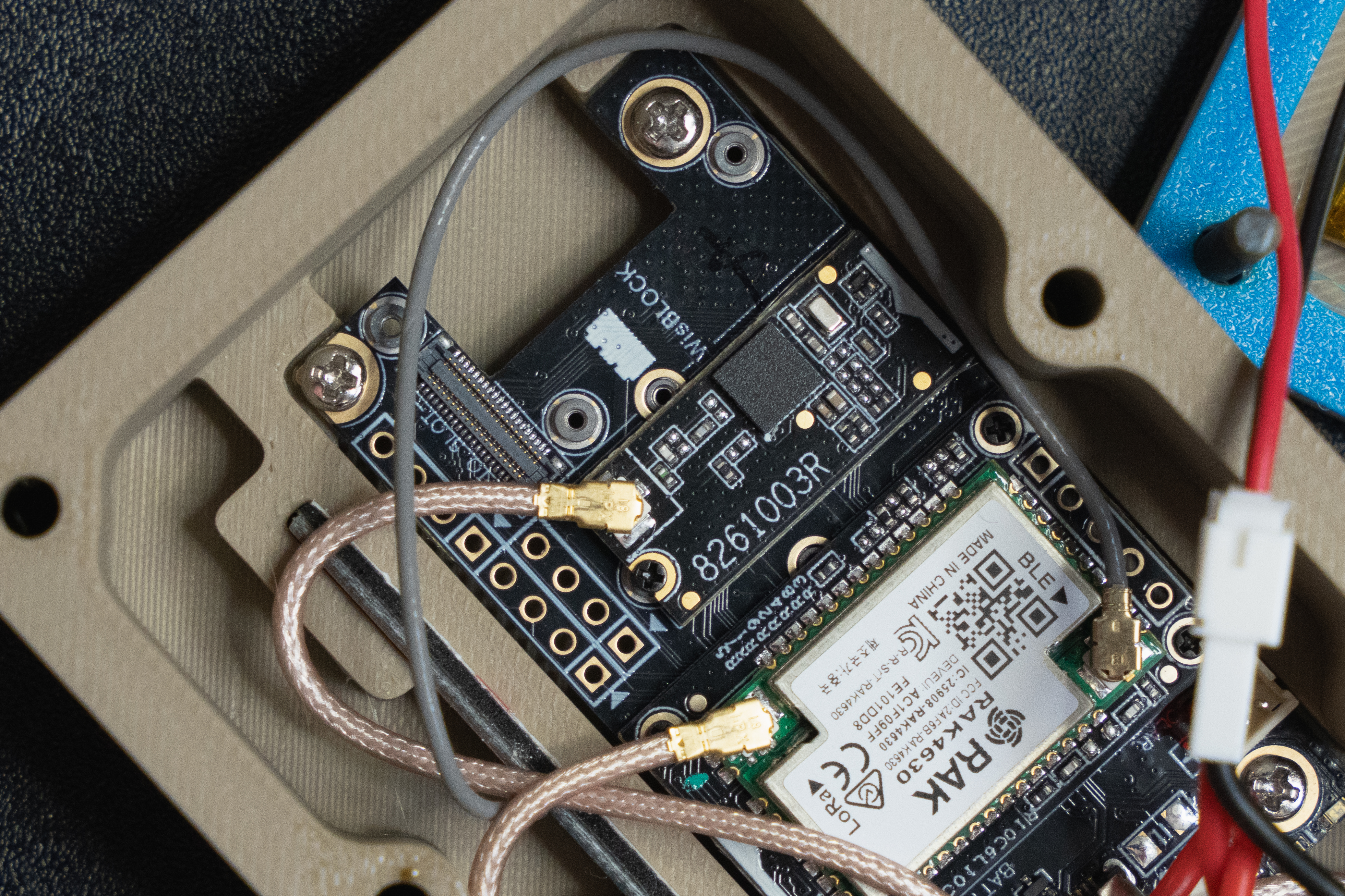
-
Insert the USB-C plug of the USB-C adapter into your RAK19007 board
- Note: Route the cable so that it tucks under the SMA pigtails and rotary switch

- Note: Route the cable so that it tucks under the SMA pigtails and rotary switch
-
Install the main board into the main enclosure body using the RAK included screws
-
Connect the pigtail cables to their respective IPEX connectors including the BLE antenna that came with your RAK device
-
Press fit the BLE antenna in the small slot next to the main board


-
Install six M3 brass inserts in the back of the enclosure main body
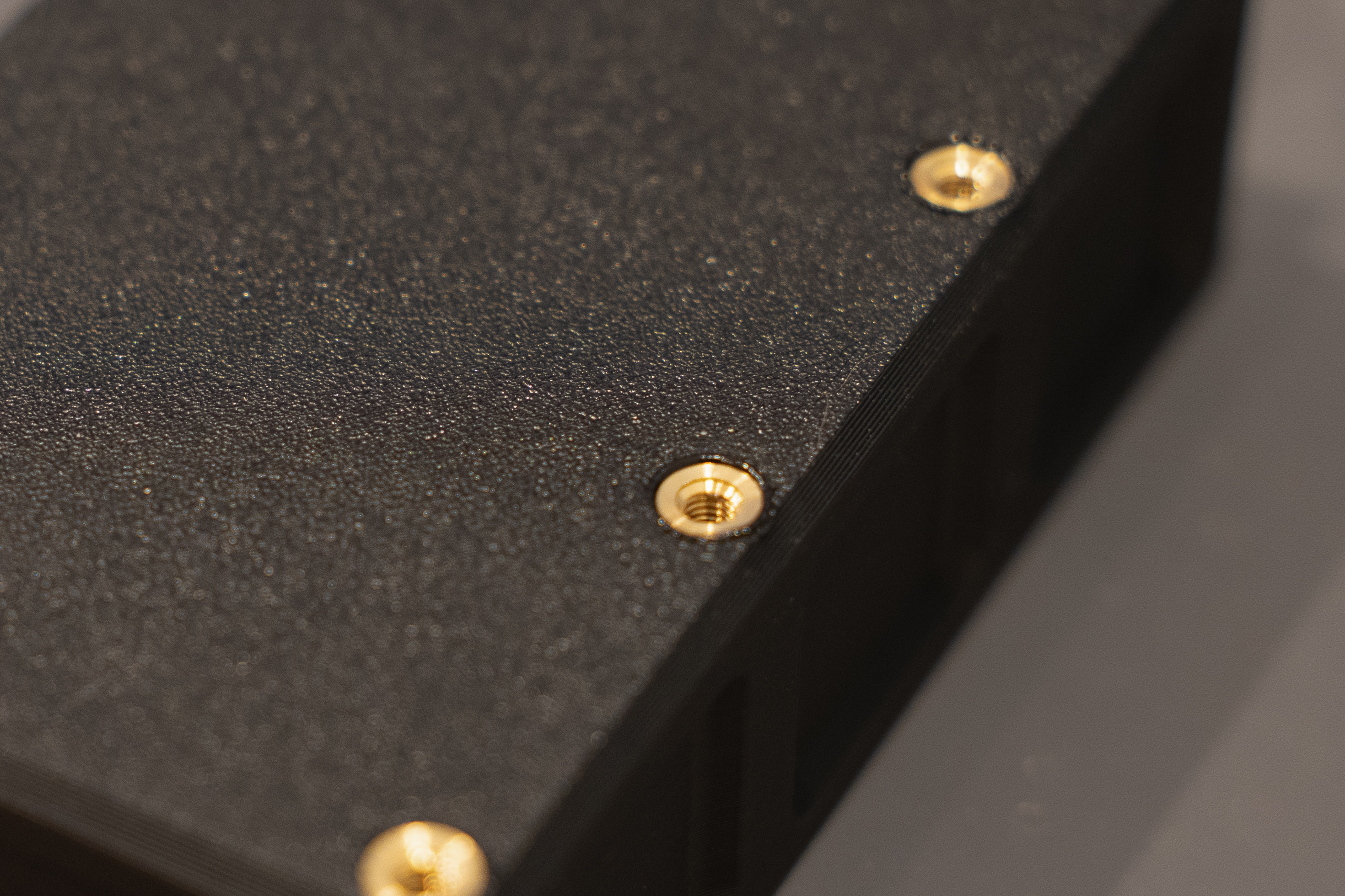
-
Install three light pipes in the
C,H, andUpositions on your enclosure lid
-
Using double-sided tape, attach your LiPo pack to the inside of the enclosure lid

-
Place the gasket and lid onto the enclosure main body so that the gasket is between the lid and main body

-
Using six M3x30mm screws, fasten the enclosure shut
-
Install the power switch knob onto the rotary switch


- The design is not intended to be waterproof. It is simply meant to be water and dust resistant
- To power the unit on, place the switch in the
Iposition - To power the unit off, place the switch in the
Oposition - Charge and program the device through the USB-C power mounted to the enclosure bulkhead
- When connected to USB-C power, the device will only charge the battery when the switch is in the
Iposition - When connected to USB-C power, the device will power on even if the switch is in the
Oposition - Connect a GPS antenna to the SMA connector labeled
G - Connect a LoRa antenna to the SMA connector labeled
L - Use the side grid panel for indentification markings
-
There are extra files located in the "STL" folder if you wish to print your own light pipes and USB passthrough.
-
Extra Purchase USB-C Breakout Boards
usbCap.mov
-
The case is modified to remove the lanyard opening, the antenna mounting flange thickness is reduced, the the USB passthrough opening was altered.

-
The lightpipe is printed in clear PETG. The "Arachne" wall generator was used in OrcaSlicer. Insert a pipe into each opening and fix with an adhesive.

-
The USB passthrough is four parts: USB-C holder, retention nut, cap, and lanyard. The lanyard was printed in TPU.

-
Press-fit the female USB breakout board into the holder. This is a very tight fit and may require adjustments to the print depending on your printer.
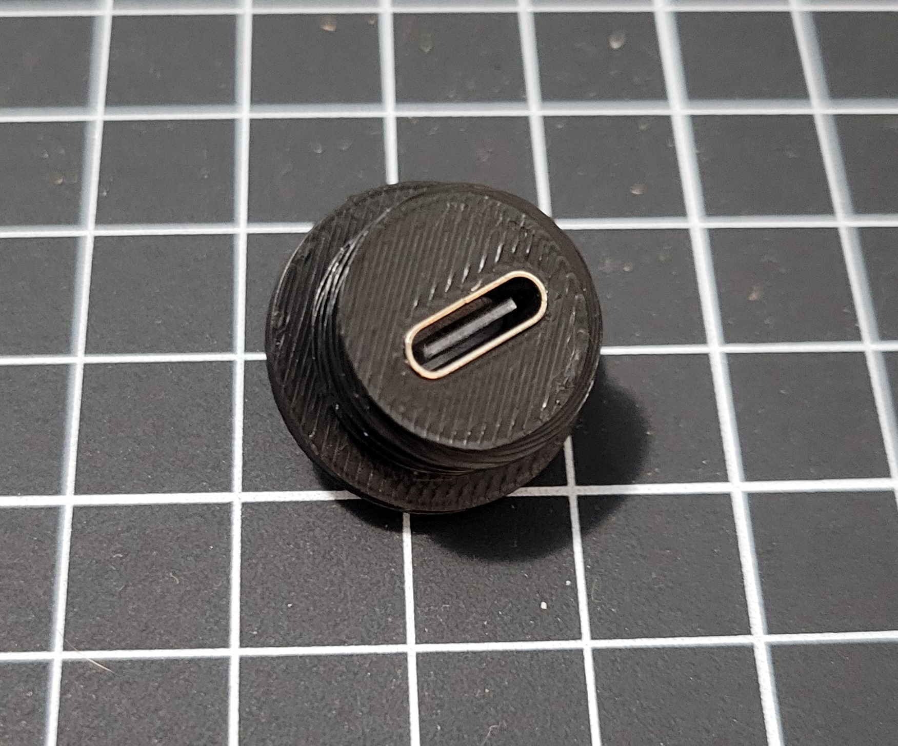
-
Cut roughly two inches of a four-conductor ribbon cable (four individual wires also work). Solder one end to the female USB breakout in the holder from the previous step. Solder the other to a male USB breakout. The connections are straight through without crossover. Use 3/8" or equivalent shrink tube to insulate the connections.

-
Install the male end of the cable into the RAK19007 board. You may have to loosen the board for it to fit. This will not fit into the original case, you must use the modified version linked above.

-
Verify functionality by connecting a USB power source.


